Note: Descriptions are shown in the official language in which they were submitted.
CA 02322040 2000-08-18
WO 99/42676 PCT/US99/03613
10 METHOD OF MAKING A
REINFORCEMENT PANEL SHEET
Field of the Invention
The present invention relates to reinforcement of wood structural members
such as beams, columns, and trusses and other members such as wood furniture,
utility poles, and wood composite members. More particularly, the present
invention relates to synthetic reinforcements having rough and unfinished
outer side
edges formed of low strength material.
Background of the Invention
Beams, trusses, joists, and columns are the typical structural members that
support the weight or toads of structures, including buildings and bridges.
Structural members may be manufactured from a variety of materials, including
steel, concrete, and wood, according to the structure design, environment, and
cost.
Wood furniture such as desks and bookshelves support weight such as computer
and
office equipment and heavy reference books.
Wood structural members are now typically manufactured from multiple
wood segments that are bonded together, such as in glue-laminated members,
laminated veneer lumber and I-beams. They can also be manufactured with wood
fibers in a polymer matrix such as parallel strand timber or orientated strand
board.
These manufactured wood structural members have replaced sawn lumber or
timbers because the former have higher design limits resulting from better
inspection and manufacturing controls. Wood is a desirable material for use in
CA 02322040 2000-08-18
WO 99/42676 PCT/US99/03613
2
many structural members because of its various characteristics, including
strength
for a given weight, appearance, cyclic load response, and fire resistance.
In any application, a load subjects a structural member to both compressive
and tensile stresses, which correspond to the respective compacting and
elongating
forces induced by the load on opposite sides of the member. By convention, a
neutral plane or axis extends between the portions of the member under
compression and tension. The structural member must be capable of bearing the
compressive and tensile stresses without excessive strain and particularly
without
ultimately failing.
Reinforcement of wood structural members in regions subjected to tensile
stresses are known. For example, U.S. Patent No. 5,026,593 of O'Brien
describes
the use of a thin flat aluminum strip to reinforce a laminated beam. The use
of a
synthetic tension reinforcement having multiple aramid fiber strands held
within a
resin matrix adhered to at least one of the wood segments in the tension
portion of
the structural member is described by the inventor of the present application
in
"Reinforced Glued-Laminated Wood Beams" presented at the 1988 International
Conference on Timber Engineering.
U.S. Patent Nos. 5,362,545 and 5,456,781 of Tingley describe methods of
adhering the reinforcement to wood using conventional non-epoxy adhesives.
Manufacture of the above-mentioned reinforced structural members results in
a significant amount of waste of the relatively expensive synthetic
reinforcement
material. This waste is generally the result of a planing process used to
reduce the
outside edges of the structural member to produce finished outer side edges.
Additionally, planing away the synthetic reinforcement fiber strands causes
significant wear on the cutting tools.
Therefore, a need exists for a method of producing structural wood members
with synthetic reinforcements without significant waste of the synthetic
reinforcement material. Furthermore, a need exists for a method of producing a
finished edge on a structural wood member without significant wear of the
cutting
tools.
CA 02322040 2000-08-18
WO 99/42676 PCT/US99/03613
3
Summary of the Invention
It is an object of this invention to provide a synthetic reinforcement panel
for
a laminated wood structural member having rough unfinished edges adapted to be
planed away during a finishing process.
It is another object of the invention to provide a synthetic reinforcement
panel having outer side edges formed of plural low strength fiber strands.
Still another object of the invention is to provide a synthetic reinforcement
panel having at least one longitudinal row of low strength fibers located
between the
outer side edges.
Yet another object of the invention is to provide a continuous panel sheet
having plural longitudinal rows of low strength fibers.
In a preferred embodiment, the present invention includes a synthetic
reinforcement for glue laminated wood structural members in which multiple
elongate wood segments and at least one synthetic fiber reinforcement are
bonded
together with their lengths generally aligned. However, the synthetic
reinforcement
can be used with all forms of wood and wood composites from solid wood to
plywood to parallel strand lumber. The synthetic fiber reinforcement includes
multiple synthetic fiber strands having a high modulus of elasticity in
tension and/or
compression held within a resin matrix. These fiber strands are relatively
high in
cost. The outer side edges of the reinforcement are formed from low strength
fibers
made of material such as hemp, cotton or polyester. The assembled wood member
has a width formed by the rough edges of the laminae. The synthetic fiber
reinforcement is formed with a width that is substantially matched to the
rough
width of the wood member. The rough edges are then machined to form a finished
width. Only the low strength fiber edges of the reinforcement are machined
away
avoiding waste of the high cost synthetic fiber strands. Additionally, the low
strength fiber edges cause less wear on the cutting tools. Therefore, the low
strength fiber edges substantially reduce cost, reduce machinery wear, and
improve
overall manufacturing ease.
In another preferred embodiment, the synthetic reinforcement includes a
longitudinal row of low strength fibers located between the outer side edges.
The
CA 02322040 2000-08-18
WO 99/42676 PCT/US99/03613
4
synthetic reinforcement can then be separated along the longitudinal row into
separate synthetic reinforcement panels each having outer side edges formed of
low
strength fibers.
In still another preferred embodiment, a synthetic reinforcement sheet is
formed with outer side edges of low strength fibers and plural longitudinal
rows of
low strength fibers located between the outer side edges. The reinforcement
sheet
can then be separated along the longitudinal rows to form plural synthetic
reinforcement panels each having outer side edges of low strength fibers.
Additional objects and advantages of this invention will be apparent from the
following detailed description of preferred embodiments thereof which proceeds
with reference to the accompanying drawings.
Brief Description of the Drawings
Figure 1 is an elevation view of an exemplary glue laminated structural
wood member having a synthetic fiber reinforcement according to the present
invention.
Figure 2 is a perspective view of a section of synthetic tension reinforcement
with portions cut away to show the alignment and orientation of the fibers.
Figure 3 is a perspective view of a section of synthetic compression
reinforcement with portions cut away to show the alignment and orientation of
the
fibers.
Figure 4 is a perspective view of a synthetic reinforcement with low strength
fiber edges and a central longitudinal row of low strength fibers.
Figure 5 is a view similar to Fig. 4 showing the synthetic reinforcement split
along the longitudinal row of low cost Bbers.
Figure 6 is a perspective view of a synthetic reinforcement sheet with plural
longitudinal rows of low strength fibers.
Figure 7 is a view similar to Fig. 6 showing the synthetic reinforcement
sheet split along one of the longitudinal rows of low strength fibers.
Figure 8 is a perspective view of a pultrusion apparatus for producing an
elongate synthetic reinforcement of the present invention.
CA 02322040 2000-08-18
WO 99/42676 PCT/US99103613
Figure 9 is an elevation view of a sheet forming apparatus for producing an
elongate synthetic reinforcement of the present invention.
Figure 10 is an elevation view of a pull forming apparatus for producing an
elongate synthetic reinforcement of the present invention.
5 Figure 11 is a front perspective view of a reinforcement panel in wood
furniture.
Figure 12 is a partial perspective view of a foam panel.
Figure 13 is an elevation view of a reinforcement panel used with a utility
pole.
Detailed Description of Preferred Embodiments
Figure 1 shows a glulam wood structural member 10 having multiple wood
laminae 12 that are bonded together and are preferably elongate boards. The
laminae may be solid wood, plywood, or wood composite. A number of structural
composite lumber products utilize phenol resorcinol and other types of
mechanical
and chemical adhesives to provide a rigid or semi-rigid bond between wood
fibers.
Most often, the purpose of the adhesive is to provide shear transfer between
the
wood fibers or layers of wood fibers. Under long term loading, the wood fibers
and the adhesive are subject to creep deformation. Any type of additive to the
adhesive to reduce the long term creep (or the short term mechanical shear
strength)
would be a significant contribution to the wood composites industry. For
example,
glued laminated timber beams (glulam) are produced in laminating plants by
gluing
together dry lumber, normally of 2 in. or 1 in. nominal thickness, under
controlled
conditions. Parallel strand lumber (PSL) is manufactured by laminating long
and
narrow strands of wood veneer with the axis of the wood fibers parallel to the
long
axis of the PSL member. The strands are completely covered with phenol
resorcinol or phenol formaldehyde and formed through a press under heat and
pressure to produce a continuous member, which can be cut at any length.
Laminated veneer lumber (LVL) is manufactured using wood veneers bonded
together with phenol resorcinol (or another mechanical adhesive) with the
grain in
each layer running parallel to the adjacent sheet. LVL is used for beams,
joists,
headers, and flanges. Particle and fiber boards are manufactured using small
wood
CA 02322040 2000-08-18
WO 99/42676 PCTNS99/03613
6
wafers (chips, sawdust, shavings, flakes, wafers, or strands) mixed with an
adhesive
(numerous types of adhesives used) and formed on a mat and pressed at the
required
pressure and temperature to cure the adhesive.
The resulting panel products are used in a wide variety of situations.
Oriented strand board is used for sheathing and diaphragm applications and
also as
the web member in wood I joists. Particleboard and chipboard are used in
mostly
non-structural applications, such as shelves and furniture, and are notorious
for
excessive creep deformations. Plywood consists of thin layers of wood bonded
with
the grain at right angles to each other between adjacent layers (usually). A
layer
may consist of one or more veneers. Peeling the log on a lathe produces the
veneers. The veneers are then pressed together (aligned as described above)
with
an appropriate type of adhesive under heat and pressure. Plywood is used for
sheathing and diaphragm applications and also as the web member in wood I
joists.
Other examples of where such panels are used include concrete form work
panels,
truck-trailor floors, cargo container floors, and scaffold planking.
Reinforcing
various types of panels discussed previously with high strength fibers placed
in
specific areas improves structural capacity, creep resistance, economic
viability and
long-term load resistance.
In this configuration, glue laminated wood member 10 is configured as a
glue-laminated timber according to manufacturing standards 117-93 of the
American
Institute of Timber Construction (AITC) of Englewood, CO.
A typical structural use of glue laminated wood member 10 is to extend as a
beam over and bear a load along an otherwise open region. As a simplified,
exemplary representation of such use, glue laminated wood member 10 is shown
with its ends supported by a pair of blocks 14 and bearing a point load 16
midway
between blocks 14. It will be appreciated, however, that glue laminated wood
member 10 of the present invention could also bear loads distributed in other
ways
(e.g., cantilevered) or be used as a truss, joist, or column.
Under the conditions represented in Figure 1, a lowermost lamina 20 is
subjected to a substantially pure tensile stress, and an uppermost lamina 22
is
subjected to a substantially pure cempr°ssive stress. To increase the
tensile
CA 02322040 2000-08-18
WO 99/42676 PCTNS99103613
7
toad-bearing capacity of glue laminated wood member 10, at least one layer of
synthetic tension reinforcement 24 is adhered between lowermost lamina 20 and
a
next adjacent lamina 26 or, alternatively, to only an outer surface 28 of
lowermost
lamina 20. To increase the compressive load-bearing capacity of glue laminated
wood member 10, at least one layer of synthetic compression reinforcement 30
is
adhered between uppermost lamina 22 and a next adjacent lamina 32 or,
alternatively, to only the outer surface 34 of uppermost lamina 22. Although
two of
each synthetic reinforcements 24 and 30 are shown, it is understood that any
number of synthetic reinforcements 24 and 30 may be used depending on the
application. Synthetic reinforcements 24 and 30 are described below in greater
detail.
Synthetic tension reinforcement 24 and synthetic compression reinforcement
30 are generally centered about load 16 and preferably extend along about two-
fifths
to three-fifths the length of wood structural member 10, depending on load 16.
It
can also extend the full length of the wood structural member 10. A pair of
wood
spacers 35 are positioned at opposite ends of synthetic tension reinforcement
24
between laminae 20 and 26 to maintain a uniform separation therebetween.
Similarly, a pair of wood spacers 35 are positioned at opposite ends of
synthetic
compression reinforcement 30 between laminae 22 and 32 to maintain a uniform
separation therebetween. The reinforcements 24 and 30 may be place externally
of
the wood structural member 10.
General aspects of the process for manufacturing of glue laminated structural
wood member 10 are the same as the process for manufacturing conventional glue
laminated structural wood members. With regard to the manufacture of
conventional glue laminated structural wood members, wood laminae are carried
by
a conveyor through a glue spreadei; which applies multiple thin streams of
adhesive
along the length of each wood lamina on one of its major surfaces.
Wood laminae are successively aligned with and set against other wood
laminae in a stack that may be oriented horizontally or vertically. The wood
laminae are arranged so that the adhesive on the major surface of one wood
lamina
engages the bare major surface of an adjacent wood lamina. After all the wood
CA 02322040 2000-08-18
WO 99/42676 PCTNS99/036I3
8
laminae are aligned with and set against each other, pressure in the range of
about
125-250 psi is applied to the stack and the adhesive allowed to cure. As is
known
in the art, sufficient pressure is applied to establish consistent gluelines
between
adjacent wood laminae 12 of no more than 4 mils (0.10 mm) thick. The edges of
S the adhered stack of wood laminae 12 are then planed to a finished width so
that
the sides of all wood laminae 12 are exposed to form a conventional glue
laminated
structural wood member. This function can be performed by sawing as well.
Epoxy is one type of adhesive suitable for use in the manufacturing process.
However, epoxy is expensive. Less expensive alternatives are nonepoxy
adhesives,
such as resorcinol. Other nonepoxy adhesives include phenol resorcinol,
formaldehyde resorcinol, melamine including cross-linked melamine, PVA
including
cross-linked PVA, isocyanate, polyurethane, and urea-based adhesives.
In a first preferred embodiment, synthetic fiber reinforcements 24 and 30 are
carried through a conventional glue spreader (not shown), which applies
multiple
thin streams of adhesive along the length of each reinforcement 24 or 30 on
one of
its major surfaces. Adhesion between wood laminae 12 and reinforcements 24 or
30 can be relatively poor when the adhesive is applied in the conventional
manner.
Adhesion is improved, however, when the adhesive is spread to generally
completely cover the major surfaces of synthetic fiber reinforcements 24 and
30.
It will be appreciated that such spreading of the adhesive can be
accomplished by spreading the adhesive applied to one of the major surfaces of
synthetic fiber reinforcements 24 and 30 or by spreading the adhesive applied
to one
of the major surfaces of a wood lamina to be applied to one of synthetic fiber
reinforcements 24 and 30. The spreading of adhesive may be accomplished, for
example, by manually spreading the adhesive before synthetic fiber
reinforcements
24 and 30 and adjacent wood laminae 12 are engaged or by engaging them and
sliding them against each other before the adhesive sets.
During manufacture of the wood member 10, different wood laminae 12 are
successively set against each other with synthetic fiber reinforcements 24 and
30
positioned as desired to form a stack. The stack may be oriented horizontally
or
vertically so that the sides of adjacent wood laminae and synthetic
reinforcements
CA 02322040 2000-08-18
WO 99/42676 PGT/US99/03613
9
are aligned. Since the laminae 12 and the reinforcements 24 and 30 have
substantially the same widths it is not necessary to secure reinforcements 24
and 30
to the stack with pin nails or banding as in previous reinforced wood members.
Thus, the time and expense of assembling the stack is reduced.
Preferably, synthetic fiber reinforcements 24 and 30 are manufactured with
respective rough widths 42 and 44 (Figs. 2 and 3) that are substantially
matched to
the rough width of wood member 10 (extending into the plane of Figure 1).
Thus,
the widths 42 and 44 of synthetic fiber reinforcements 24 and 30 have
substantially
the same original width as the wood laminae 12 used to form wood member 10.
The original widths of wood laminae 12 used to form wood member 10 can vary so
long as they are greater than the finished width of wood member 10. The
original
reinforcement width can be the average of these rough widths or whatever is
suitable for conditions.
Figure 2 is an enlarged perspective view of a preferred synthetic tension
reinforcement 24. The tension reinforcement 24 has a large number of synthetic
fibers 52 that are arranged substantially parallel to one another and parallel
to the
longitudinal axis of the reinforcement 24. The fibers 52 have a relatively
high
moduli of elasticity in tension and may be made of, for example, an aramid or
high
performance polyethylene, fiberglass, or carbon having a modulus of elasticity
in
tension in a range of about 10 x 106 psi (69,000 Mpa) to about 55 x 106 psi
(380,000 Mpa). These fibers 52 are generally high cost fibers and it is
desirable to
prevent waste of these fibers during machining of the wood member 10 to form
finished edges. Additionally, these high strength fibers cause substantial
wear on
machine tools when the edges are machined away.
In order to prevent machining away of the high cost, high strength fibers 52
the edges 54 of the tension reinforcement 24 are formed from low strength, low
cost cotton, hemp, and/or polyester fibers 56. For illustration purposes, the
fibers
56 are shown as having a slightly larger diameter than the fibers 52. However,
it is
to be understood that the diameters of fibers 56 and 52 may or may not be the
same. Only the outer longitudinal edges 54 are formed of the low strength
fibers 56.
These fibers 56 fill out the die or pack out the reinforcement profile during
the
CA 02322040 2000-08-18
WO 99/42676 PCT/US99/03613
pultrusion process to maintain packing fiber matrix volume ratios, alignment,
and
prevention of fiber crossover or rollover when the reinforcement is produced.
A resin material 58 surrounds and extends into the interstices between the
low strength fibers 56 and the high strength fibers 52 to maintain them in
their
5 arrangement and alignment. The fiber/resin volume ratio of the reinforcement
24 is
within a range of about 60 percent fibers/40 percent resin to about 83 percent
fibers/ 17 to 40 percent resin. The reinforcement 24 has a composite modulus
of
elasticity in tension in a range of about 6 x 10⁶ psi (41,000 Mpa) to about 35
x 106
psi (240,000 Mpa). To facilitate adhesion to the wood laminae 12, the
10 reinforcement 24 is preferably manufactured and treated as described in
U.S. Patent
No. 5,362,545 so that material from the fibers closest to a major surface of
the
reinforcement protrude from the resin. This may be done by abrading the
surface
with an abrasive in a direction transverse to the longitudinal direction of
the
reinforcement. Alternatively, the surface may be subject to a chemical
treatment
prior to curing the resin causing voids in the surface which remove portions
of the
resin and expases the fibers. Other methods of surface treatment may include
the
use of broken rovings which protrude from the resin after curing, the use of
an
epoxy-type of adhesive to achieve sufficient bond strength, or the use of
cellulose
on the surface.
The original or rough edges of the wood member 10 are then machined
to produce a finished edge using a high speed cutting tool. The majority of
material
planed away is from the low strength fiber edges of the reinforcements 24 and
30.
The amount of material removed from each edge of the wood member 10 during
machining is generally in the range of about .125 inches to about .5 inches.
Therefore, each edge 54 preferably has a width 60 within this range. As a
result,
machining away of the high strength synthetic fibers 52 is avoided.
Additionally,
the modulus of elasticity of the low strength fibers 56 is generally less than
500,000
psi (3450 Mpa). The fibers 56 are readily machinable with conventional cutting
tools, such as, for example, high speed steel planer knives. Forming the edges
54
with the low strength fibers 56 helps prevent waste of the high strength
fibers 52,
reduces machinery wear, and increases manufacturing effectiveness.
CA 02322040 2000-08-18
WO 99/42676 PCT/US99/03613
11
Figure 3 is an enlarged perspective view of a preferred synthetic
compression reinforcement 30. The compression reinforcement 30 has a large
number of synthetic fibers 62 that are arranged substantially parallel to one
another
and to the longitudinal axis of the reinforcement 30. These fibers may be
commercially available such as carbon and fiberglass fibers, which have a
modulus
of elasticity in compression in the range of about 10 x 106 to 55 x 106 psi
(69,000 -
380,000 MPa). The reinforcement 30 is manufactured substantially the same as
reinforcement 24 but may include a combination of additional fibers 64 of
aramid or
high performance polyethylene. The fibers 62 and 64 may be layered or co-
mingled. The edges 66 of reinforcement 30 are formed of low strength fibers 67
similar to fibers 56 in reinforcement 24. Resin 68 extends between the
interstices
of the fibers 62, 64 and 67 to maintain alignment of the fibers. The edges 66
have
a width 70 in the range of about .125 inches to about .5 inches. Synthetic
compression reinforcement 30 has a fiber/resin volume ratio within a range of
about
60 percent fibers/40 percent resin to about 83 percent fibers/ 17 percent
resin. The
reinforcement 30 has a modulus of elasticity in compression in the range of
about
18 x 106 to 19 x 106 psi (124,000 - 131,000 MPa).
The resin material 58 and 68 used in fabrication of both reinforcement 24
and reinforcement 30 is preferably an epoxy resin, but could alternatively be
other
resins such as polyester, vinyl ester, phenolic resins, polymides, or
polystyrylpyridine (PSP) or thermoplastic resins such as polyethylene
terephthalate
(PET) and nylon-66.
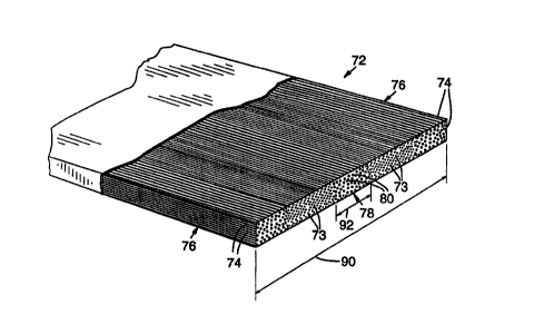
Figure 4 shows an alternative synthetic reinforcement 72 similar to the
synthetic reinforcement 24 in Fig. 2 in that the synthetic reinforcement 72
has
synthetic fibers 73 and longitudinal rows of low strength fibers 74 forming
outer
side edges 76. However, the synthetic reinforcement 72 has a longitudinal row
78
of low strength fibers 80 located between the low strength fiber outer side
edges 76.
The synthetic reinforcement 72 can then be split along the longitudinal row 78
as
shown in Fig. 5. This produces two separate synthetic reinforcements 82 and 84
each having low strength fiber edges 86 and 88, respectively. Thus, it can be
seen
that the low strength fibers 80 form one side edge of each synthetic
reinforcement
CA 02322040 2000-08-18
WO 99/42676 PC'T/US99/03613
12
82 and 84. Specific dimensions, such as the overall width 90 of the synthetic
reinforcement 72 may vary depending on the width desired for each resulting
synthetic reinforcement 82 and 84. Additionally, the spacing of the
longitudinal
row 78 of low strength fibers 80 from the side edges 76 may also vary to
produce
synthetic reinforcements having different widths. The width 92 of each
longitudinal
row 78 of low strength fibers 80 may also vary depending on conditions and
each
application.
Figures 6 and 7 show another method of forming a synthetic reinforcement.
In this method, a unitary sheet 94 is formed as seen in Fig. 6 having
synthetic
fibers 96 and longitudinal rows 97 of low strength fibers 98 spaced at various
locations along the sheet 94. Individual synthetic reinforcement panels 100
can then
be formed from the sheet 94 by splitting it along the longitudinal rows 97 of
low
strength fibers 98 as seen in Fig. 7. The resulting individual synthetic
reinforcement panels 100 have outer side edges 106 formed from low strength
fibers
98. As shown in Fig. 6, the longitudinal rows 97 are evenly spaced from the
outer
side edges 106 of the sheet 94. However, it is understood that the
longitudinal rows
97 may be variously spaced to produce individual synthetic reinforcement
panels of
differing widths. Additionally, the widths 110 of the longitudinal rows 97 may
vary.
Synthetic fiber reinforcements 24 and 30 and the synthetic fiber sheet 94
may be fabricated by various methods, such as a sheet forming or pull-forming
process. Preferably, the reinforcements 24, 30, and 94 are fabricated by
pultrusion,
which is a continuous manufacturing process for producing lengths of fiber
reinforced plastic parts. Generally, pultrusion involves pulling flexible
reinforcing
fibers through a liquid resin bath and then through a heated die where the
reinforced
plastic is shaped and the resin is cured. Pultruded parts typically have
longitudinally aligned fibers for axial strength and obliquely aligned fibers
for
transverse strength. In accordance with the present invention, however,
preferred
reinforcements 24, 30, and 94 are manufactured with substantially all
respective
fibers in a parallel arrangement and longitudinal alignment to provide maximal
strength. In some circumstances, such as to enhance shear resistance in
CA 02322040 2000-08-18
WO 99/42676 PCT/US99/03613
13
reinforcements 24, 30, and 94 less than substantially all of respective fibers
52, 62,
and 94 would be in a parallel arrangement and longitudinal alignment.
Figure 8 shows a preferred pultrusion apparatus 120 for fabricating synthetic
fiber reinforcements 24, 30, and 94. Multiple bobbins 122 carry synthetic
fiber
S rovings 124. As is known in the art, filaments are grouped together into
strands or
fibers, which may be grouped together into twisted strands to form yarn, or
untwisted strands to form rovings. Rovings 124 are fed through openings 126 in
an
alignment card 128 that aligns that rovings 124 and prevents them from
entangling.
Openings 126 are typically gasketed with a low friction material, such as a
ceramic
or plastic, to minimize abrasion of or resistance to rovings 124.
In the fabrication of the reinforcements 24, 30, and 94 it is understood that
the bobbins 122 containing different fibers are constructed and arranged so
that as
the various fibers exit the card 128 they are arranged to form the
reinforcement
profiles as shown in Figs. 2-6.
Rovings 124 pass from card 128 to a first comb 130 that gathers them and
arranges them parallel to one another. Rovings 124 then pass over a tensioning
mandrel 132 and under a second alignment comb 134. They pass through
close-fitting eyelets 136 directly into a resin bath 138 where they are
thoroughly
wetted with resin material. Passing rovings 124 into resin bath 138 through
eyelets
136 minimizes the waste of rovings 124 whenever the pultrusion apparatus 120
is
stopped. Resin-wetted rovings 124 are gathered by a forming die 140 and passed
through a heated die 142 that cures the resin material and shapes the rovings
124
into reinforcements 24, 30, and 94. Multiple drive rollers 144 pull the
reinforcements 24, 30, and 94 and rovings 124 through pultrusion apparatus 120
at
a preferred rate of 3-S feet/minute (0.9-1.5 m/minute).
To minimize waste and simplify handling and use, the reinforcements 24,
30, and 94 are formed so as to be wound onto a reel (not shown) so that
arbitrary
lengths can be drawn and cut for use. Alternatively, the reinforcements 24,
30, 94
may be formed into pre-cut sheets. The reinforcements 24, 30, and 94 are
formed
with relatively small thicknesses of about 0.25 cm to about 6.4 cm (0.010 in. -
CA 02322040 2000-08-18
WO 99/42676 PCT/US99/03613
14
0.0250 in.) and can be wound onto reels having a diameter in the range of
about 99
cm to about 183 cm (39 in. - 72 in.).
Pultrusion apparatus 120 is capable of forming synthetic reinforcements 24,
30, and 94 without longitudinal cracks or faults extending through and with
cross-sectional void ratios of no more than 5 percent. Cross-sectional void
ratios
refer to the percentage of a cross-sectional area of synthetic reinforcements
24, 30,
and 94 between respective fibers 52, 62, and 96 typically occupied by resin
material, and is measured by scanning electron microscopy. The absence of
faults
and the low void ratios assure that synthetic reinforcements 24, 30, and 94
are of
maximal strength and integrity.
The preferred resin materials, as described above and applied to rovings
124, have a glass transition temperature within a range of 250-300°F.
Glass
transition is an indicator of resin flexibility and is characterized as the
temperature
at which the resin loses its hardness or brittleness, becomes more flexible,
and takes
on rubbery or leathery properties. A glass transition temperature within the
preferred range is desirable because it provides a minimal fire resistance
temperature. The preferred cure rate of the resin material, which is the
amount of
material that cures from a monomer structure to a polymer structure, is 78 to
82
percent. It has been determined that synthetic reinforcements 24, 30, and 94
with
cure rates within this range have higher shear stress bearing capabilities at
interfaces
with both synthetic reinforcements and wood laminae.
Preferably, a fiber tension force in the range of about three to eight pounds
is applied to rovings 124 during the resin cure. The fiber tension force may
be
applied as a back pressure by tensioning mandrel 132 in combination with combs
130 and 134 or by the use of friction bobbins 122, wherein rotational friction
of the
bobbins may be adjusted to provide the desired back pressure on rovings 124.
Such
tension in the fibers assists in maintaining their parallel arrangement and
alignment
in reinforcements 24, 30, and 94. Also, by curing the resin material while the
fibers
are under tension, reinforcements 24, 30, and 94 have greater rigidity and
therefore
decrease deflection of wood member 10 upon loading.
CA 02322040 2000-08-18
WO 99/42676 PCT/US99/03613
Figure 9 shows a preferred sheet forming apparatus 150 for fabricating
synthetic fiber reinforcements 24, 30, and 94. In this process, a fabric
material is
stitched using any type of fiber having the required weight and denier aligned
in
different directions that may be required in the end use of the panel. The
fiber is
5 then processed between a layer of cellulose or aramid fibers on each side of
the
fiber for other adhesion methods described earlier. The width of the resulting
panel
may range from 30 - 50 inches and has a fiber volume of between 40 - 50
percent.
The panel material is then rolled into coils of typically about 2,000 - 5,000
lineal
feet depending on the thickness or is pre-cut into sheets. The lower layer of
10 cellulose or aramid fibers 152 is fed from a lower roller 154 and lower
auxiliary
roller 156. The fabric sheet 158 is fed from an upper roller 160 and upper
auxiliary roller 162. The fabric sheet 158 and lower layer 150 are run through
a
resin spray 164 over a heated table 166 maintained at a certain temperature.
The
fabric/fiber composite then runs past a wet-out roller 168 to thoroughly wet
the
15 composite. The composite then passes thhrough squeeze rollers 174 and 172
to
remove excess resin and maintain uniform thickness. The upper layer of
cellulose
or aramid fibers 174 is fed from a roller 176 over squeeze roller 170 and onto
the
composite. The final composite is then run through an oven 178 for final
curing.
Figure 10 shows a preferred pull forming apparatus 180 for fabricating
synthetic fiber reinforcements 24, 30, and 94. The pull manufacturing process
is a
combination of the pultrusion process and the sheet forming process. Fibers
182
are pulled from friction bobbins 184 and run through alignment guard 186. From
the alignment guard 186 the fibers are through a comb 188. The fibers are then
run
through back tensioning rollers 190 and 192 and passes over plural roller 194,
196,
198, and 200 as the fibers are passed through a resin bath 202. A lower layer
of
cellulose or aramid fibers 204 are fed from a roller 206 over roller 208 to
combine
with the fibers which run over a heated conveyor table 210 with a top platen
used to
pull the fibers to ensure tensioning. A wet-out roller 2I2 ensures complete
wetting
of the fibers. The fibers are then run through squeeze rollers 214 and 216 to
remove excess resin. At this point an upper layer of cellulose and/or aramid
fibers
218 is fed from an upper roller 220 and added to the fibers sheet. The fiber
sheet
CA 02322040 2000-08-18
WO 99/42676 PCT/US99/03613
16
is then run through ovens 222 for final curing. The resulting sheet may have a
width ranging from between 20 - 50 inches or greater and have a fiber volume
in
the range of 50 - 60 percent.
The thickness of the sheet formed from the sheet forming or pull forming
processes are generally less than about 2 mm in thickness. The panel may be
used
in multiple layers with different fibers running in different directions in
different
layers. The weight of fiber, type of fiber, and the direction of the fibers in
each
layer are designed depending upon the end use of the panel. As seen in Fig.
11, the
panel 224 may not extend the entire length or width of the wood structural
member
and may only be used on surface areas having high stress concentration such as
in
wood furniture 226 shown in Fig 11. This reduces the overall cost of the
reinforcement. One use for such a panel includes reinforcement of foam panels.
The panel can either reinforce the structure member on an outer surface or
within
the structural member depending upon end use.
Another type of reinforcement panel use includes reinforcement foam 228
(Fig. 12). Foam panels 228 are reinforced with composite panels 230 and 232 on
each side of the foam panel 228 for use as structural roof panels, floor and
shear
panels of the walls. Alternatively, the foam panel 228 can be reinforced with
chopped high strength fiber like fiberglass and carbon to increase the
compressive
strength of the foam for use in high tensile strength areas without the
composite
panels on each side.
Continuous fibers processed into a discontinuous fiber mat and held together
with the help of a binder can be used to increase the strength of the member
as a
reinforcement without using the fibers in a polymer matrix before adhering
them to
the structural member. This can be done by first applying it directly in the
glueline
or to the surface of the structural member by passing the need for a plastic
matrix.
Wide width panels 233 may also be used to reinforce wood utility poles 234
below ground {Fig. 13). Wood utility poles 234 are subject to decay at areas
in and
around the ground level. In order to repair such damage the poles 234 may be
reinforced with wide width reinforcements 233 to restore strength of the
poles.
Multiple layers of wide width panels 233 with fibers aligned in different
directions
CA 02322040 2000-08-18
WO 99/42676 PCTNS99/03613
17
are wrapped around the pole 234 and secured with epoxy adhesives. Carbon
fibers
or other high compressive strength fibers can be used in the transverse
direction of
the reinforcement to restrain the high tangential stresses induced in the
reinforcement. The stress is induced due to the radial expansion of the pole
234 by
change in moisture content of the utility pole or environmental loads on the
pole,
e.g. wind. Polyurethane or other types of foams can be used as filler in the
gap at
the interface between the utility pole and the reinforcement. The panel 233
can be
made by the sheet forming process using the carbon or other high compressive
strength fibers in the transverse direction on one side of the panel through
the
thickness. The shrinkage in the matrix as it cures/polymerizes is resisted
more by
the carbon fibers than the other fibers in the transverse direction. This
leads to a
curving of the panel widthwise. The curving widthwise allows it to conform
more
effectively as a reinforcement to round objects, such as utility poles,
concrete
columns, piles and pipes.
Used as a reinforcement at a connector, such as a bolt, the reinforcement
restrains the wood member from shearing at the bolted joint. The reinforcement
panel increases the bolt bearing capacity of the member.
It will be obvious to those having skill in the art that many changes may be
made to the details of the above-described embodiment of this invention
without
departing from the underlying principles thereof. The scope of the present
invention
should be determined, therefore, only by the following claims.