Note: Descriptions are shown in the official language in which they were submitted.
CA 02322046 2000-08-16
WO 00/39819 PCT/US99/24040
A STRIP WOUND INDUCTION COIL WITH IMPROVED HEAT TRANSFER AND
SHORT CIRCUIT WITHSTANDAB1LITY
DESCRIPTION
Technical Field
Applicant's invention relates generally to a low voltage strip wound coil for
use in
a transformer, and more particularly, to a method for improving the short
circuit
withstandability and heat transferability ratings of the coil.
Background Art
A transformer generally consists of a laminated, ferromagnetic core, high
voltage
windings, and low voltage windings. The windings of dry type transformers with
primary
voltages over 600 volts have generally been constructed using one of three
types of
techniques: conventional dry, resin encapsulated, or solid cast. The
conventional dry
method uses some form of vacuum impregnation with a solventless type varnish
on a
completed assembly consisting of the core and the coils or individual primary
and
secondary coils. Some simpler methods required just dipping the. core and the
coils in
varnish without the benefit of a vacuum. The resulting voids or bubbles in the
varnish
2o that are inherently a result of this type of process due to moisture and
air, does not lend
itself to applications above 600 volts. The resin encapsulated method
encapsulates a
winding with a resin with or without a vacuum but does not use a mold to
contain the
resin during the curing process. This method does not insure complete
impregnation of
the windings with the resin and therefore the turn to turn insulation and
layer insulation
must provide the isolation for the voltage rating without consideration of the
dielectric
rating of the resin. The solid cast method utilizes a mold around the coil,
which is the
principal difference between it and the resin encapsulated method. The
windings are
placed in the mold and impregnated and/or encapsulated with a resin under a
vacuum,
which is then allowed to cure before the mold is removed. Since all of the
resin or other
process material is retained during the curing process, there is a greater
likelihood that
the windings will be free of voids, unlike the resin encapsulated method
whereby air can
reenter the windings as the resin drains away before and during curing.
Cooling
channels can be formed as part of the mold. One: type of such a transformer is
SUBSTTTUTE SHEET (RULE 26)
CA 02322046 2000-08-16
WO 00/39819 PCT/US99/24040
-2-
manufactured by Square D Company under the trademark of Power-Cast
transformers.
Another example of a cast resin transformer is disclosed in U.S. Patent
4,488,134.
Since the resin used in coating solid cast coils results in a greater solid
bond
between adjacent conductors than is possible with resin encapsulated coils,
solid cast
coils exhibit better short circuit strength of the windings. Because the
conductors in the
coils are braced throughout by virtue of the solid encapsulant, there is less
likelihood of
movement of the coils during short circuit conditions and short circuit forces
are
generally contained internally. An added benefit is that by having greater
mass, there is
a longer thermal time constant with the solid cast type coils and there is
better protection
1o against short term overloads.
External bracing, foil-wound coils, or selective geometry in the shape of the
coils
must be used in the resin-encapsulated method to prevent movement of the coifs
caused by the forces of short circuit faults. Insulating material wound with
the sheet
conductors may have an adhesive coated on it to prevent movement of adjacent
windings during the resin impregnation process which will allow the various
windings to
retain a circular shape and to provide a better bond between windings since
the various
windings are held in place while processing. The resin encapsulated coils
generally
have lower radial comprehensive strength, poor radial strength, and higher
assembly
costs. Resin injected into the coils will have a tendency to leak from the
coils during the
curing cycle, resulting in some voids in the coil.
The resin encapsulated method does however have several distinct advantages
over solid cast coils. They are simpler to manufacture than cast resin coils
and require
less resin and other materials, resulting in less weight and lower costs.
Additionally, the
cast resin process requires an epoxy resin, which also requires fillers such
as glass
fibers to provide mechanical strength. The epoxy resins generally are limited
to a 185
deg. C temperature, whereas resin encapsulated coils can utilize polyester
resins that
can achieve 220 deg. C ratings. Given these advantages, it would be desirable
to
produce coil windings for use in transformers and other inductive devices,
with the resin
encapsulated method if there were a method to increase the strength of the
coil
windings to prevent movement during short circuits.
The air gap between the high and low voltage coils is dependent on having the
same geometry between the outer surface of the inner coil and the inner
surface of the
outer coil. For non-molded coils, there is generally a distinct bulge at the
point where
SUBSTTTUTE SHEET (RULE 26)
CA 02322046 2000-08-16
WO 00/39819 PCT/US99/24040
-3-
terminations or leads are attached. As a result, the air gap between coils
will be uneven.
Inductive reactance of a transformer is determined by this air gap, along with
the number
of turns in the coil and the physical dimensions of the coil. Controlling
these factors will
result in limiting short circuit currents and thus controlling voltage
withstand ratings.
Summary Of The Invention
Accordingly, the principal object of the present invention is to provide a low
voltage winding constructed according to the resin encapsulated method which
overcomes the above mentioned disadvantages.
Another objective of the invention is to provide a transformer winding
constructed
according to the resin encapsulated method that will prevent drainage of the
resin that
will be applied during the resin encapsulation stage.
A further objective of the invention is to provide a method for manufacturing
a
transformer winding constructed according to the resin encapsulated method
which
prevents moisture penetration into the windings and which will prevent
flashovers due to
moisture condensation.
Yet a further objective of the invention is to provide a transformer winding
constructed according to the resin encapsulated method utilizing aluminum
strip wound
windings which will prevent conductor movement during short circuit fault
conditions.
2o In one embodiment of the invention, a low voltage coil is formed on a
special
cylinder or mandrel with a flat surface on a portion of the cylinder from
which one
external lead which is welded to a conductor sheet, such as aluminum or
copper, will
rest during the start of the winding. The flat surface will allow the windings
to retain a
circular shape. Along with the sheet aluminum, a layer of insulating material
will be
including during the winding process. The insulating material may have an
adhesive
coated on it that will prevent movement of adjacent windings during the resin
impregnation process, which will allow the various windings to retain a
circular shape. In
the present invention, the resin will be able to provide a better bond between
windings
since the various windings are held in place while processing. This bonding
will provide
3o extra strength to the windings and prevent movement of them under short
circuit
conditions. To provide the necessary voltage creep strength ratings, the
insulation
windings will extend beyond the top and bottom edges of the conductor sheet
windings.
SUBSTITUTE SHEET (RULE 26}
CA 02322046 2000-08-16
WO 00/39819 PCT/US99/24040
The space created between the insulating sheets is filled with a dielectric
material to
control movement of the conductor sheets during short circuit conditions.
At a predetermined number of turns, spacers will be added to form air channels
within the windings during the winding process until the desired number of
turns has
been reached. The inner and outer insulating layers between the channels
thusly
created extend further beyond the sheet conductors and are reinforced to
provide
stiffness to prevent collapse of the edges over the cooling channels. This
forms a pocket
that is filled with a suitable material to prevent moisture and other
contaminants from
entering and contaminating the coils. The end of the winding will terminate at
another flat
surface and the other external lead will be attached to maintain the circular
shape.
Lastly, the pockets formed on the bottom portions of the coil by the inner and
outer insulating layers are sealed with a suitable sealant. Further, all
vertical seams in
the inner and outer insulating layers are also sealed. This will prevent
drainage of the
resin that will be applied during the next stage. After the coil is thusly
assembled, it will
be subjected to a vacuum-pressure impregnation (VPI) process. The coil is then
placed
in a vacuum chamber that will be evacuated, which will remove the air, and in
particular,
voids between adjacent windings will be essentially eliminated. A liquid resin
is then
introduced into the chamber, still under a vacuum, until the coil is
completely
submerged. After a suitable time interval, which will allow the resin to
impregnate the
insulation, the vacuum is released and pressure is applied to the free surface
of the
resin. This will force the resin to impregnate the remaining insulation voids.
The coil is
then removed from the chamber or the resin from the chamber is drained. The
coil is
allowed to drip dry and then is placed in an oven to cure the resin to a
solid. A further
buildup of resin could be accomplished by repeating the process with resins
having a
higher viscosity to provide the finished coil with a conformal coating for a
better
appearance and greater isolation from environmental factors.
The completed coil will have superior basic impulse level (BIL) protection
since
the amount of voids is minimized, short circuit withstand ability is improved
since there is
little chance of the individual windings moving due to the bonding, and
overload capacity
is increased since heat generated in the windings will transfer to the cooling
ducts better
through a solid mass than if voids were present in the windings.
Other features and advantages of the invention will be apparent from the
following specification taken in conjunction with the accompanying drawings in
which
SUBSTITUTE SKEET (RULE 26)
CA 02322046 2000-08-16
WO 00/39819 PCT/US99/24040
-5-
there is shown a preferred embodiment of the invention. Reference is made to
the
claims for interpreting the full scope of the invention that is not
necessarily represented
by such embodiment.
Brief Description of Drawings
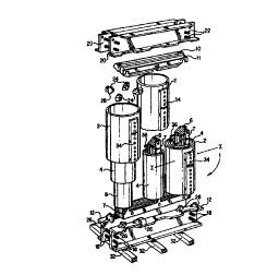
FIG. 1 is an exploded isometric view of a three phase dry-type transformer
using
a low voltage coil constructed according to the present invention.
FIG. 2 is a partial cross sectional view of a cure surrounded by the low
voltage
coil constructed according to the present invention, which in turn, is
surrounded by a
cast resin high voltage coil of the type depicted in the transformer of Fig.
1.
FIG. 3 is a detailed cross sectional view along line 1-1 of Fig. 1 detailing
the low
voltage coil of Fig. 2.
FIG. 4 is an enlarged view of area II detailing the upper portion of the low
voltage
coil depicted in Fig. 2.
FIG. 5 is an enlarged view of area III detailing the lower portion the low
voltage
coil of Fig. 2.
FIG. 6 is an enlarged view of area II detailing the upper portion of the low
voltage
coil depicted in Fig. 2, and illustrating an alternative method of reinforcing
the edges of
the insulating material.
Detailed Description
Although this invention is susceptible to embodiments of many different forms,
a
preferred embodiment will be described and illustrated in detail herein. The
present
disclosure exemplifies the principles of the invention and is not to be
considered a limit
to the broader aspects of the invention to the particular embodiment as
described.
FIG. 1 illustrates a typical three phase transformer 1 using a low voltage
coil 4
constructed according to the preferred embodiment. Although a three phase
transformer
is shown, it is to be understood that the invention is not to be limited to
three phase
construction. A high voltage coil 2 surrounds the low voltage coil 4. The high
voltage coil
2 is constructed using a cast resin process, the details of which are well
known and are
therefore not an object of this invention. U.S. Patent No. 4,523,171 discloses
one such
method. The low voltage coil 4 is constructed using a VPI resin encapsulated
process,
which will be discussed later. A core 6 is formed in the shape of a cruciform
from
SUBSTTTUTE SHEET (RULE 26)
CA 02322046 2000-08-16
WO 00/39819 PCTNS99/24040
-6-
laminated straps of iron for ease of manufacturing. A core locking strap 7 is
added to the
top of the stack. After the core legs 6 are stacked, various methods, which
are not an
object of the present invention, are used to keep the core legs compressed.
After the
core legs are thusly secured, an epoxy type paint is applied to exposed areas
for
environmental protection. An upper core yolk 10 is secured to the core 6 by
mating strap
11 with core locking strap 7 after the low voltage coils 4 and high voltage
coils 2 have
been inserted over the three legs of the core 6. Lower core clamp 12 holds and
secures
core 6 through with mounting hardware 18. Upper core clamp 20 holds and
secures
upper core yolk 8 similarly with mounting hardware 22. Upper 24 and lower 26
mounting
blocks support high voltage coil 2 and low voltage coil 4. Tab 28 of mounting
blocks 24,
26 maintains an air gap 30 between the coils 2, 4. Mounting feet 32 can be
attached for
stability. Terminal blocks 34 allow for high voltage connections and have
provisions for
selected various voltage taps for a wide selection of input and output
voltages.
Terminals 36 provide the means for low voltage connections. A transformer thus
assembled can accommodate input voltages up to 36 kV, with a power rating
between
112.5 - 10,000 kVA.
Referring to FIG. 2, a partial cross sectional view of the low voltage coil 4
is
illustrated, constructed according to the present invention, which in tum is
surrounded by
a cast resin high voltage coil of the type depicted in the transformer of Fig.
1. An air gap
40 separates the core leg 6 from the low voltage coil 4. The low voltage coil
4 is
composed of multiple windings 42, 44, 46 of flexible sheet conductors such as
copper or
aluminum, with formed air channels 43, 45 to provide a means of cooling during
operation of the transformer 1. Air gap 30 separates the low voltage coil 4
from the high
voltage coil 2 with the distance of the gap being determined by the tab 28 on
mounting
blocks 24, 26 previously mentioned. High voltage coil 2 consists of wire
conductors 48,
49, with molded air channels 50. The distance 52 between the top of the
conducting
materials in coil 2 and the top yolk 10 is chosen to meet high voltage to
frame
clearances. Likewise, the distance 53 between the top of the conducting
materials in coil
4 and the top yolk 10 is chosen to meet the low voltage to frame clearances.
Air gap 54
provides isolation between voltage phases.
The cross sectional view of Fig. 3, taken along line I-I of Fig. 1, provides a
more
detailed illustration of the preferred embodiment of the low voltage coil 4 of
the present
invention. The outer or high voltage coil 2 is separated from the low voltage
coil 4 by the
SUBSTITUTE SHEET (RULE 26)
CA 02322046 2000-08-16
WO 00/39819 PCT/US99/24040
_7_
air gap 30. The essentially circular shape of the low voltage coil 4 allows
the air gap 30
to remain constant throughout its entirety which will reduce susceptibility to
voltage
impulses and will help control impedance changes during short circuit
conditions.
Air gap 40 separates the cruciform core leg 6 from the low voltage coil 4. The
low
voltage coil 4 is composed of multiple windings 42, 44, 46 of flexible sheet
conductors
such as copper or aluminum, with formed air channels 43, 45 to provide a means
of
cooling during operation of the transformer 1.
Dogbone spacers 76, 78 are staggered and strategically placed and sized so as
to ensure that the final exterior shape at the air gap 30 is circular. The
spacers 76, 78
are pultruded glass reinforced polyester. Spacing between adjacent spacers 76,
78
varies from 1.5 inches to 2.5 inches on center. This spacing is critical since
air flow in
the created air ducts 43, 45 will be restricted if they are too close
together, resulting in
poorer cooling characteristics. If the spacing is too far, voids could be
created between
the insulating layers 60 and the sheet conductors 62 that make up the windings
42, 44,
and 46. This could result in localized hot spots and decrease the mechanical
rigidity of
the over coil 4, which could reduce the short circuit withstandability.
Leads 36, 36' are insulated with a creep and strip barrier composed of Nomex
or
other suitable flexible sheet insulation. This insulation is to prevent
voltage breakdown
between the low voltage winding 4 and the core 6 or other grounded surfaces.
The
combination of the flat surfaces 80, 82, and duct stick 84 allow the leads 36,
36' to be
contained inside the low voltage coil 4 with no apparent bulge. In addition
the leads 36,
36' are bonded to the body of the low voltage coil 4. A glass rope or other
suitable
material, running parallel to the lead from top to bottom along its major axis
is sufficiently
porous to absorb resin during the VPI process to provide lead support and
reinforcement, preventing movement of the lead from short circuit forces.
A more detailed view of Area II of Fig. 2 is shown in Fig. 4 to illustrate a
means
for reinforcing the top and bottom edges of the windings 42, 44, and 46 of the
low
voltage coil 4. The low voltage coil 4 is composed of multiple laminations of
flexible
sheet conductors. The description for winding 44 will also hold true for the
other two
windings 42 and 46. Film insulation sheets such as Nomex form an excellent
winding
layer insulation system. This layer 60 is extended beyond the edge of the
sheet
conductors 62, as designated by the distance X for obtaining the necessary
creep
strength requirements.
SUBSTTTUTE SHEET (RULE 26)
CA 02322046 2000-08-16
WO 00/39819 PCT/US99/24040
_$_
The coif is wound from flexible sheet conducting material start at a flat
surface
80. Multiple laminations of flex sheet conductor lead are used to form the
external leads
36, 36' that are welded to the sheet conductor 62. The leads 36, 36' are
deformed during
assembly to allow the high voltage coil 2 to be inserted around the coil
during final
assembly of the transformer 1 and reshaped appropriately after assembly for
external
connections.
In some types of coils, the insulating layers 60 are coated with a B-staged
thermoset adhesive. Use of the thermoset adhesive allows the layers to become
bonded
during a preheating process before the VIP process. Using a diamond or similar
pattern
will create sufficient bonding between the sheet conductors 62 to retain the
shape of the
coil during the VPI process and still provide sufficient unbonded areas for
the resin to
impregnate the body of the coil during the VPI process. The type of resin is
chosen to
provide a suitable temperature index for the intended temperature rise of the
coils. In
addition it must be able to fill the voids and improve the thermal conduction
between the
sheet conductors 62 and the heat dissipating surfaces, and lastly, prevent
contaminants
such as water, oils, acids, and industrial fumes from entering and
contaminating the
coils.
Previous low voltage coils constructed using the resin encapsulated method did
not insure complete impregnation of the windings with the resin and therefore
the turn to
turn insulation and layer insulation must provide the isolation for the
voltage rating
without full consideration of the dielectric rating of the resin. This method
resulted in low
radial compressive strength, poor radial heat transfer, and high assembly
costs. The
combination of poor radial strength and heat transfer is due in part to
drainage of the
resin applied after the coil is wound. The extra cost is due to requiring
extra bracing of
the coil required due to low radial compressive strength. Whereas the use of
the
insulating layers being coated with the B-staged-thermoset adhesive greatly
increases
the interlayer bonding, the B-stage resin can only do this where it is in
intimate contact
with the conductor sheets. Often the various layers of conductor and-
insulating sheets
become distorted and assume different curvatures as they cross the various
spacers 76,
78 of Fig. 3, used in forming the air channels 43, 45. This creates gaps
between the
adjacent layers that are to be filled with the insulating resins during the
VPI process.
Further, there are vertical seams 86, 88, 90 shown in Fig. 3, formed between
by the
various layers of conductor sheets 64 and insulating sheets created when
forming the
SUBSTITUTE SHEET (RULE 26)
CA 02322046 2000-08-16
WO 00/39819 PCTNS99/24040
-9-
air channels 43, 45 and the inside and outside conductor layers 63, 65. These
seams
can result in leakage of the resin during and after the resin encapsulation
process. This
resin can also drain out from the bottom of the coil when it is removed from
the VPI
process and allowed to cure, resulting in a permanent loss and the creation of
possible
voids within the low voltage coil 4 itself.
To prevent this leakage of resin, before the completed coil assembly is
subjected
to the resin encapsulation process, the bottom cavity 92 is sealed with a
suitable sealant
94 as shown in Fig. 5, which is a more detailed view of Area II of Fig. 2.
Likewise, the
vertical seams 86, 88, 90 shown in Fig. 3 are also sealed with the same
sealant. The
sealant chosen is an epoxy having a quick , 3-5 minute cure time. This epoxy
should be
formulated to be highly thixotropic so that it does not flow into the gap 66
created below
the conductor sheet winding 62 and the between the insulating sheets 60. The
use of
this sealant will prevent the leakage of the resin during and after the resin
encapsulation
process. Since the injected resin does not seep from the coil during the VPI
process and
during the curing period, the resultant coil will have greater short circuit
withstandability
and improved radial heat conduction due to bonding throughout the body of the
coil
without the need for using an adhesive coating on the insulating winding and
without the
need for preheating the coil before the start of the VPI process to allow the
adhesive to
set. This greatly reduces the time and cost required to manufacture the coil.
When winding the insulating layers 60 with the sheet conductors 62, the edges
of
the layers 60 can collapse due to the soft texture of the material, which
could result in
blockage of the cooling ducts, limiting the cooling characteristics of the
coil. Outside
barriers 64 which extend a distance Y beyond the edge of the insulating layers
60,
provide the stiffness to prevent this collapse and are selected based on the
voltage
class of the transformer. For a minimum of a basic impulse level (BIL) of 1kV,
common
for an isolation rating between the core 6 and the low voltage coil 4, the
inside barrier 63
will be one thickness of .031 inch sheet insulation such as a product
trademarked
Glastic plus two pieces of another insulator, 5 mil thick, such as a product
trademarked
Nomex. For a minimum BIL of 95kV, common for an isolation rating between the
high
voltage coil 2 and the low voltage coil 4, the outside barrier 65 will be two
thicknesses of
.031 inch sheet insulation. The space between the insulating layers 60 is
packed with a
glass mat or felt edge material 66 to control the movement of the sheet
conductors 62
during short circuit conditions. The glass felt edge material 66 could be any
type of
SUBSTITUTE SHEET (RULE 26)
CA 02322046 2000-08-16
WO 00/39819 PCT/US99/24040
-10-
porous dielectric characterized by high temperature rating and stability. The
dielectric
constant must be greater than air to maintain proper voltage spacing
requirements.
Examples of such a material 66 are Nomex 411, Cequin or other types of glass
fibrous material. This material 66 functions to provide protection to the
sheet conductors
62 against water entry or other contaminants and to provide electrical
insulation
properties for withstanding high voltage transients, in addition to
providing., the
mechanical rigidity of the ends of the coil for mechanical clamping and short
circuit
withstand forces. The material 66 must allow the sheet conductors to be
impregnated
with a suitable electrical insulating resin during the VIPI process.
Supporting the outside layers next to the air channels 43, 45 of the multiple
windings 42, 44, 46 with the outside barriers 64 results in increasing the
overall radial
dimensions of the windings and therefore the overall dimensions of the
completed
transformer 1. This extra thickness translates into extra material
requirements for the
core and coil material, including the conductors, insulating film, and resin
used to
encapsulate the windings. An alternative solution is to provide a reinforcing
material
along the edges of the outer insulating layers 60 next to the air channels 43,
45, for the
distance Y, that will provide the stiffness to prevent this collapse of the
edges.
Thus, Fig. 6 illustrates the use of Cequin strips 70 or reinforcing nylon
strands 72
which will maintain the circular shape of the completed coil during the VIPI
processing
and prevent the collapse over the air channels 43, 45. The end result will be
a finished
coil that will have a smaller diameter than one manufactured using the
traditional Glastic
material, using less material and therefore having lower cost.
After VIPI processing, the completed coil is then baked in an oven at 350
degrees F. for two hours. An air dry resin is then applied in the void 68 to
contour the
ends of the windings, eliminating voids, and facilitating moisture run-off.
Instead of using
the dry resin, other coil finishing treatments and extensions can be employed
in the
voids 68 and 92. A moisture cured silicone RTV, an epoxy resin having suitable
cure
characteristics for the application, or a filled polyester resin could be
substituted for the
air dry resin. Another option requires a woven or braided fibrous rope being
placed in
the void 68 before the coil is subjected to the VPI process. The rope could be
made of
glass fiber, Nomex, or other heat resistant material.
While the specific embodiments have been illustrated and described, numerous
modifications are possible without departing from the scope or spirit of the
invention.
SUBSTTTUTE SHEET (RULE 26)