Note: Descriptions are shown in the official language in which they were submitted.
CA 02322078 2000-10-03
1
ABSORBENT ARTICLE AND PROC88S 1~OR MANUFACTURING THE SAME
BACKGROUND OF THE INVENTION
1. Field of the Invention:
The present invention relates to an absorbent article
such as sanitary napkin, panty liner and pad for incontinence
and, more particularly, it relates to an absorbent article
equipped with a surface sheet having good soft feeling,
cushioning property and shape retaining property, and to a
process for manufacturing the same.
2. Description of the Related Art:
Absorbent articles having a liquid-permeable surface
sheet at the liquid-receiving side of an absorbent layer are
disclosed, for example, in International Unexamined Patent
Publication (Kohyou) No. Heisei 10-502000.
Specifically, International Unexamined Patent
Publication (Kohyou) No. Heisei 10-502000 discloses a sanitary
napkin, in which a cover layer of a corrugated configuration
( or wavy shape ) is provided on a support layer so that the leakage
of the body fluid can be prevented by the wavy shape and the
flexibility of the wavy shape can make it comfortable to wear.
However, in the sanitary napkin mentioned above, the wavy
shape is apt to be deformed and flattened or fall down sideways
by the pressure of the user's body when the cover layer having
the wavy shape touches the skin. In addition, even when the
CA 02322078 2005-07-13 . ..
2
body pressure applied to the wavy shape fluctuates and is
lowered upon use, the cover layer hardly restores to the
original wavy shape from the flat or fallen state. As a
result the cover layer does not at all times closely touch the
skin of the user in an optimum state, and there are problems
that the excreted liquid spreads more than necessary on the
absorbent article resulting in sideways leakage and that soft
feeling to the skin and cushioning property are lowered.
SUMMARY OF THE INVENTION
The present invention has as one feature to provide an
absorbent article which, in preferred embodiments, can closely
contact with the user's skin at all times and which can retain
soft feeling and cushioning property, and also to provide a
process for manufacturing the same.
According to the invention, there is provided an
absorbent article comprising an absorbent layer and a liquid-
permeable surface sheet placed on a liquid-receiving side of
the absorbent layer for introducing excreted liquid from the
human body to the absorbent layer, wherein the surface sheet
is of a corrugated configuration to have valleys and peaks
extending in a longitudinal direction of the article and
alternately arranged in a transverse direction perpendicular
to the longitudinal direction, and wherein each valley has a
connecting part raised to connect
between two adjacent peaks.
CA 02322078 2000-10-03
3
In the absorbent article of the present invention, there
is provided the connecting part to connect between the peaks
of the surface sheet, so that the peaks are prevented from being
flattened or falling down sideways readily by the pressure of
user's body. Even if they are flattened or fall down sideways,
in addition, the connecting part can act elastically on the peaks,
when the body pressure is lowered, so that the peaks can readily
restore to the original shape. That is, even when the body
pressure fluctuates due to the movement of the user, the peaks
can respond to the movement of the user's body to be flattened
or restore to the original shape, whereby the close contact to
the user's skin can be always maintained in a high level.
Accordingly, the excreted liquid hardly spreads on the surface
sheet to thereby prevent sideways leakage effectively. In
addition, soft and cushiony feeling to the user is not lowered.
For example, the connecting part may connect side slopes
of the two peaks. With the connecting part being formed to
connect the side slopes of the peaks, the connected side slopes
can be readily raised up, when the body pressure having been
applied to the peaks is lowered, so that the peaks can readily
restore to the original shape.
Preferably, each valley has a plurality of connecting
parts arranged at regular intervals in the longitudinal
direction. In this case, it is preferred that the interval of
the connecting parts in the longitudinal direction is from 5
CA 02322078 2000-10-03
4
mm to 30 mm.
With the connecting parts in each valley being arranged
at regular intervals in the longitudinal direction, as
describer above, restoring ability of the corrugated
configuration is improved all over the surface sheet.
Preferably, the connecting parts are staggered in the
longitudinal direction, between two adjacent valleys.
With the connecting parts being arranged in such a
staggered manner, the connecting parts can easily restore the
individual peaks. In addition, the spread of the excreted
liquid in the transverse direction is easily prevented.
Preferably, the length in the transverse direction of the
top of the connecting part is from 1 mm to 10 mm.
Preferably, the height size (h) from the bottom of the
valley to the top of the connecting part falls within a range
of 20% to 80% the height size (H) from the bottom of the valley
to the top of the peak. Below the lower limit of the
aforementioned range, a restoring function of the corrugated
configuration by the connecting part is lowered. Above the
upper limit of the aforementioned range, on the other hand, the
connecting part is apt to touch the skin whereby the feeling
upon wear becomes bad.
Preferably, the surface sheet has a lower fiber density
in the connecting part than in the valley exclusive of the
connecting part. With the connecting part being made in such
CA 02322078 2000-10-03
a low density as above, the excreted liquid, which tends to flow
along the valleys and spread, is stopped by the connecting part.
Preferably, the surface sheet has a higher fiber density
in the bottom of the valley than in the top of the peak. Also
preferably, the surface sheet has a higher fiber density in the
top of the peak than in the side of the peak. Also preferably,
the surface sheet has a higher fiber density in the top of the
peak than in the connecting part and in the side of the peak,
and the fiber density in the connecting part is equal to or higher
than that in the side of the peak. Most preferably, the relation
of the fiber densities in respective parts of the surface sheet
is ( bottom of valley ) > ( top of peak ) > ( connecting part ) Z ( s ide
of peak).
As a result of the above, the feeling to the skin and the
cushioning property of the surface sheet can be improved.
Moreover, the excreted liquid is difficult to spread in the
longitudinal and widthwise directions of the valleys, so that
leakage from the edges of the article in the longitudinal and
transverse directions thereof can be suppressed. Accordingly,
the excreted liquid is quickly absorbed by the absorbent layer
through the surface sheet whereby little residual liquid
remains on the surface sheet and a fresh and dry feeling can
be achieved at all times.
Preferably, the back of the surface sheet is fixed to the
absorbent layer at the bottom of the valley. In this case,
CA 02322078 2000-10-03
6
displacement between the surface sheet and the absorbent layer
hardly occurs.
Preferably, the surface sheet is a laminate of a plurality
of nonwoven fabrics containing hydrophobic fibers. If it is
formed by laminating a plurality of bulky nonwoven fabrics, e. g. ,
air-through nonwoven fabrics, the surface sheet will have
improved soft feeling and cushioning property.
According to the invention, there is also provided a
process for manufacturing an absorbent article, comprising the
steps of:
(a) pressing a nonwoven fabric, which is supplied in a
predetermined direction, between a first shaping means and a
second shaping means to form a surface sheet, and
(b) placing and fixing the surface sheet on a liquid-
receiving side of an absorbent layer, wherein
the first shaping means has ribs and grooves extending
in the supplying direction of nonwoven fabric and alternately
arranged in a transverse direction perpendicular to the
supplying direction;
the second shaping means has ribs and grooves extending
in the supplying direction and alternately arranged in the
transverse direction, each rib of which has a plurality of
recesses formed at intervals in the supplying direction; and
the surface sheet formed in the step ( a ) has peaks each
compressed between the rib of the first shaping means and the
CA 02322078 2000-10-03
, 7
groove of the second shaping means, valleys each compressed
between the groove of the first shaping means and the rib of
the second shaping means, and connecting parts raised from the
valleys to connect between two adjacent peaks at the part
corresponding to the recesses of the second shaping means.
BRIEF DESCRIPTION OF THE DRAWINGS
Fig. 1 is a plan view showing an absorbent article
according to one embodiment of the invention, from a
liquid-receiving side thereof;
Fig. 2A is a partial cross sectional view taken along the
line IIA-IIA of Fig. 1, and Fig. 2B is a partial cross sectional
view taken along the line IIB-IIB of Fig. 1;
Fig. 3A is a partial cross sectional view taken along the
line IIIA-IIIA of Fig. 1, and Fig. 3B is a partial cross sectional
view taken along the line IIIB-IIIB of Fig. 1;
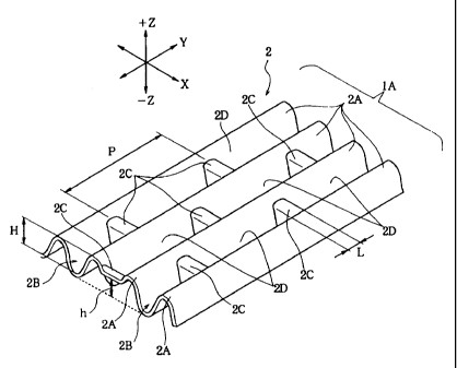
Fig. 4 is a partial perspective view of a surface sheet;
Fig. 5 is a perspective view of a multi-row mold for
shaping the surface sheet to have a corrugated configuration;
Fig. 6 is a perspective view of a convex mold for shaping
the surface sheet to have a corrugated configuration; and
Fig. 7 is a schematic view of another method for shaping
a surface sheet.
DESCRIPTION OF THE PREFERED EMBODIMENTS
CA 02322078 2000-10-03
As hereunder, the present invention will be illustrated
by referring to the drawings.
Fig. 1 is a plan view showing a sanitary napkin 1, as one
embodiment of the absorbent article of the invention, from a
liquid-receiving side thereof; Figs. 2A and 2B show cross
sections of Fig. 1 in the X direction, where Fig. 2A is a partial
cross sectional view taken along the line IIA-IIA while Fig.
2B is a partial cross sectional view taken along the line
IIB-IIB; Figs . 3A and 3B show cross sections of Fig. 1 in the
Y direction, where Fig. 3A is a partial cross sectional view
taken along the line IIIA-IIIA while Fig. 3B is a partial cross
sectional view taken along the line IIIB-IIIB; and Fig. 4 is
a partial perspective view only of a surface sheet (the
skin-contact surface) of the sanitary napkin.
As shown in Figs. 2A and 2B, the sanitary napkin 1 is
constructed to include mainly three components: a liquid-
permeable surface sheet (surface structure) 2; an absorbent
core ( absorbent layer ) 3 which absorbs excreted liquid such as
menstrual blood and urine; and a liquid-impermeable back sheet
4. In use, the surface sheet 2 makes contact with the user's
skin directly to receive the body fluid such as menstrual blood
excreted from the human body. The body fluid thus received is
passed through the surface sheet 2 and introduced into the
absorbent core 3 located therebelow.
The surface sheet 2 is composed of, for example, bulky
CA 02322078 2000-10-03
9
and highly-porous air-through nonwoven fabric, point-bond
nonwoven fabric, spun-bond nonwoven fabric, spun-lace nonwoven
fabric or melt-blown nonwoven fabric. In view of the
characteristics, an air-through nonwoven fabric which is bulky
and has an excellent cushioning property is most preferred.
For constituent fibers to form the above nonwoven fabrics,
use can be made mainly of hydrophobic synthetic fibers. The
synthetic fibers can be exemplified by those of PE
(polyethylene), PP (polypropylene), PET (polyethylene
terephthalate), etc.; core-sheath or side-by-side type fibers
of PE/PP, PE/PET, etc.; and so on. The nonwoven fabrics may
contain hydrophilic fibers such as regenerated cellulose fiber
(e. g., rayon fibers) in addition to the synthetic fibers.
The fibers per se may be finished to be soft by increasing
the elongation percentage by means of lowering the draft ratio
upon spinning the fibers. In this case, the fibers are
preferably finished to have an elongation percentage (maximum
tensile strain) in a dry state of 120% or less, so that a web
strength during carding of the fibers can be maintained. If
the elongation percentage exceeds 120%, the web strength
becomes insufficient and it is difficult to prepare a sheet.
More preferably, the elongation percentage is within a range
of 60% to 100%. Within this range, the web strength can be
maintained to an appropriate degree, while the fibers being made
sufficiently smooth.
CA 02322078 2000-10-03
The fineness of the fibers is preferably from 1 to 6
deniers. If the fineness is less than 1 denier, the liquid is
apt to remain on the surface sheet as residual liquid due to
a capillary action. If, on the other hand, the fineness is more
than 6 deniers, the surface sheet may have a hard and coarse
feeling.
In view of easy shaping of the sheet and prevention of
the residual liquid, the basis weight (This may be referred to
as "Metsuke" ) of the surface sheet 2 is preferably within a range
of 20 g/m2 to 120 g/m2.
The surface sheet 2 may be a single nonwoven fabric to
have a single layered structure. Alternatively, the surface
sheet 2 may be a compounded sheet which is prepared by laminating
two or more nonwoven fabrics, as shown in Figs. 2A to 3H. It
is optimum that the basis weight of the surface sheet 2 having
the single layered structure is 85 g/mz.
When the surface sheet 2 is a three-layered compounded
sheet, for example, the uppermost one of the three layers may
be a nonwoven fabric prepared by sheeting PE/PET fibers of a
core-sheath type ( fineness of 2 .5 deniers, fiber length of 51
mm) according to an air-through method to have a basis weight
of 30 g/m2, a CD strength of 190 g/inch and a thickness of about
0.5 mm. In this case, the core-sheath type fibers of the
uppermost (first) layer to contact the user's skin in use is
preferably of a filled-up (or dense) structure to have less
CA 02322078 2000-10-03
11
tension thereby to improve the feeling to the touch. On the
other hand, the intermediate and lowermost ( second and third )
layers are preferably formed of core-sheath type fibers of a
hollow structure to be highly bulky and to have an improved soft
feeling. Moreover, the skin-contact side (front surface) of
the first layer is preferably added with more titanium oxide
to reduce the so-called elasticity of the fibers thereby to
improve the feeling to the tough. More specifically, in the
second layer, the third layer, and the back surface (non-
skin-contact side) of the first layer, the content of titanium
oxide in the core component of the core-sheath structure is 0 . 5% .
On the other hand, in the skin-contact side of the first layer,
the content of titanium oxide is 4%.
As shown in Fig. 1, at the center of the surface sheet
2 of the sanitary napkin 1, there is formed a skin-contact part
1A of a nearly violin-shape. As shown in Figs. 2A and 2B, along
the periphery of the absorbent core 3 placed on the back sheet
4, the absorbent core 3 and surface sheet 2 are pressed together
to form a pressed part 3a. At this pressed part 3a, moreover,
the absorbent core 3 and surface sheet 2 are fixed to each other
by means of adhesion using a hot melt adhesive, thermal fusion,
or the like. The skin-contact part 1A is confined within the
pressed part 3a.
As shown in Figs. 1, 2A, 2B, 3A, 3B and 4, the skin-contact
part 1A is of a corrugated configuration (or wavy shape) to have
CA 02322078 2000-10-03
12
peaks 2A and valleys 2B extending in the longitudinal direction
( Y direction ) of the sanitary napkin 1 and alternately arranged
in the transverse direction ( X direction ) of the sanitary napkin
1. As shown in Fig. 3B and Fig. 4, in each valley 2B, there
is formed a connecting part 2C rising in a convex manner ( i. e. ,
rising from the bottom of the valley 2B in the +Z direction) .
The connecting part 2C extends in the transverse direction ( X
direction) to connect side slopes of two peaks 2A and 2A, which
are located at the sides of the valley 2B. Each valley 2B has
a plurality of connecting parts 2C.
In each valley 2B, these connecting parts 2C are arranged
at regular intervals P in the longitudinal direction to thereby
form a long groove 2D between two connecting parts 2C. The
length in the transverse direction of the top of the connecting
part 2C is preferably within a range of 1 mm to 10 mm, more
preferably, within a range of 2 mm to 6 mm. If it is less than
1 mm, the connecting part 2C hardly contributes to the
restoration of the corrugated configuration. If, on the other
hand, it is more than 10 mm, the corrugated configuration does
not provide sufficient soft feeling and therefore, it becomes
so rigid as to cause hard creases disadvantageously.
The interval P ( nearly the length of the long groove 2D )
is preferably within a range of 5 mm to 30 mm, more preferably,
within a range of 5 mm to 20 mm. If the interval P is more than
30 mm, the shape restoring property of the corrugated
CA 02322078 2000-10-03
13
configuration having the peaks 2A and the valleys 2B will be
lowered. If, on the other hand, the interval P is less than
mm, rigid feeling will increase to cause hard creases, and
soft feeling by the corrugated configuration will be impaired.
As shown in Fig . 4 , the height ( h ) from the bottom of the
valley 2B to the top of the connecting part 2C preferably falls
within a range of 20% to 80% the height (H) from the bottom of
the valley 2B to the top of the peak 2A. Here, the heights ( H )
and ( h ) are measured in the Z direction . I f the height ( h ) is
less than the lower limit of the aforementioned range, the
connecting part 2C hardly contributes to the restoration of the
corrugated configuration. If, on the other hand, the height
( h ) is more than the upper limit of the aforementioned range,
the connecting part 2C is liable to contact with the user's skin
thereby to provide uncomfortable feeling to the user.
In the course of the formation of the corrugated
configuration, the surface sheet 2 is pressed more forcibly in
the long groove 2D (the part exclusive of the connecting part
2C, of the valley 2B) than in the connecting part 2C. Therefore,
in the surface sheet 2, the long groove 2D has a higher fiber
density than that of the connecting part 2C. With the fiber
density of the connecting part 2C being made so lower, the
connecting part 2C can be made elastic . Accordingly, when the
peaks 2A are crushed, they can be readily restored to the
original shape by the recovery of the connecting part 2C.
CA 02322078 2000-10-03
14
When the excreted liquid is given to the surface sheet
2, the liquid is apt to spread along the long groove 2D ( i. e. ,
between two peaks 2A and 2A) , but is stopped by the connecting
part 2C having a low fiber density. Thus, the excreted liquid
is prevented from spreading more than necessary on the surface
sheet 2 . The liquid confined within the long groove 2D is passed
into the absorbent core 3 through the surface sheet 2. As a
result, the sanitary napkin 1 can absorb the excreted liquid
reliably while preventing sideways leakage.
Further, when the fiber density of the surface sheet 2
is made in such a manner that ( bottom of valley 2B ) > ( top of
peak 2A) > (connecting part 2C) a (side slope of peak 2A), the
following effects can be expected.
Firstly, when the fiber density at the top of the peak
2A is made lower than that of the bottom of the valley 2B, feeling
to the touch can be improved.
Secondly, when the fiber density of the side slopes of
the peaks 2A and 2A located at the sides of the valley 2B is
made lower than that of the top of the peak 2A, cushioning
property can be improved and feeling to the touch can also be
improved.
Thirdly, although the excreted liquid given to the bottom
of the valley 2B is apt to spread quickly in the longitudinal
direction of the surface sheet 2, the excreted liquid on the
bottom of the valley 2B is prevented from spreading by the
CA 02322078 2000-10-03
connecting part 2C and the side slopes, since the fiber densities
of the connecting part 2C and the side slopes are relatively
lower than that of the bottom of the valley 2B. This results
in the suppression of spread of the liquid all over the surface
sheet 2 in the longitudinal and transverse directions, whereby
leakage of the excreted liquid can be prevented.
Fourthly, the rate of absorption of liquid is higher in
the part having a higher fiber density than in the part having
a lower fiber density. Accordingly, the excreted liquid flown
into the long groove 2D can be quickly introduced into the
absorbent core 3 through the bottom of the valley 2B. Therefore,
the excreted liquid is difficult to spread in the longitudinal
and the transverse directions of the valley whereby the leakage
from the edges of the napkin in the transverse and the
longitudinal directions can be suppressed. In addition, the
excreted liquid can be quickly absorbed into the absorbent core
3 through the surface sheet 2, so that no residual liquid is
present on the surface sheet 2 to thereby provide a fresh and
dry feeling at all times.
In the sanitary napkin 1 using the surface sheet 2, the
two adjacent peaks 2A are connected by the connecting part 2C
formed in the valley 2B therebetween, so that the elongation
of the surface sheet 2 in the transverse direction ( X direction )
can be suppressed. Accordingly, the deformation of the peak
2A such as gushing in flat or falling sideways due to the
CA 02322078 2000-10-03
16
application of the pressure of the user's body to the skin-
contact part 1A can be made difficult to occur.
Even if a large pressure is applied from the user's body
to the skin-contact part 1A and the peaks 2A are crushed
resulting in deformation of the corrugated configuration, on
the other hand, the peaks 2A can rise up by the elasticity of
the connecting part 2C when the body pressure is decreased due
to the movement of the user's body. In addition, even if the
surface sheet 2 becomes flat in such a manner that the peak 2A
and the peak 2A expand in the transverse direction ( X direction ) ,
those peaks 2A and 2A are drawn due to a tensile elasticity in
the transverse direction of the connecting part 2C whereby the
surface sheet 2 can be easily restored to the corrugated
configuration from the flat state.
Therefore, the peaks and valleys of the surface sheet 2
follow the movement of the user's body whereby the peaks 2A of
the surface sheet 2 always touches the skin of the user at an
optimum pressure. Accordingly, sideways leakage of the
excreted liquid can be prevented and, in addition, soft feeling
and cushiony feeling can be maintained at all times.
As shown in Fig. 4, the connecting part 2C provided in
the valley 2B connects the slopes of the peaks 2A at the sides
thereof and does not connect the tops of the peaks 2A. Therefore,
the excreted liquid excreted into one long groove 2D is hardly
flown into another long groove 2D adjacent thereto in the
CA 02322078 2000-10-03
17
transverse direction over the peak 2A. Due to that reason,
sideways leakage of the excreted liquid in the transverse
direction can be prevented as well.
Further, between two adjacent valleys 2B and 2B, the
connecting parts 2C are formed in such a manner that they are
displaced with respect to each other in the longitudinal
direction, that is; they are staggered in the longitudinal
direction. As a result, the connecting parts 2C are formed
alternately in the transverse direction. With the connecting
parts 2C being formed alternately in the transverse direction
as above, the restoring force can be given to all the peaks 2A.
In this case, moreover, since the long grooves 2D having the
connecting parts 2C at the ends thereof are also formed
alternately in the transverse direction, even if the excreted
liquid moves to the adjacent valley 2B along the connecting part
2C, the excreted liquid is retained in the long groove 2D and
hardly moves to the further next valley 2B. This also prevents
the sideways leakage effectively.
As shown in Figs. 2A, 2B and 3B, the back of the surface
sheet 2 is partially fixed to the absorbent core 3 at the long
grooves 2D (the valleys 2H exclusive of connecting parts 2C)
by means of an adhesive or the like. This prevents the
displacement between the absorbent core 3 and the surface sheet
2.
Furthermore, in the state where the skin-contact part 1A
CA 02322078 2000-10-03
18
is actually brought into contact with the user's skin, the entire
sanitary napkin 1 is bent in the longitudinal direction (Y
direction) to fit the user's body. In this, the connecting
parts 2C are arranged at intervals in the longitudinal direction
and, in addition, the fiber density of the connecting parts 2C
is lower than that of the other parts . Accordingly, the surface
sheet 2 is apt to be bent where the connecting part 2C serves
as a bending point. Due to the bending, the corrugated
configuration is hardly crushed. Therefore, a close contact
of the surface sheet 2 to the user is improved.
Hereinafter, a process for manufacturing the sanitary
napkin (absorbent article) will be illustrated.
Fig. 5 and Fig. 6 show molds ( shaping means ) for forming
the corrugated configuration of the surface sheet. Fig. 5 is
a perspective view of a multi-row mold 11 (as a first shaping
means) and Fig. 6 is a perspective view of a convex mold 12 (as
a second shaping means).
In the multi-row mold 11 (the first shaping means ) shown
in Fig. 5, the +Z side shown in the drawing is a pushing surface
11A. In the pushing surface 11A, a plurality of convex ribs
11a, which continuously extend in the longitudinal direction
(Y direction) and project in a convex shape in their cross
section, are arranged at regular intervals W. Between two
convex ribs lla and 11a, there is formed a groove 11b. Here,
when the width of the convex rib lla is w0, its relation with
CA 02322078 2000-10-03
19
the interval W (for the transverse arrangement of the convex
ribs 11a) is W > w0.
In the convex mold 12 (the second shaping means) shown
in Fig. 6, the -Z side shown in the drawing is a pushing surface
12A. In the pushing surface 12A, a plurality of convex ribs
12a having a predetermined length Q are arranged in the
longitudinal direction. Between two convex ribs 12a and 12a
adjacent to each other in the longitudinal direction (Y
direction ) , there is formed a recess ( or hollow) 12b having a
predetermined length L. Between two convex ribs 12a and 12a
adjacent to each other in the transverse direction ( X direction ) ,
there is formed a groove 12c. The length Q of the convex rib
12a plus the length L of the recess 12b is equal to the interval
P of the aforementioned connecting parts 2C.
In the convex mold 12 shown in Fig. 6, moreover, recesses
12b formed in any one of rows in which the convex ribs 12a are
arranged in the longitudinal direction (i.e., recesses 12b
formed in a first row) are displaced by the length of P/2, which
is nearly one-half of the length Q of the convex rib 12a, with
respect to recesses 12b formed in a second row adjacent to the
first row. That is, a recess 12b in the ( n+1 ) -th row and a recess
12 b in the (n-1)-th row are located at the midpoint between
a recess 12b in the (n)-th row and another recess 12b adjacent
thereto in the longitudinal direction in the same ( n ) -th row.
These rows of the convex ribs 12a are arranged at regular
CA 02322078 2000-10-03
intervals W in the transverse direction. As in the multi-row
mold 11, when the width of the convex rib 12a is w1, its relation
with the interval W of the convex ribs 12a in the transverse
direction is W > w1.
Here, between the width w0 of the convex rib lla of the
multi-row mold 11 and the width w1 of the convex rib 12a of the
convex mold 12, there is a relation of w0 > w1.
The multi-row mold 11 and convex mold 12 form a set of
embossing die assembly. A nonwoven fabric to form the surface
sheet 2 is placed on the multi-row mold 11 with the pushing
surface 11A being directed upward. Then, the nonwoven fabric
is pressed from the above by the convex mold 12 with the pushing
surface 12A being directed downward. As a result, there is
formed the corrugated configuration shown in Fig. 4.
Here, the nonwoven fabric is pressed between the convex
rib lla of the multi-row mold 11 (the first shaping means) and
the groove 12c of the convex mold 12 ( the second shaping means )
whereupon the peak 2A is formed. In addition, the nonwoven
fabric is pressed between the convex rib 12a of the convex mold
12 and the groove llb of the multi-row mold 11 whereupon the
valley 2B is formed. Further, at the part corresponding to the
recess 12b of the convex mold 12, the nonwoven fabric is formed
with the connecting part 2C which is located within the valley
2B and raised into a convex shape. Since the pressure applied
to the connecting part 2C between the molds 11 and 12 is
CA 02322078 2000-10-03
21
relatively low, the fiber density of the connecting part 2C
becomes low, as has been already described, as compared with
the peak 2A and valley 2B.
Moreover, there is a relation of w0 > w1 where w0 is the
width of the convex rib lla of the multi-row mold 11 while w1
is the width of the convex rib 12a of the convex mold 12.
Accordingly, the size in the transverse direction of the valley
2B becomes smaller than the size in the transverse direction
of the peak 2A, as shown in Fig. 2A.
Fig. 7 is a schematic diagram showing another step for
forming the corrugated configuration of the surface sheet.
In Fig. 7, the outer peripheral surfaces of two rollers
are opposed to each other. The numeral 21 indicates a roller
where the surface shape of the multi-row mold 11 (the first
shaping means ) is arranged as a roll; the numeral 22 indicates
a roller where the surface shape of the convex mold 12 ( the second
shaping means) is arranged as a roll.
The roller 21 rotates counterclockwise while the roller
22 rotates clockwise. The relationship between the roller 21
and the roller 22 is such that a convex rib 22a of the roller
22 comes between convex ribs 21a and 21a of the roller 21.
Accordingly, when a band-shaped nonwoven fabric (such as a
multi-layered nonwoven fabric) is inserted between the roller
21 and the roller 22 from the left end of the drawing, the
corrugated configuration of the peaks 2A and valleys 2B, in which
CA 02322078 2000-10-03
22
the connecting parts 2C are formed at regular intervals P in
the valleys 2B, are continuously formed on the nonwoven fabric
and let out from the right end of the roller 21 and the roller
22. This nonwoven fabric is used for the surface sheet 2.
It is preferred that the molds 11 and 12 or the rollers
21 and 22 are both heated at 70°C to 160°C. This improves the
moldability of the corrugated configuration and the connecting
part 2C, as compared with the case where the nonwoven fabric
is merely pressed between molds without heating, and therefore,
they are prevented from getting out of shape. Alternatively,
before the pressing step with the molds 11 and 12 or the rollers
21 and 22, the nonwoven fabric may be preheated by passing
through preheating rollers heated at 70°C to 160°C, or by
blowing
a hot air, for example.
Further, after the shaping step by pressing under heat,
for example, a cold air may be blown to the nonwoven fabric.
This can make the distortion of the shape much less during
conveyance.
In the manufacturing process of the sanitary napkin 1,
the absorbent core 3 is placed on the back sheet 4, and the
surface sheet 2 thus prepared is superposed above the absorbent
core 3 and the peripheral portions of the back sheet 4 outside
the absorbent core 3. Here, a hot melt adhesive is partially
applied to the absorbent core 3, at the surface on the
liquid-receiving side thereof. The hot melt adhesive is also
CA 02322078 2000-10-03
23
applied to the back sheet 4. As a result of adhesion by means
of the hot melt adhesive, a laminate of the back sheet 4, the
absorbent core 3 and the surface sheet 2 is formed to have such
a cross-sectional structure as shown in Figs. 2A and 2B.
The above-mentioned laminate is further sandwiched and
pressed between pressure rollers under heat to thereby form the
pressed part 3a in such a violin shape as shown in Fig. 1.
EXAMPLE
A sanitary napkin including a corrugated surface sheet
(A) formed with connecting parts 2C and another sanitary napkin
including a corrugated surface sheet ( B ) with no connecting part
were prepared and subjected to evaluation tests. Details are
described hereinbelow.
(Specification of a compounded sheet to be used for surface
sheets)
PE (polyethylene)/PET (polyethylene terephthalate)
core-sheath type fibers having a fineness of 2.5 deniers and
a fiber length of 51 mm were made into a sheet form by air-
through method to prepare a nonwoven fabric having a basis weight
of 30 g/m2, a CD strength of 190 g/inch and a thickness of 0.5
mm. Three sheets thereof were laminated to form a compounded
sheet.
(Specification of the corrugated surface sheet (A) formed with
connecting parts)
CA 02322078 2000-10-03
24
The multi-row mold 11 (See Fig. 5) where the height hl
of the convex rib l la was 5 mm and the interval W in the transverse
direction was 5 mm and the convex mold 1Z (See Fig. 6) where
the height h2 of the convex rib 12a was 3.5 mm, the length L
of the recess 12b was 2 mm and the length Q of the convex rib
12a was 2.5 mm were heated at 80°C and 90°C, respectively, and
the aforementioned compounded sheet was pressed and heated for
1 second under a compression of 50 kgf whereupon a corrugated
surface sheet formed with connecting parts 2C was prepared.
(Specification of the corrugated surface sheet (B) with no
connecting part)
Two multi-row molds 11 identical to above (height h1 =
mm; interval W in the transverse direction = 5 mm) were prepared
and the aforementioned compounded sheet was pressed between the
two multi-row molds from top and bottom whereupon a corrugated
surface sheet with no connecting part was prepared.
(1) Test for evaluating shape-restoring property
(Specification of samples)
Each of the aforementioned surface sheets (A) and (B) was
cut into a size of 50 mm x 50 mm and placed on an absorbent core
3 which was prepared by blending wood pulp having a basis weight
of 120 g/m2 with SAP ( Super Absorbent Polymer ) of 30 g/m2 followed
by pressing into a flat shape to have a thickness of 2 mm, to
thereby prepare a sample of a sanitary napkin.
(Test method for evaluating shape-restoring property)
CA 02322078 2000-10-03
7 ml of liquid (artificial menstrual blood) was dropped
onto the surface sheet of each sample at the flow rate of 7
ml/minute and allowed to stand for 30 seconds.
After standing, each sample piece was applied with a load
of 50 g/cm2 for 5 minutes and the height H1 of the peak 2A after
the load was released was measured. Also, the height HO of the
peak 2A before applying the load was measured.
It was defined that (shape-restoring rate) _ [(height
H1 after applying load ) / ( height HO before applying load ) ] x 100
and an evaluation was carried out by comparing the surface sheet
(A) with the surface sheet (B).
(Result of the test for evaluating shape-restoring property)
A: shape-restoring rate of the corrugated surface sheet
formed with connecting parts = 60%
B: shape-restoring rate of the corrugated surface sheet
with no connecting part = 40%
(2) Test for evaluating restoration from compression
(Specification of samples)
The sample was nearly the same as that for the above-
mentioned test for evaluating the shape-restoring property
except that the size of the individual surface sheets (A) and
(B) was made 50 mm x 100 mm.
(Test method for evaluating restoration from compression)
7 ml of artificial menstrual blood was absorbed by each
sample.
CA 02322078 2000-10-03
26
A load of 3 g/mz was applied to each sample and the
thickness (a) under the load was measured.
Then each sample was applied with a load of 47 g/m2 and
allowed to stand for 10 minutes.
After standing, the load was returned to 3 g/m~ and allowed
to stand for 3 minutes and the thickness ( b ) of each sample was
measured.
Restoring rate (%) from compression of each sample was
calculated from the formula that restoring rate ( % ) _ (b/a ) x
100.
(Result of the test for evaluating restoration from
compression)
A: the restoring rate from compression of the corrugated
surface sheet formed with connecting parts = 55% or more
B: the restoring rate from compression of the corrugated
surface sheet with no connecting part = 50% or less
As understood from the results of the evaluation tests,
the corrugated surface sheet (A) formed with the connecting
parts is better than the corrugated surface sheet ( B ) with no
connecting part in both terms of shape-restoring rate and
restoring rate from compression.
In the corrugated surface sheet formed with the
connecting parts, moreover, it is possible to adjust the
shape-restoring rate and the restoring rate from compression
by increasing or decreasing the connecting parts in number.
CA 02322078 2000-10-03
27
As has been described in detail hereinbefore, the
absorbent article of the invention has excellent soft feeling
and cushioning property.
In addition, when the body pressure applied to the surface
sheet is released, the soft feeling and cushioning property can
be restored to the initial state prior to application of the
body pressure.
Here, ~comprises/comprising~ when used in this
specification is taken to specify the presence of stated
features, integers, steps or components but does not preclude
the presence or addition of one or more other features, integers,
steps, components or groups thereof.
Although various exemplary embodiments have been shown
and described, the invention is not limited to the embodiments
shown. Therefore, the scope of the invention is intended to
be limited solely by the scope of the claims that follow.