Note: Descriptions are shown in the official language in which they were submitted.
AUG-24-00 14.54 From:
~WO 99I4d310
CA 02322268 2000-08-25
T-370 p.23/4T Job-899
PC'T/US99l040d8
SYSTEM AND M~~iOD FOR OPTtMIZATtON OF MULTI-PARTY CALLS IN A SATELLITE NEIWpRK
BACKGROLIND OF THE PRESENT INVENTION
Field of the invention
The present invention relates generally to telecommunications systems and
methods for call management within a satellite network, and specifically for
determining the optimal mobile switching center for handling multi-party
calls.
$ack~around and Obie~tc ef thp p~..eo... Inyention
Cehular telecornmurtications is one of the fastest growing and most demanding
telecommunications applications ever. Today it represents a large and
continuously
increasing percentage of all new telephone subscriptions around the world. A
standardization group, European Telecommunications Standards Institute (ETSI),
was
established in 1982 to formulate the specif eations for the Global System for
Mobile
1 S Commu~ica.tion (GSM) digital rnobiIe cellular radio system in use today,
and
described in more detail herein.
With reference now to FIGURE 1 of the drawings, there is illustrated a GSM
Public Land Mobile Network (PLMN), such as cellular network 10, which in turn
is
composed of a plurality of areas 12, each with a Mobile Services Ccntar (MSC)
14 and
an integrated Visitor Location Register (VLR) 16 therein. The MSC/VLR areas
1?,
in turn, include a plurality of Location Areas (LA) 18, which are defined as
that part
of a given MSC/VLR area 12 in which a mobile station (MS) 30 may move freely
without having to send update location information to the MSCIVLR area 12 that
controls the LA 18. Each Location Asea 12 is divided into a number of cells
3?.
Mobile Station (MS) 20 is the physical equipment, g,g,,, a ~r phone or other
portable
phone, used by mobile subscribers to communicate with the cellular network I
0, each
other, arid users outside the subscribed network, both wireline and wireless.
The MSC 14 is in communication with at least one Base Station Controller
(BSC) 23, which, in tum, is in contact with at least one Base Transceiver
Station
(BTS) 24. The BTS is the physical tquipment, illustrated for simplicity as a
radio
AUG-24-00 14:54 From:
CA 02322268 2000-08-25
T-3T0 P.24/41 Job-899
WO 99/41310
PITCIUS99/Oa048
-2-
tower, that provides radio coverage to the geograpIucal part of the cell ?2
for which
it is responsible. It should be understood that the BSC 23 may be connected to
several
base transceiver stations 24, and may be implemented as a stand-alone node or
integrated with the MSC 14. In either event, the BSC ?3 and BTS ?4 components,
as
a whole, are generally referred to as a Base Station System (BSS) 25.
With further reference to FIGURE 1, the PLMN Service Area or cellular
network 10 includes a I-Iome Location Register (HLR) 26, which is a database
maintaining all subscriber information, g,~, user profiles, current location
information,
International Mobile Subscriber Identity (~NjSI) numbers, and other
administrative
1 o information. The HLR 26 may be co-located with a given MSC 14, integrated
with
the MSC 14, or altcmatively can service multiple MSCs 14, the latter of which
is
illustrated in FIGURE 1.
The VLR 16 is a database containing information about all of the Mobile
Stations 20 currently located within the MSCIVLR area 12. If a MS ?0 roams
into a
new MSCNLR area 12, the VLR 16 connected to that MSC 14 will request data
about
that Mobile Station 20 from the HLR database 26 (simultaneously informing the
HLR
26 about the current location of the MS 24). Accordingly, if the user of the
MS 20
then wants to make a call, the local VLR 16 will have the requisite
identification
information without having to reinterrogate the HLR 26. 1n the aforedescribed
manner, the VLR and HLR databases 16 and 26, respectively, contain v~ous
subscriber information associated with a Siven MS 20.
1t should be understood that the aforementioned system I0, illustrated in
FIGURL 1, is a terrestrially-based system. In addition to the terrestrially-
based
systems, there are a number of satellite systems, which work together with the
te~tr;~ily-bases systems to provide cellular iclecomrntrnications to a wider
network
of subscribers. This is due to the fact that the high altitude of the
sotellitc males the
satellite »sible (from a radio perspective) from a wider area on the earth.
The higher
the satellite, the larger the area that the satellite can communieate with.
Within a satdlitc-based network 205, as shown in FIGURE ? of the drawings,
a system of geostationary satellites 300 in orbit are used to provide
communication
between Mobile $tations (MS) 210 and a satellite-adapted Base Station System
-04-2000 ~ CA 02322268 2000-os-Zs
' ;' .~ ~ .. ... ~ .: ..
a. a~ i :.- : i c- w.:~.
v a . v ~ ., . : v a' i v
a . . y : . c c:a. . r . ~ s
..'~ ' ;;.~;' -' ':.' ~~',.,
WO 99/44310 P~T/US99/04048
(SBBS) 220, which is connected to an integrated Mobile Switching
Center/Visitor
Location Register (MSC/VLR} 240. The MS 210 communicates via one of the
satellites 200 using a radio air interface, for instance, based on the Time
Division
Multiple Access (TDMA) or Code Division Multiple Access (CDMA). The satellite
200 in turn communicates with one or more SBSSs 220, which consist of
equipment
for communicating with the satellites 200 and through the satellites 200 to
the Mobile
Stations 210. The antennae and satellite tracking part of the system is the
Radio
Frequency Terminal (RFT) subsystem 230, which also provides for the connection
of
the communication path to the satellite 200.
In such satellite networks 205 using geostationary satellites 200, the
coverage
area for a satellite 200 can be (and usually is) very large. This area can be
served by
a number of MSC/VLRs 240 which are connected to Public Switched Telephone
Networks (PSTNs) (wireline networks), PLMNs (cellular networks) and each
other.
The terrestrial interconnections (trunk circuits) to these MSC/VLRs 240 are
expensive
to install and maintain, especially in comparison to handling the traffic oven
the
satellite 200. Since the distances within the area served by the satellites)
200 are
typically very large, the costs for these circuits can be enormous. In
particular, the
costs can be considerable if the circuits must cross remote areas or oceans.
Therefore, calls within a geostationary satellite network can be optimized so
~ that a subscriber is reallocated to the MSC/VLR which is the most optimal
for a given
call, for example, the closest MSC/VLR to the PSTN of the called party.
Reference
is made to PCT International Application WO 97/46036 to Alexander for a
discussion
of one example of a least cost routing method within a satellite network. The
optimal
MSC/VLR can be located in any country within the geostationary satellite
network.
However, if the subscriber requests a setup of a multi-party call, all the
terminating legs
of the multi-party call will originate from the optimal MSC, which can result
in a less
than optimal utilization of the resources.
It is therefore an object of the invention to optimize mufti-party calls such
that
the optimal mobile switching center within a satellite network handles the
mufti-party
call. '
9993614
AMENDED SHEET
AUG-24-00 14:55 From:
CA 02322268 2000-08-25
T-31~ P.26/4T Job-B99
WO 99/44310 PCTNS99/040=8
-4-
SUMMARY OF TAE INVENTION
The present invention is directed to telecommunications systems and methods
for optimizing mufti-party calls within a satellite network. This can be
accomplished
by the MSC that the subscriber is currently registered in receiving a
multi~pariy request
from the subscriber and deternnining the most optimal MSC for the given mufti-
parry
call. In a first embodiment, the subscriber can then be re-registered in the
optimal
MSC, which can then set up the entire rnulti-party call. In a second
embodiment, the
subscriber can be re-registered in the optimal MSC, which can then set up the
call to
I0 the first party of the mufti-party call. Thereafter, the subscriber must
set up the rest of
the mufti-party call. In a third embodiment, once the mufti-party call has
been set up
by the subscriber, the optimal MSC far the first number dia)ed can inform the
subscriber that the call can be optimized. At the subseribcrs request, the
existing
mufti-party call can then ba dropped, and the subscriber moved to the most
optimal
MSC, which then re-establishes the mufti-party call. In a final embodiment, a
new
subscriber procedure can be used to request the most optimal dialing order,
For this
procedure, the optimal MSC returns the number which should be dialed first-
The
subscriber then uses this information to set up the rnulti-pasty call.
BRIEF DESCRIPT10N OF THE DRAWI1VGS
The disclosed inventions will be described with reference to the accompanying
drawings, which show important sample embodiments of the invention and which
are
incorporated in the specification hereof by reference, wherein:
FIGURE 1 is a block diagram of a convertiional terrestrially-based wireless
telecommunications system;
F10URL ? is a block diagram illustrating aspects of a sample satellite-based
network;
FIGURE ; is a block diagram illustrating call optimization far a mobile
originated call to a subscriber within the Public Switched Telephone Network;
FIGURE 4 shows a sub-optimal mufti-patty call originated by a mobile
terminal within a satellite network: and
CA 02322268 2000-08-25
AUG-24-00 14:55 From:
WO 99J44310
T-370 P.27/47 Job-899
PC1NS99/04048
FIGURE 5 depicts an optimal multi-party call originated by a mobile terminal
within a satellite network.
DETAILED DESCRIPTION pF THE PRESENTLY PREFERRED
EXEMPLARY EMBODIMENTS
The numerous innovative teachings of the present application will be described
with particularreference to the presently preferred exemplary embodiments.
However,
it should be understood that this class of embodiments provides only a few
examples
of the many advantageous uses of the innovative teachings herein. In general,
statements made in the spcci~cation of the present application do not
necessarily
delimit any of the various claimed inventions. Moreover, some statements may
apply
to some inventive features but not to others.
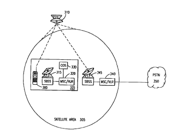
With reference now to F1GIJ'R.E 3 of the drawings, one example of call
optimization within a satellite network is the optimization of a call from a
mobile
I S subscriber to a subscriber within the Public Switched .Telephone Networi;
(PSTN) 350
(wireline network). This can be accomplished by moving the mobile subscriber's
registration to an optimum MSC/VLR 340. When a Mobile Station (MS) 300 within
an area 305 visible to a satellite 310 initiates a call to a subscriber within
the Public
Switched Telephone Network (PSTN) 350, a Mobile Switching Center/Visitor
Location Register (MSC/VLR) 320 serving the area 325 that the MS 300 is
located in
analyzes the Called Party Number (CPN) end determines thst the CPN is not a
number
registered within the serving MSC/VLR 320, The serving MSC/VLR then sends the
CPN, using, for example, an Llnstruetured Supplementary Sarvices Data (USSD)
string, to a Call Optimization Server (COS) 330 of optimization node, which
can be
co-located with the serving MSC/VLR 320. Alternatively, it should be noted
that the
COS 330 could instead be co-located with a Home Location .Register (HLR)
(shown
in FIGURE 1 ) or an external node (not shown), such as a node within the
Intelligent
Network. Tht protocol to the exiemal node could be based on an Intelligent
Network
(IN), Mobile Application Part (MAP) or other protocol.
?he COS 330 then performs a pre-analysis on the CPN to determine that the
CPN belongs to the PSTN 35D. Thereafter, the COS 330 determines the optimum
- MSC/VLR 340, ~, the MSCNLR 340 within the area 305 visible to the satellite
310
AUG-24-00 14:55 From: CA 02322268 2000-08-25
WO 99/44310
-6-
T-3t~ p.28/4T Jo6-899
i'CT/US99/04p413
that has the closest connection to the PSTN 350 or the least expensive link to
the
PSTN 350, and returns the address for this optimum MSCIVLR 340 to the MS 300
via
the satellite 310 and the serving MSCNLR 320 and satellite-adapted Base
Station
System (SBSS) 315. The MS 300 then registers with the indicated MSC/VLR 340,
and sends a SETUP messase to the new MSCIVLR 340 via the satellite 310 and the
new SBSS 345, as is understood in the art.
The call can then be completed normally usinb minimal terrestrial circuits and
existing satellite resources. Thus, the cost to the subscriber for the call
will be
reduced. This call optimization process can also be utilized for c,$Ils
between two MSs
within the aatclIitc netwrork and for calls from the PSTN to a satellite MS
subscriber.
However, such opt[mization presents a problem if the call is a mufti-party
call.
. Normally, as shown in FIGURE 4 of the drawings, for mufti-party calls, the
number
which is first called SN1 will determine which MSC/VLR 420 within the
satelli~e
coverage area 450 that the MS 400 will be registered in. Either an application
405
within the original MSC/VLR 410 serving the area 415 that the MS 400 is
located in
or the COS 330, shown in FIGURE 3, will determine the optimal MSCIVLR 420 for
the first number dialed SN 1. The MS 400 then re-registers, via satellite 460,
in the
optimal MSC/VLR 420, which can then connect the first call SN 1 to the first
called
party 425. All subsequent calls SN2, SN3 arid SN4 that are part of the mufti-
party call
will typically be made from that (optimal) MSCIVLR 420_
This presents a problem if, for example, as indicated in FIGURE 4 of the
drawings, the next three numbers SN2, SN3 and SN4 called are to subscribers
43?,
434 and 436 registered in or close to (for PSTN subscribers) a difl''erent
MSC/YLR 430
than the chosen optimal MSC/VLR 420. As can be seen in FIG1:JRIr 4, the call
co~guration for the tt~ulti-party call where the calling subscriber 400 is ro-
rcgistcrcd
in the MSCNLR 420, which øerves the area 428 (or is olosest to for PSTN calls)
for
only the first called party 425 is sub-optimal. Ideally, the re-registration
should have
been to the MSC/VLR 430 serving the area 440 (or close to for PSTN tells} that
the
last three called party's 432. 434, and 436 are located in, which would have
required
only one international link (not shown), instead of three international links
IN1, IN2
and 1N3.
CA 02322268 2000-08-25
AUG-24-OD 14:5fi From:
T-3T0 p.29/4T Job-999
Wp 99/dd310
PCT/US99roa0a8
-7-
T'hcrefore, in accordance with a first preferred embodiment of the present
invention, as shown in FIGURE 5 of the drawings, a subscriber procedure is
used to
send the entire list of parties SN1, SN2. SN3 and SN4 to the mufti-party call
to the
original MSC/VLR 510 serving the geographical area 515 that the calling MS 500
is
located in. Prior to setting up the mufti-party call, the mobile subscriber
enters a
service code, gg, '~99, an the MS 500 to indicate to the servins MSClVLR 510
that
the mobile subscriber would like to set up an optimised mufti-party call.
Thereafter.
the mobile subscriber enters each number SN1, SN2, SN3 and SN4 that wilt be
included in the mufti-party call.
The service code triggers an application 505 in the MSCNLR, which then
receives each of the telephone numbers SNl, SN?. SN3 and SN4, and consults a
database 508 within the MSCNLR 510 (vr sends the list of telephone numbers to
the
Call Optimization Server 330, shown in FIGURE 3) to determine the most optimnl
MSClVLR 530 for the mufti-party call. Many different algorithms can be used to
determine the optimal MSC/VLR 530 within the satellite coverage area 550, such
as
counting the number of different country codes received to determine which
country
was represented the most often. Ahernatively, a link-cost analysis tree could
be
utilized to determine the least-cost path.
Once the optimal MSC/VLR X30 is determined, the original MSCIVLR 510
informs the MS 500 vial the satellite 560 of the identity of the optimal
MSCNLR 530
(in case it is different than the eurrertt one). The MS 500 can then re-
register with the
optimal MSC/VLR 530 and send the same procedure string, including the list of
telephone numbers SN1, SN2, SN3 and SN4 to be dialed, without requiring the
subscriber to n-enter the telephone numbers SN 1, SN2, SN3 and SN4 for the
parties
to the mufti-party call. The optimal MSC/VLR 530 then set-up the mufti party
call by
establishing a call connection to each parry 525, 532, 534, and 536,
trspectivcly, using
thss string.
As an example, in FIGURE S, the optimal MSClVLR 530 serves the area 540
(or has the closest connection to for PSTN calls) three of the called parties
532, 534
and 536. Thus, for this example, only one international link IN4 is needed to
connect
the call to subscriber 525, which is within an area 528 served by a different
MSCNLR
CA 02322268 2000-08-25
AUG-24-00 14:56 From:
WO 99/44310
T-3T0 p.30/4T Jo6-699
PC1'/US99lOdOd8
-g-
52p. If the original MSCIVLR 500 is the optimal MSCIVLR 530, then re-
registration
is not necessary and the rnulti-party call setup can continue immediately.
In a second embodiment. after re-registration as described hereinbefore, the
MS
500 sends only the first number SNl to be dialed to the optimal MSC/VLR 530.
The
optimal MSCIVLR 530 then sets up the call to the first party 525. Thereafter,
the
subscriber must then set up the remaining calls to subscribers 532, 534, and
a36 using
conventional methods. For example, the calling subscriber can place the first
party
525 on hold, dial the number SN2 for the second party 532, and once the
connection
is made with the second party 532, can then take the frst party 525 off hold,
thus
creating a three-way call. This process continues until all parties 5?5, 532,
534 and
536 to the call have been dialed and connected. In many systems, the maximum
number of parties to tt mufti-party call 15 S1X.
In a third embodiment. the calling subscriber does not enter s service cod~
prior to entering the first number SN1 of the mufti-party call. Instead, the
original
I S MSC/VLR 510 takes the first number SN1 entered by the subscriber and
optimizes
only that call to the MSCNLR 520 serving the area 528 (or having the closest
connection to for PSTN calls) the first party 525 is in, as described
hereinbefore.
Thereafter, the rest of the mufti-party call is set up from that optimal
MSC/VLR 520
using conventional methods, However, as discussed hcreinbefore, this rnay
produce
ZO a sub-optimal mufti-party call as a whole. Therefore, after the mufti-party
call has
been set up (or alternatively, at the addition of each new subscriber), the
MSC/VLR
520 sends the dialed numbers SN1, SN2, SN3 and SN4 to the CUS 330, shown in
FIGURE 3, or io an application Sp5 within the MSC/VLR 520 to perform an
analysis
of the dialed numbers SN1, SN2, SN3 and SN4. Thereafter, the current optimal
25 MSC/VLIt S20 informs the MS 500 which party should have been called first
in order
to have ar optima) call. For instance, in the example illustrated in FIGURE 5
of the
dratwings, the optimal call would have recalled from dialing SN2 firm. Thus,
SN2
would be displayed on the display 518 of the MS 500, after dialing either SN2,
SN3,
or SN4.
30 In any cast, when the final number SN4 of the mufti-party call has been
dialed,
the subscriber will see the number SN2 on the MS display 518, which if called
first,
CA 02322268 2000-08-25
'J-04-2000
9993614;
.. ~... : .: ..
:' .. .. . .~ w:. - .;. -.. . - - . w, .-
~. . . . . ~ . : : . ~..
v . . . 1 : . ~ i.l. ~ 1 ~ i~
~ . ~ 1' ~ i i -. - 1 , ~ -~~ .
WO 99/44310 ~ '~ -9' "' '" ~'' P~T/U~S~99/04048
would have resulted in an optimal mufti-party call set-up. The current optimal
MSCIVLR 520 can send; for example, an Unstructured Supplementary Service Data
(CJSSD) message or a Short Message Service message, to the MS 500 instructing
the
MS 500 to produce short tones to attract the attention of the subscriber and
to display
the number SN2 which would have produced an optimal call. Thereafter, the
subscriber can decide whether or not to disconnect the current mufti-party
call and
reconnect beginning with the number SN2 which will produce an optimal mufti-
party
call.
In a final embodiment, after the subscriber enters the service code for
optimizing a mufti-party call and enters the numbers SN1, SN2, SN3 and SN4 to
be
dialed on the MS 500, either the COS 330, shown in FIGURE 3, or the
application 505
in the MSC/VLR 510 performs an analysis to determine the optimal MSCIVLR 530
and returns to the subscriber the number SN2 which should be called first.
Thereafter,
the subscriber can dial the optimal number SN2 returned by the original
MSClVLR
510, which then optimizes the call to the first optimal party 532 by
instructing the MS
500 to re-register with the optimal MSC/VLR 530. Once the call has been set-up
to
the first optimal party 532, the subscriber can set-up the rest of the mufti-
party call,
using conventional methods.
As will be recognized by those skilled in the art, the innovative concepts
described in the present application can be modified and varied over a wide
range of
applications. For example, it should be noted that the aforementioned mufti-
party call
optimization system and method can be utilized in any geostationary satellite
system.
AMENDED SHEET