Note: Descriptions are shown in the official language in which they were submitted.
CA 02322525 2000-08-29
WO 99/39669 PCT/RU99/00029
DEVICE FOR LASER THERAPY IN OPHTHALMOLOGY
Field of the art
The invention relates to the field of ophthalmology,namely to the laser
therapy of the eye.
State of the art
A therapeutical effect of applying an action of the laser radiation is usually
associated
with the improvement of a microcirculation of blood in the vascular system of
the eye, as
well as with direct bio-stimulation of cells. Specifically this effect is
expressed in the
increase of the visual acuity, removing a spasm of adaptation tension, which
decreases the
risk of myopia progressing and facilitates visual works at a close distance,
as well as it is
expressed in improvement of the status of the retina in case of dystrophic
changes of the
posterior section of the eye [1-3].
A stimulating transscleral action of the laser influence is strengthened by
the use of
emission of a near infrared range of the spectrum, having a greater depth of
penetration
into a tissue compared to a visible emission[l, 3]. In particular, in [3] a
method of using a
laser emission with a wave length of 1.3 m for increasing a therapeutical
effect in
treatment of different forms of retina dystrophy was offered. At the same time
when
conducting a laser therapy by infrared radiation, problems arise (because of
its
invisibility) in guiding a radiation to the selected regions of the eye. It is
important not
only from the point of view of the effectiveness of therapeutical procedures,
but their
safety as well: permissible levels of irradiating a ciliary body and retina
differ for the
orders of magnitude.
Besides, known is the use of laser radiation for curing such diseases as
retina dystrophy,
by applying to its central region an action of infrared or visible radiation.
In particular, the
method of using laser radiation with a wave length of 1.3 m for raising a
therapeutical
effect during treatment of different forms of retina dystrophy was suggested
in [3].
Known is the device for laser therapy in ophthalmology [1, 4], containing two
optical
units with lasers for affecting a prelimbic region of the eye by light
emission and forming
CA 02322525 2000-08-29
optics, as well as a power unit and control unit, equipped with a timer for
setting the time
of radiation are known. These optical units are fixed in a rim in the form of
"spectacles",
and the device additionally contains an adjustment mechanism, on which a
laser, light
emitter and forming optics of each of such optical units are installed with a
possibility of
displacement (adjustment) with respect to the visual axis of the eye. This is
required for
coordinating the positioning of optical units with regards to the
interpupillary distance of
a patient. In this device a light emitter (light diode) is used as a bench
mark, and with a
help of a forming optics it forms a luminous precision mark at which a sight
of a patient
is fixed. This mark glitters during the work of lasers, set by the timer.
During this period
of time the radiation from lasers is focused in a ciliary muscle field of
projection upon
sclera at 3 and 9 hours, applying an action upon the ciliary body.
However, the solution of the above task in this device, although provides for
the safety of
laser therapy, but decreases its efficiency because of undesirable side
effects. This is
related to possible excessive visual tension, arising during the concentration
of attention
of a patient at glittering mark from the light emitter during the whole
therapy sitting,
which in a number of cases causes weariness and discomfort, and brings about
the
reduction of the effectiveness of the therapeutical effect of a laser
radiation. Such
undesirable manifestations appear in particular in the patients having a
weakened
convergence, high degree myopia and hypermetropia, asthenopia, as well as in a
general
case in small children. For such patients the necessity to fix a sight at
luminous marks,
located nearby, for rather a long period of time can cause a visual
overstrain. Hence the
need of such solution of the task of keeping a sight of a patient in the
required direction,
at which the above undesirable manifestations are absent or substantially
reduced.
Essence of Invention
The technical task of the invention is raising the efficiency of laser therapy
and reducing
discomfort for a patient during it by forming a vision channel by way of local
reduction of
a patient's field of vision in the required direction. By that, in the absence
of closely
located objects of observation, at which the attention of a patient is
concentrated
(glittering luminous marks), the eye is in a comfortable state and nothing
contributes to
the creation of an accommodation tension, bringing about the above undesirable
manifestations. At the same time because of its locality in a transverse
direction (which is
shown by the term "channel" itself), the vision channel is keeping a sight of
a patient in
2
CA 02322525 2000-08-29
the required direction. It is preferable that this direction coincides with a
vision axis of the
eye.
In addition to that the task of applying a combined action upon prelimbic
regions of the
eye and upon its central part is solved. Thus, a possibility is revealed to
use the suggested
device not only for the stimulation of the ciliary muscle by applying an
action of laser
emission upon prelimbic regions of the eye, but in particular, also for
treating such
diseases as retina dystrophy, by affecting its central area by infrared or
visible radiation,
while the retina therapy and ciliary body stimulation can be performed
simultaneously.
The task put is solved by making a device for laser therapy, containing at
least one optical
unit, including one or several lasers and forming optics for applying an
action of laser
emission upon one or several regions of prelimbic area of the eye, as well
means for
fixing a patient's sight in the specified direction, while the above means is
made in the
form of a local field of vision limiter, forming a vision channel, and the
forming optics is
installed into the position with respect of the vision channel that provides
for laser
emission hitting the prelimbic region of the eye during the fixation of the
sight of the
patient in the direction, specified by the vision channel.
In the binocular embodiment of the device, i.e. when using two above optical
units for
binocular effect, it additionally contains an adjustment mechanism, in which
the above
optical units are installed with a possibility of their displacement in
respect of each other
in the direction transversal to their axes for mutual setting of vision
channels of these
optical units in accordance with individual interpupillary distance of a
patient.
In specific cases of the embodiment, the local field of vision limiter is made
in the form
of a diaphragm or telescopic system.
In order to provide for the possibility of a combined action upon a central
region of the
retina and ciliary body in one apparatus, with a simultaneous therapy of a
retina and
ciliary body stimulation, the device additionally contains one or several
sources of
infrared or visible radiation, optically coupled with the vision channels of
the optical units
for applying an action to the central region of the retina.
For providing a possibility of a stimulating action upon the sensory apparatus
of the eye,
characteristic of the observation of the laser emission speckles pattern,
which contributes
to increasing the visual acuity and complements the spectrum of combined
influence of
3
CA 02322525 2000-08-29
laser emission upon the eye apparatus, expanding functional and treatment
possibilities of
the device, the above source for applying an action upon the central region of
the retina is
the source of visible laser radiation, optically coupled with a vision channel
or vision
channels with a help of a structure for the shaping of a regular or random
interference
pattern.
The structure for the shaping of a regular or random interference pattern can
be made in
the form of a difraction grid or a diffusing structure.
In a particular case of the embodiment, the above source for applying an
action upon the
prelimbic region of the retina is the source of visible laser emission,
optically coupled
with the vision channel or vision channels with a help of a scattering screen
which is
additionally introduced into the device composition.
In a different specific embodiment, each optical unit has one of lasers
additionally
coupled with the vision channel of this unit through a beam splitter for
applying an
action upon the central region of the retina as well, while the intensity of
radiation
affecting the central retina region is of three orders of magnitude less than
the intensity of
the laser.
In particular, the beam splitter is made in the form of glass or quartz
plates, or semi-
transparent mirrors.
Brief description of the drawings
The essence of the invention described above is explained with the concrete
examples of
its embodiment with the use of the diaphragm as the patient's field of vision
limiter.
Fig. 1-3 shows optical schemes of the device for laser therapy in
ophthalmology for
different variants of combined action upon the prelimbic region of the eye and
central
retina region: with the use of an additional separate infra red or visible
radiation source in
monocular embodiment (fig. 1) or binocular embodiment (fig. 2), or with the
use of one
of lasers as this source (fig. 3).
4
CA 02322525 2000-08-29
Variants of the invention embodiments
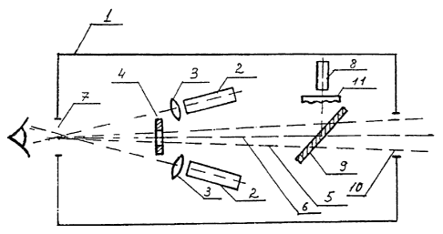
The device for laser therapy in ophthalmology comprises (fig. 1) an optical
unit 1 with
two lasers 2 (semiconductor lasers), each of which is equipped with the
forming optics
(3) (in the form of a lens, installed on the axis of this laser) and serves
for applying an
action of a laser radiation upon a corresponding area (is not shown in fig. 1)
of the
prelimbic region of the eye (shown conventionally). The optical unit 1
additionally
comprises the local field of vision limiter (for example, in the form of a
diaphragm) for
forming the vision channel 5, assigning the direction of a patient's sight.
Diaphragm 4
(with the diameter of an opening of 3 mm) is located in the optical unit 1 on
one axis,
being axis 6 of optical unit 1, with the inlet aperture 1(inlet opening or
ocular) of this
unit meant for the observation at the distance of 25 mm from aperture 7 by the
patient
during the sitting. Lasers are located at both sides of diaphragm 4,
symmetrically with
respect to axis 6 of optical unit I for irradiating areas of the prelimbic
region at 3 and 9
hours. By that, the axis of the vision channel and directions, at which a
laser radiation
affects the eye, should not be by all means collinear.
Besides, optical unit I can contain source 8 of a visible laser radiation (He-
Ne laser),
optically coupled with vision channel 5 of unit 1 so as to apply an action to
the central
region of the retina. The coupling is made with a help of a semitransparent
mirror 9,
installed on the axis of source 8 and of vision channel 5 at coordinated
angles. The
transmission ratio of the mirror 9 is selected so that the patient is not
prevented from
observing a distant object through outlet aperture 10 of optical unit 1. It is
further possible
to include a diffused dispersion structure 11 (opaque glass) on the axis of
source 8
between it and mirror 9, allowing the patient to observe a speckle diagram
formed by the
laser beam emitted from source 8.
The device offered can be made both in a monocular, and in a binocular
version. In
difference from the monocular device shown in fig. 1, the binocular device of
fig. 2 uses
one laser 2 each with the forming optics. Besides, source 8 is introduced for
all the device
as a whole and it is optically coupled with vision channels 5 of the first and
the second
optical units 1 with a help of semi-transparent mirrors 9. The patient is
looking with both
eyes through two inlet apertures 7, diaphragms 4, mirrors 9, outlet apertures
10 at the
remote object, located in the field of vision, limited by channels 5 of both
units 1. The
CA 02322525 2000-08-29
peculiarity of the device of fig. 2 is that the optical scheme of vision
channels 5 is made
polygonal in such a way that outlet apertures 10 of optical units 1 are
shifted towards each
other compared to inlet apertures 7. For optical unit I this is made with a
help of the
system of two mirrors 12 and 13, inclined to axis 6 of this unit and separated
in the
direction, transversal to this axis 6, one of which facing the inlet aperture
7, and the other-
outlet aperture 10.
In the device for binocular effect the outlet apertures 7 of optical units 1
can be dispalced
towards each other, i.e. the distance between them in transversal direction
can be less,
than an interpupillary distance of a patient's eye. This gives a possibility
to bring the risk
of the above undesirable manifestations with the patients to a minimum .
The device for a binocular effect can additionally contain an adjustment
mechanism, in
which the above optical units with local field of vision limiters are
installed with a
possibility of their positioning with respect to each other in the direction,
transversal to
their axes (for example, as in opera glasses) for mutual alignment of visual
channels of
these optical units in accordance with the individual interpupillary distance
of the patient.
In fig. 3, laser 2 is used as source 8 (see fig. 1), for which it is
additionally optically
coupled with vision channel 5 of this unit through beam splitter for applying
also an
action upon the central region of the retina. This beam splitter is made in
the form of a
system of two semi-transparent optically coupled mirrors 14 and 15, one of
which (14) is
facing inlet aperture 7 of optical unit 1, and the other - laser 2.
Constructively, diaphragm 4 can be made, for example, in the form of a plate
looking like
a strip with a hole in the indicated axis of the optical unit, at one or each
side of which
one or two lasers (for example, laser diodes) with forming optics at each are
installed
(and fixed in the body of the unit similar to the diaphragm). If the diaphragm
in the form
of a disk is used, then (if required) additional openings for radiation
passing from lasers
to irradiated regions of the eye should be made. Diaphragm 4 can be installed
in the body
of unit 1 with the possibility of its displacement along its plane (for
assigning the required
direction for the vision channel) and of fixing it in the selected position.
Of course, other
embodiment of the local field of vision limiter is possible, in the form of a
lens or mirror
telescopic system, restricting the patient's field of vision in proportion to
magnification.
The inlet aperture of the optical unit shall in this case be located on the
axis of this
system, being the axis of the optical unit in such embodiment of the field of
vision
6
CA 02322525 2000-08-29
limiter. The aperture of the telescopic system, its positioning in the unit,
are determined
based on the condition of providing the field of vision of the order of 3-6
degrees.
Going beyond the above limits of the angular size of the field of vision is
also possible. It
can be limited at the bottom by a minimum angle, at which the eye can still
differentiate
the object without special tension. At the top it can be limited by the angle,
at which
irradiation from lasers cannot yet hit the pupil of an eye when it moves
within the field of
vision.
Hence, it becomes clear that the availability of the field of vision limiter
itself is essential
for the invention, but not a specific form of its embodiment.
Different variants of the use of the visions channel for applying an action
upon the central
region of the retina are possible. In one of them each optical unit 1
additionally comprises
source 8 of infrared or visible radiation (for example, laser), optically
coupled with the
vision channel of this unit. In the other variant - one or several of such
sources are
introduced additionally for the whole of the device and they are optically
coupled with the
vision channel of all (one or two - in case of the binocular device) optical
units. One of
lasers, additionally optically coupled with the vision channel of this unit
through a beam
splitter for diverting part of its radiation to the central region of the
retina can be used as
such source in each optical unit. The intensity of the coupled radiation
should be less than
the intensity of lasers radiation for approximately three orders of magnitude.
That is why
the beam splitter can be made in the form of a system of two thin flatly
parallel optically
coupled glass or quartz plates. One of them is installed in the axis of a
laser, inclined to it,
and the other- is similarly located on the axis of the optical unit.
Semitransparent optically
coupled mirrors (with the transmission ratio of the same order), one of which
is facing the
inlet aperture of the optical unit, and the other - laser, can be used instead
of the plates.
Such a coupler will not interfere with the execution of the main function by
the device -
laser stimulation of the ciliary muscle while keeping the sight of the patient
in the
required direction with a help of the vision channel.
The schemes of an optical coupling of the source with the vision channel
(channels)
described are given for illustration. It is only the presence of the optical
conjugation for
providing the influence of laser radiation upon the central retina region,
alongside with
the influence upon the prelimbic region of the eye , that is essential for the
indicated
variants of the device embodiments, and not the form of its specific
embodiment.
7
CA 02322525 2000-08-29
Especially attractive is the possibility of using the source of visible laser
radiation, which
is optically coupled with the vision channel of one optical unit or vision
channels of both
the optical units with a help of the structure for forming a regular or random
interference
pattern. In particular, a diffraction grid or diffused scattering structure
(for example,
opaque glass) can correspondingly be used as such structure. In the latter
case the pattern
of speckles of laser emission itself, formed as a result of scattering by
diffused media, is
the object of observation for the patient. By that, a distinct interference
pattern is created
on the retina, irrespective of the status and pathology of the optical
apparatus of the eye.
For the perception of such pattern, the patient does not have to exert tension
upon the
accommodation system of the eye, which can be completely relaxed. For the
observation
of the pattern of laser radiation speckles in the process of laser therapy,
the above
scattering structure can be placed, for example, between the source and
inclined mirror,
serving for an optical coupling of the source with the vision channel. It is
necessary to
point out once again that the pattern of speckles, observed in the field of a
visible
channel, can play the role of an observation object for patient's sight
fixation.
Such variant of the device is also possible, when an additional source of
laser emission
for affecting the central region of the retina is made in the form of a
separate unit, and its
optical coupling with vision channels of optical units is performed with a
help of a
scattering screen, additionally introduced into the device composition,
located in the field
of vision of a patient.
The device functions in the following way. The patient is offered to look
through inlet
aperture 7 at a remote object (is not shown in the figure), located beyond the
outlet
aperture 10, or at the pattern of speckles, formed by the diffused scattering
structure 11.
Even more so, the patient fixes his sight in such a way that the object or
pattern of
speckles are found in the centre of the field of vision. After that lasers 2
are switched on.
Emission from lasers 2, shaped by the forming optics 3, because of the setting
of the
direction of the patient's sight with a help of the vision channel 5, formed
by diaphragm
4, is supplied simultaneously to two areas of the prelimbic region of the eye,
located at 3
and 9 hours, in the form of spots with the distance between the centres of
about 14 mm.
The duration of a laser therapy session, similarly to what was done in [1], is
assigned by a
timer (not shown in fig. 1) and usually constitutes from 2 to 5 minutes. When
therapy of
the retina is needed, source 8 is connected, the irradiation of which is
directed with a help
of mirror 9 to its central region along vision channel 5 through inlet
aperture 7. Control of
the operation of source 8 is performed by a separate timer ( not shown in fig.
1). Upon the
8
CA 02322525 2000-08-29
expiration of the time set, the timers switch off lasers 2 and source 8. The
timers work
irrespective of each other. If synchronisation of their work is required, then
the use of the
device according to the scheme of fig. 3 is preferable, where laser 2
simultaneously
performs the functions of source 8. The control of the operation of emitters 2
and source
8, carried out through the power unit and control unit (are not shown in fig.
1) with a help
of the above timers is not an essential peculiarity of the invention, and
cannot limit it
because of that. So, it is possible to interrupt the supply of radiation to
the prelimbic
regions of the eye and to the central region of the retina with a help of
corresponding
shutters (for example, electronic shutters) at the outlet of lasers 2 and
source 8.
When the device is used in the binocular version (fig. 2), the work of the
optical units 1 is
performed in a similar way. The difference is that before the beginning of a
sitting a
patient, with a help of an adjustment mechanism (not shown in fig. 2), moves
these
optical units 1 with diaphragms 4 with respect to each other in the direction
transversal to
their axes 6 for mutual setting of vision channels 5 in accordance with his
individual
interpupillary distance. The patient determines it according to the merging of
observation
objects, visible by each eye. At that, an exact matching of the visual axes of
both eyes
with optical axes 6 of units 1 takes place. After that the described above
combined action
can be conducted simultaneously for both eyes of the patient.
For confirming the possibility of implementing the invention and providing for
high
efficiency of laser therapy of accommodation system of the eye pathologies, a
specific
example of the concrete application of the device according to the invention
is given.
Patient K., 10 years old. Diagnosis - progressing myopia. The acuity of vision
for both the
eyes without correction is equal to 0.1, with spl - 2.5 Diopters is 0.9. The
reserve of the
relative accommodation is equal to - 2.0 Diopters. The patient had the course
of laser
therapy during 10 days. The influence was monocular upon the prelimbic region
of the
eye in the region of 3 and 9 hours by infrared radiation with the wave length
of 1.3 m. A
combined dose of irradiation is 0. 2 J/sm2. The irradiation of the prelimbic
region was
combined with a simultaneous observation for a laser speckle structure through
the vision
channel, formed by a diaphragm.
As a result of treatment the reserve of the relative accommodation was
increased to 4.0
Diopters. The acuity of the vision of both eye without correction became equal
to 0.2,
with spl - 2.0 Diopters it constituted 1Ø
9
CA 02322525 2000-08-29
Industrial applicability
The invention may be used in conducting a laser stimulation of the ciliary
muscle for
raising the efficiency of therapy of the eye accommodation system pathologies,
expressed
in the improvement of the adaptation capacity of the eye, its visual functions
and visual
efficiency, as well as for reducing discomfort in the process of such therapy
and
decreasing the risk of undesirable side effects. Besides, it allows to
implement a
combined action of a laser beam: transscleral action upon the ciliary body,
and,
simultaneously, action upon the central region of the retina, which
contributes to the
improvement of blood circulation in the vascular layer, improvement of the
function of
the retina and of sensory apparatus as a whole, as well as permits to optimise
the
procedure of such influence with respect to a specific patient.
LITERATURE
1. E.B. Anikina, E.I. Shapiro, N.B. Baryshnikov, L.S. Orbachevsky, T.A. Pikus.
Laser
Infrared Therapeutical Device for Treatment of Disorders of the Adaptation
Capacity
of the Eye. Thesis of the reports at the 8-th Conference "Laser Optics" and 15-
th
Inteinational Conference on Coherent and Non-Linear Optics, S-P, 1995.
2. V.E. Avetisov, E.B. Anikina, E.V. Akhmedzhanova. The use of helium - neon
laser in
functional research of the eye and in pleoptical treatment of amblyopia and
nystagmus.
Methodological recommendations of the Ministry of Health of the RSFSR, MNIIGB
named after Helmgolts, M., 1990, 14 pages.
3. L.A. Katsnelson, E.B. Anikina, G. Yu. Zakharova, E. Sh. Shapiro
The application of low energy infrared laser emission for the improvement of
blood
circulation and increasing the vision function with the patients having retina
disorders.
Methodological manual for physicians. Ministry of Health and Ministry of
Education of
the RF, Moscow Scientific Research Institute named after Gelmgolts, M., 1996,
7 p.
4.Patent RU N 2092140, A 61 F 9/00