Language selection

Search

Patent 2322693 Summary

Third-party information liability

Some of the information on this Web page has been provided by external sources. The Government of Canada is not responsible for the accuracy, reliability or currency of the information supplied by external sources. Users wishing to rely upon this information should consult directly with the source of the information. Content provided by external sources is not subject to official languages, privacy and accessibility requirements.

Claims and Abstract availability

Any discrepancies in the text and image of the Claims and Abstract are due to differing posting times. Text of the Claims and Abstract are posted:

  • At the time the application is open to public inspection;
  • At the time of issue of the patent (grant).
(12) Patent: (11) CA 2322693
(54) English Title: AN ARRANGEMENT FOR DRILLING SLOTS
(54) French Title: SYSTEME PERMETTANT DE FORER DES FENTES
Status: Deemed expired
Bibliographic Data
(51) International Patent Classification (IPC):
  • E21C 25/58 (2006.01)
  • E21B 4/00 (2006.01)
  • E21B 7/00 (2006.01)
  • E21B 7/28 (2006.01)
  • E21B 19/24 (2006.01)
  • E21D 9/10 (2006.01)
(72) Inventors :
  • HORMAN, MAGNUS (Sweden)
(73) Owners :
  • WASSARA AKTIEBOLAG (Sweden)
(71) Applicants :
  • G-DRILL AB (Sweden)
(74) Agent: RIDOUT & MAYBEE LLP
(74) Associate agent:
(45) Issued: 2006-12-19
(86) PCT Filing Date: 1999-02-23
(87) Open to Public Inspection: 1999-09-10
Examination requested: 2003-11-21
Availability of licence: N/A
(25) Language of filing: English

Patent Cooperation Treaty (PCT): Yes
(86) PCT Filing Number: PCT/SE1999/000244
(87) International Publication Number: WO1999/045237
(85) National Entry: 2000-08-31

(30) Application Priority Data:
Application No. Country/Territory Date
9800647-1 Sweden 1998-03-03

Abstracts

English Abstract


A down-hole rock drilling machine (in-hole rock drilling machine) has a
carrier sleeve (22) mounted in combined axial and radial
bearings (21, 22 and 23, 24) and the carrier sleeve carries a guiding tube
(30) laterally of the machine with an element (31) inbetween. The
bearings (21, 22 and 23, 24) and the carrier sleeve (22) are held axially
together between a shoulder (17) on the machine housing (11) and
a drill bit holding sleeve (13). The machine housing will be subjected to
strong vibrations, but since the bit holding sleeve (13) is screwed
to the machine housing (11) and transmits the rotation to the drill bit (14),
the carrier sleeve bearing arrangement will be second.


French Abstract

Une perforatrice de roches fond de trou (une machine de forage de roches située dans le fond du trou) comprend une gaine porteuse (22) montée dans des paliers porteurs mixtes axiaux et radiaux (21,22 et 23,24), la gaine porteuse supportant un tube (30) de guidage sur le côté latéral de la machine avec un élément (31) intercalé dans l'espace intermédiaire. Les paliers (21,22 et 23,24) et la gaine porteuse (22) sont maintenus ensemble de manière axiale entre un épaulement (17) prévu sur le carter (11) de la machine et un manchon (13) de retenue du trépan. Le carter de la machine est soumis en utilisation à de fortes vibrations, mais étant donné que le manchon (13) de retenue du trépan est vissé sur le carter (11) de la machine et transmet la rotation au trépan (14), le système de palier de la gaine porteuse est bien fixé.

Claims

Note: Claims are shown in the official language in which they were submitted.


-4-


Claims

1. An arrangement for drilling slots, said arrangement characterised by:
a down-hole rock drilling machine having a machine housing and a drill bit,
a carrier sleeve journaled on the machine housing to permit rotation of the
machine in the carrier sleeve,
a guiding element fixed to and carried by the carrier sleeve laterally thereof
and arranged to be guided by a predrilled borehole during a drilling
operation,
axial bearings for the carrier sleeve on the machine housing, and
a machine part for holding the axial bearings axially in place, said machine
part being fixed to the machine housing by a thread connection subjected to
the torque for rotating the machine during drilling.
2. An arrangement according to claim 1, characterised in that said machine
part
is a bit holder which has a splined connection to the drill bit.
3. An arrangement according to claim 1 or 2, characterised in that the guiding
element is a tube, said tube being plugged at a front end thereof.
4. An arrangement according to any one of claims 1 to 3, characterised by an
intermediate element between the machine and the guiding element, a front
surface of the intermediate element having an angle to the machine housing
of between 10 and 45 degrees.

Description

Note: Descriptions are shown in the official language in which they were submitted.


CA 02322693 2000-08-31
WO 99/45237 PCT/SE99/00244
An arrangement for drilling slots
This invention relates to an arrangement for drilling slots with a down-hole
rock drilling
machine. Such machines move into the borehole.
Such drilling of slots by means of a top hammer (a rock-drilling machine
outside of the
borehole) is known for example from SE-B-420435.
It is an object of the invention to make possible the drilling of slots also
by using a down
hole drilling machine and the invention has been given the characteristics
defined in the
claims.
The invention will be described with reference to the accompanying drawings.
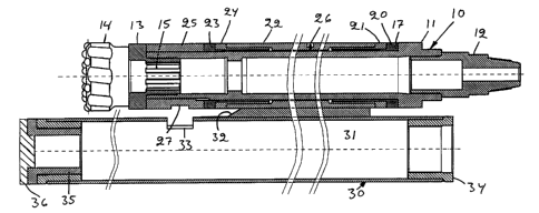
Figure 1 shows, in a longitudinal section, an arrangement for drilling slots
in rock as an
example of the invention.
Figure 2 shows, in a transverse section, a slot bored with the arrangement
shown in figure 1.
Figure 1 shows a rock-drilling machine with a housing 10 that comprises a
machine tube 11,
a backhead 12 screwed to the machine tube 11, and a drill bit holding sleeve
13 screwed to
the machine tube. The bit holding sleeve 13 is in splined connection with the
shank 15 of the
drill bit 14 and the drill bit is limitedly movable axially in the sleevel3.
Inside the machine
housing there is a non-illustrated piston hammer and a valuing arrangement for
driving the
hammer piston so that it will impact on the end face of the drill bit shank 15
with a
frequency of 50-100 Herz. The drive medium for driving the piston hammer can
be a
pressure fluid such as compressed air or a pressurised liquid, for example
water,
conventionally supplied through the non-illustrated drilling tube to which the
backhead 12 is
screwed. The spent drive fluid exits through channels in the drill bit head
and is used as a
flushing fluid for hushing away the debris.
The machine tube 11 has a shoulder 17 and between the shoulder 17 and the
drill bit holding
sleeve 13 are axially held: a bearing that comprises two sleeves 20,21, a
carrier sleeve 22, a
bearing that comprises two sleeves 23,24, and a distance holding sleeve 25
that has a splined

CA 02322693 2006-03-22
2
connection to the machine tube 11. The Garner sleeve 22 has a clearance to the
machine
housing 1 l and it has a lubricant nipple 26 through which lubricant can be
supplied to the
clearance for lubricating the bearings 20,21 and 23,24. The sleeves 20,23 of
the bearings
have radial fit to the machine housing 11 so that they rotate with the housing
whereas the
sleeves 21,24 of the bearings have radial fit to the carrier sleeve 22 so that
they do not rotate
with the machine tube 1 I. Thus the bearings 21,22 and 23,24 serve both as
radial bearings
and axial bearings for the carrier sleeve 22 on the machine tube 11.
Since the bit holding sleeve 13 transmits the torque to the drill bit during
drilling, there is no
risk that the bearings for the carrier sleeve 22 should loosen because of the
vibrations. The
distance holding sleeve 25 has key grips 27 to permit for breaking of the
thread between the
machine tube 11 and the bit holding sleeve 13. The splined connection between
the distance
holding sleeve 25 and the machine housing 11 is there to permit for such a
breaking.
The carrier sleeve 22 carries an elongate tubular guiding element 30 through
an intermediate
element 31 that is welded both to the guiding tube 30 and to the carrier
sleeve 22. The front
end of the intermediate element 31 forms an inclined breaking surface. The
guiding tube has
an opening 33 arranged to make it possible to reach the key grip 27 with a key
or spanner.
The rear end of the guiding tube 30 has a bushing 34 welded to it and the
bushing has an
interior thread to which an extension can be mounted when the rock is
incompetent and a
long guiding element is necessary. The front end of the guiding tube 30 has a
similar
bushing 35 welded to it and the bushing is plugged by a plug 36.
When a compressed air driven downhole drilling machine is used, a suction hose
from a
vacuum cleaner can be coupled to the bushing 34. Then the debris is sucked
into the guiding
tube 30 through the hole 33.
When drilling a slot, the operator drills a first borehole with a down-hole
drilling machine
that has a machine housing 10 with an even outer tubular surface, that is, a
housing without
a carrier sleeve 22. With the arrangement shown in figure l, he then drills a
hole at the side
of the first hole and with the guiding tube 30 guided by the first hole.
Usually, the rock
between the two holes will crack continuously by the forces resulting from the
movement of

CA 02322693 2000-08-31
WO 99/45237 PCT/SE99/00244
3
the drill bit 14. In this way the operator can continue to drill hole by hole
so that a slot will
result. Figure 2 shows a three-hole slot.
When the drill bit becomes worn so that its diameter is reduced, it may occur
that the wall
between two holes does not break by itself. Then, the inclined front surface
32 of the
intermediate element 31 will break this wall and because the surface is
adjacent the machine
housing, there will be a transverse resultant force on the surface 32 which
forces the drill bit
towards the pilot hole. This transverse force will prevent a continually
increased wall
thickness and thereby, it will prevent the drilling arrangement to get stuck.
The angle
between the inclined surface 32 and the carrier sleeve 22 should preferably be
between 10
and 45 degrees. The guiding tube 30 should have a diameter that is so much
smaller than the
nominal diameter of the drill bit that the normal wear on the diameter of the
drill bit will not
cause the machine to get stuck. The diameter of the guiding tube can for
example be 203
mm if the nominal diameter of the drill bit is 211 mm.
In stead of using the bit holding sleeve 13 for axially securing the bearings
20,21;23,24 and
the carrier sleeve 22, one could use the backhead 12 since the thread
connection between the
backhead 12 and the machine housing 10 transmits the same torque as does the
thread
connection between the bit holding sleeve 13 and the machine tube 11.
One field of use for the described slot drilling arrangement is the drilling
of opening slots in
tunnel driving and raise driving. When driving a raise, one can for example
drill 40 m long
slots and then blast the entire 40 meters in a single blast.

Representative Drawing
A single figure which represents the drawing illustrating the invention.
Administrative Status

For a clearer understanding of the status of the application/patent presented on this page, the site Disclaimer , as well as the definitions for Patent , Administrative Status , Maintenance Fee  and Payment History  should be consulted.

Administrative Status

Title Date
Forecasted Issue Date 2006-12-19
(86) PCT Filing Date 1999-02-23
(87) PCT Publication Date 1999-09-10
(85) National Entry 2000-08-31
Examination Requested 2003-11-21
(45) Issued 2006-12-19
Deemed Expired 2011-02-23

Abandonment History

There is no abandonment history.

Payment History

Fee Type Anniversary Year Due Date Amount Paid Paid Date
Application Fee $300.00 2000-08-31
Maintenance Fee - Application - New Act 2 2001-02-23 $100.00 2001-02-12
Registration of a document - section 124 $100.00 2001-03-05
Maintenance Fee - Application - New Act 3 2002-02-25 $100.00 2001-12-03
Maintenance Fee - Application - New Act 4 2003-02-24 $100.00 2003-01-10
Maintenance Fee - Application - New Act 5 2004-02-23 $150.00 2003-11-17
Request for Examination $400.00 2003-11-21
Registration of a document - section 124 $100.00 2003-11-21
Maintenance Fee - Application - New Act 6 2005-02-23 $200.00 2004-11-01
Maintenance Fee - Application - New Act 7 2006-02-23 $200.00 2005-12-06
Final Fee $300.00 2006-10-02
Maintenance Fee - Application - New Act 8 2007-02-23 $200.00 2006-11-17
Maintenance Fee - Patent - New Act 9 2008-02-25 $200.00 2007-11-05
Maintenance Fee - Patent - New Act 10 2009-02-23 $250.00 2008-11-17
Owners on Record

Note: Records showing the ownership history in alphabetical order.

Current Owners on Record
WASSARA AKTIEBOLAG
Past Owners on Record
G-DRILL AB
HORMAN, MAGNUS
Past Owners that do not appear in the "Owners on Record" listing will appear in other documentation within the application.
Documents

To view selected files, please enter reCAPTCHA code :


To view images, click a link in the Document Description column. To download the documents, select one or more checkboxes in the first column and then click the "Download Selected in PDF format (Zip Archive)" or the "Download Selected as Single PDF" button.

List of published and non-published patent-specific documents on the CPD .

If you have any difficulty accessing content, you can call the Client Service Centre at 1-866-997-1936 or send them an e-mail at CIPO Client Service Centre.


Document
Description 
Date
(yyyy-mm-dd) 
Number of pages   Size of Image (KB) 
Representative Drawing 2000-12-01 1 14
Abstract 2000-08-31 1 62
Description 2000-08-31 3 152
Claims 2000-08-31 1 34
Cover Page 2000-12-01 1 54
Drawings 2000-08-31 2 93
Description 2006-03-22 3 150
Claims 2006-03-22 1 28
Representative Drawing 2006-08-25 1 25
Cover Page 2006-11-21 1 58
Correspondence 2000-11-17 1 23
Assignment 2000-08-31 2 113
PCT 2000-08-31 9 353
Assignment 2001-03-05 2 103
Fees 2003-01-10 1 31
Fees 2001-12-03 1 32
Prosecution-Amendment 2003-11-21 1 47
Assignment 2003-11-21 3 213
Fees 2003-11-17 1 31
Fees 2007-11-05 1 28
Correspondence 2006-10-02 1 26
Prosecution-Amendment 2006-02-24 2 71
Fees 2001-02-12 1 43
Fees 2004-11-01 1 28
Fees 2005-12-06 1 26
Prosecution-Amendment 2006-03-22 5 172
Fees 2006-11-17 1 29
Fees 2008-11-17 1 35