Note: Descriptions are shown in the official language in which they were submitted.
CA 02322791 2000-09-O1
WO 99/48194 PCT/US98/05359
1
ELECTRIC MOTOR MONITORINC3 CIRCUIT
1 BACKGROUND OF.THE INVENTION
2 . 1~
3 The present invention relates to an electric
4 motor and electric motor monitoring circuit and
especially to an electric motor monitoring circuit
6 which monitors insulation leakage of an electric motor
7 and monitors phase sequence and voltage amplitude to
8 inhibit the operation of the electric motor which does
9 not pass phase or insulation testing.
In the past, insulation testers have been
11 installed on electric motors to protect expensive
12 equipment in the event of an insulation breakdown,
13 such as might occur from old age, partial burnout, or
14 moisture penetration into the motor housing. An
insulation tester blocks out the motor's operation if
16 the insulation resistance is below a set resistance
17 and may also energize an alarm relay. A good example
18 of an insulation testing circuit can be seen in our
19 prior U. S. patent, No. 4, 716, 487 to Horvath et al. ,
for an apparatus for monitoring motor winding leakage.
21 This system automatically monitors the insulation
22 leakage resistance of an electric motor for a short
23 period prior to operation thereof and has timing means
w 24 for delaying application of the motor control voltage
to the motor and for applying an high voltage direct
26 current to the windings of the motor during this short
27 period. A sensing resistor is connected between the
28 motor frame and the high voltage supply ground and the
29 leakage current therethrough is monitored by a
comparator. Wher~ the leakage current exceeds a
31 preselected threshold, an alarm is initiated and
32 operation of the motor is inhibited.
CA 02322791 2000-09-O1
WO 99/48194 PCT/US98/05359
2
1 Phase monitors have also been installed in
2 connection with electric motors to monitor three phase
3 power line for anomalies to determine power line
4 disruptions, such as phase loss, phase imbalance,
phase reversal, and low or high voltage, while the
6 motor is operational. A power line problem can cause
7 extensive damage to equipment over a period of time.
8 Phase loss alone can burnout an expensive motor beyond
9 repair in less than 24 hours. Such monitors operate
continuously during the operation of the motor while
11 the monitoring of motor winding leakage is normally
12 tested prior to starting of the motor. A typical
13 three phase monitor circuit can be seen in the Grant
14 patent, No. 4,823,227. Solid state circuitry is
designed to protect three phase electrical equipment
16 operating from 240 to 480 volts for loss of any phase,
17 phase reversal, or under voltage or over voltage of
18 the power supply. If the phasing or voltage in the
19 motor are correct, the motor will energize an output
relay to enable the load to operate the protected
21 equipment.
22 Other prior U.S. patents relating to monitoring
23 of an electric motor circuit or the like include the
24 Schuyler patent, No. 5,315,256, for a fault detection
circuit for use in determining the existence of a
26 fault in any one of a plurality of DC loads and uses
27 a reference load as a benchmark. The center points of
28 the loads being monitored are compared with the
29 voltage of the center point of the reference load.
The Lee patent, No. 5,239,439, is a protection circuit
31 for a power supply system. The Tran et al. patent,
32 No. 5,224,010, is a power supply supervisor with
33 independent power-up delays. The Izaguirre, Sr.
34 patent, No. 4,825,328, is a three phase electrical
CA 02322791 2000-09-O1
WO 99/48194 PCTJUS98/05359
3
1 load protection device which has an input transducer
2 for protecting each phase voltage in the direction of
3 rotation of the phases of a three phase power system.
4 A control monitor monitors signals from the input
transducer representative of the highest and lowest
6 phase voltage in the direction of the rotation of the
7 phases for controlling an output device for
8 disconnecting the electric load when improper supply
9 conditions are detected. The Hsieh patent, No.
4,507,713, is a wide range multiphase undervoltage
11 detection circuit which detects a multiphase input
12 voltage compared to a reference voltage. The
13 Schoenmeyr patent, No. 4,333,119, is a power monitor
14 system which monitors electrical three phase power in
order to protect three phase equipment from excessive
16 variations in line voltage, phase-to-phase unbalanced
17 and reverse phase sequencing and to protect personnel
18 against the automatic restart of equipment upon return
19 of line power. The Yeasting patent, No. 4,333,050,
teaches a multiphase voltage monitor which
21 continuously compares the voltage on each phase of the
22 power line with a reference voltage to detect voltage
23 unbalance and with fixed voltages to detect high or
24 low voltage conditions.
The present invention is for an electric motor
26 monitoring circuit which monitors electric motor
27 insulation leakage and power line disruptions, such as
28 phase loss, phase imbalance, phase reversal, and low
29 or high voltage, while the motor is operational and
will prevent the operation of the motor in the event
31 of a predetermined measured motor winding leakage and
32 will stop the operation of an operational electric
33 motor upon measuring of predetermined phase loss
34 unbalance or reversal or a high or low voltage.
CA 02322791 2000-09-O1
WO 99/48194 PGT/US98/05359
4
1 SUMMARY OF THE INVENTION
2
3 An electric motor monitoring circuit apparatus
4 for an electric motor has a three phase electric motor
having an electric motor starter circuit. An
6 insulation monitoring circuit is coupled to the
7 electric motor and monitors insulation leakage of the
8 electric motor and inhibits activation of the electric
9- motor starter circuit when an insulation leakage
exceeds a preselected threshold. The insulation
11 monitoring circuit has a single phase AC power supply
12 for activating the electric motor starter circuit. A
13 three phase monitor circuit is coupled to the electric
14 motor for monitoring phase sequence in voltage
amplitude for the electric motor. A relay circuit has
16 a relay coupled to and activated by the three phase
17 monitoring circuit and is coupled to an insulation
18 monitoring circuit relay to inhibit activation of the
19 electric motor upon detection of incorrect phasing or
voltage in the electric motor so that operation of an
21 electric motor is inhibited by the detection of
22 incorrect phasing or voltage in the motor and when
23 insulation leakage exceeds a preselected threshold.
24 The phase monitor relay contacts are in series with an
insulation tester motor start relay so that both
26 relays must be activated to apply power to the motor
27 start circuit. In addition, the insulation monitoring
28 circuit closes a set of contacts to provide a ground
29 return for the motor start circuit only when the
insulation monitor has determined the motor has passed
31 the insulation monitor's test.
32
33
34
CA 02322791 2000-09-O1
WO 99/48194 PCT/US98/05359
1 BRIEF DESCRIPTION OF THE DRAWINGS
2
3 Other objects, features, and advantages of the
4 present invention will be apparent from the written
5 description and the drawings in which:
6 Figure 1 is a block diagram of an electric motor
7 monitoring circuit in accordance with the present
8 invention; and
9 ' Figure 2 is an expanded block diagram of the
electric motor monitoring circuit of Figure 1.
11
12 DETAILED DESCRIPTION OF THE PREFERRED EMBODIMENT
13
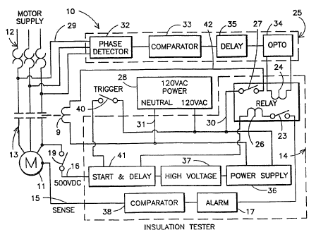
14 Referring to the drawings and to Figure 1, an
electric motor monitoring circuit 10 monitors an
16 electric motor 11 connected to a three phase electric
17 motor power source 12. A motor starter circuit 13 has
18 a motor starter coil 9 for activating the motor
19 starter. An insulation tester circuit 14 is connected
to the line 15 to the motor 11 and has a line 16
21 connected through a relay 19 to one of the motor power
22 lines 12. The relay 19 is a high voltage relay
23 actuated by a timing circuit, such as a 12 second
24 timer, during the insulation measurement to connect
the sense lead to the primary three-phase voltage.
26 The insulation monitor 14 is connected to an alarm 17
27 and includes a voltage relay 18 and a ground relay 20.
28 The output line 21 is connected to a relay circuit 22
29 having a first relay 23 actuated by the relay coil 24.
The relay coil 24 supplies electric current from the
31 phase monitor 25 to activate the relay which in turn
32 passes an electric current through the relay coil 26
33 to activate the relay 27 provided the insulation
34 monitor relay 20 is connected to allow the line 21 to
CA 02322791 2000-09-O1
WO 99/48194 PCf/US98/05359
6
1 connect to ground. The insulation monitor 14 is
2 supplied with power, such as 120 volt single phase AC
3 power from a power supply 28. The power supply
4 connects through a line 30 which passes through the
relay 27 when closed and forms a circuit through the
6 motor starter coil 9 and back to the neutral line 31.
7 The motor starter 13 is activated by the 120 volt AC
8 power supply 28 when the relay 27 is closed by the
9 flow of electric current through the circuit 21 to
actuate the coil 26 which occurs only when the relay
11 23 is closed as well as when the switches 18 and 20
12 are closed by the insulation monitor.
13 The control path of the motor starter coil 9
14 operates the motor start relay 13 by the insulation
monitor 18 to complete the control path through the
16 coil. However, both the phase monitor 25 and the
17 insulation monitor 14 are required to allow the motor
18 start relay 13 to be energized. The phase monitor
19 controls the activation of a relay 23 whose contacts
are in series with the coil of the insulation monitors
21 motor relay. If the contacts of the relay 23 are
22 closed, the required power is applied to the coil of
23 the motor start relay 13. The control path, however,
24 is not complete until the insulation monitor 14 has
determined that the motor has passed the insulation
26 test. When this occurs, another set of contacts 20
27 will close to provide a ground return for the coil and
28 allow the motor start relay to energize and the motor
29 will begin operation.
Turning to Figure 2, a more detailed block
31 diagram of the electric motor monitoring circuit in
32 accordance with the present invention is illustrated
33 having the electric motor monitoring circuit 10 having
34 the phase monitoring circuit 25 composed of four
CA 02322791 2000-09-O1
WO 99/48194 PCT/US98/05359
7
1 sections. The phase detector 25 is connected through
2 the conductors 29 to the three phase motor supply
3 lines 12 and are connected to the phase detector 32.
4 The phase detector detects and translates all normal
phase and phase error conditions from the motor supply
6 lines 12 into voltages that are evaluated in a
7 comparator circuit 33. The comparator section is a
8 window comparator circuit that compares the voltage
9 from the phase detector to two reference voltages, one
reference voltage is higher and the other is lower
11 than the phase detector voltage under normal phase
12 conditions. If phase errors occur, the voltage from
13 the phase detector will be above or below the
14 reference voltages and cause the OPTO section 34 to
deenergize. The OPTO section isolates the phase
16 monitor three phase power operation from the
17 insulation tester 14 voltage environment while
18 allowing the control signal from the phase monitor to
19 control a section of the insulation testers circuitry.
This deactivates the normally ON relay 24 that will
21 interrupt the voltage path of the insulation tester's
22 14 motor start relay coil 9. The reference voltages
23 create a range of voltages or window of operation that
24 the phase detector 32 voltage can vary about and still
not cause a phase error condition. Hysteresis is
26 provided so that there will be a dead zone between the
27 normal operation and the phase error conditions so
28 that small line variations will be canceled out.
29 A delay circuit 35 provides a time delay before
a phase error condition is declared. This is
31 primarily to avoid nuisance dropouts due to momentary
32 phase errors. An example of this type of phase error
33 would be when heavy machinery comes on line with
34 existing equipment to create a current surge on the
CA 02322791 2000-09-O1
WO 99/48194 PCTNS98/05359
8
1 three phase line. This condition will cause the live
2 voltage to sag momentarily and the phase detectors
3 voltage to drop below its lower reference voltage. As
4 a result, the phase monitor will deenergize the motor
starter 13 and stop the equipment operation. When the
6 line voltage rises to normal due an unloaded line, the
7 phase monitor l0 will attempt to energize the motor
8 starter but will shut down when the current surge
9 causes the line voltage to sag again. To avoid a
disaster, a time delay of less than 5 seconds before
11 the phase error condition is declared will allow heavy
12 machinery to come up to speed so that the line voltage
13 will rise and normal operation can begin. Reference
14 can be had to the three phase monitor circuit in the
Grant patent, No. 4,823,227, for a phase monitor
16 circuit.
17 The insulation monitor 14 has a transformer AC to
18 DC power supply 36 that provides a 12 volt DC to all
19 of the relays and to the integrated circuits. It also
provides a 5 volt DC source which acts as a reference
21 voltage and operates an oscillator circuit in the high
22 voltage section 37. The high voltage section 37
23 includes an oscillator driving the primary of a step-
24 up photoflash type transformer whose secondary is
rectified and filtered to approximately 500 volts DC
26 and 500 microamps. The insulation monitor is
27 basically a "force a voltage sense a current" type.
28 The 500 volt DC is applied to the motor windings and
29 any leakage current that is sensed will be evaluated
in the comparator 38. If the current sensed by the
31 sensing lines 15 develops a voltage higher than the
32 five volt DC reference of the comparator 38, the alarm
33 17 becomes active. When this condition occurs, a
34 double pole double throw alarm relay is energized.
CA 02322791 2000-09-O1
WO 99/48194 PCT/US98/05359
9
1 One set of the DPDT contacts activates a local remote
2 alarm. The other set of contacts interrupts the
3 voltage path to the motor start relay coil 9 so that
4 the motor cannot start. If the current sensed
develops a voltage that is below the five volt DC
6 reference, the motor start relay 14 will be activated
7 upon the completion of the insulation testing period.
8 The insulation leakage testing period starts when the
9 manual trigger 40 activates the start and delay
circuit 41. The trigger 40 can be actuated by a
11 mercury switch or the like positioned in a wet well by
12 the rising water level. The start and delay circuit
13 41 controls the relay that applies the 500 volt DC to
14 the line 16 to the motor windings and initiates a 15
second delay to allow the comparator circuit 38 to
16 evaluate the insulation resistance of the motor
17 windings. If the insulation leakage test is
18 successful, than the 500 volt DC is removed from the
19 line 16 and the motor windings and the motor start
relay 13 is allowed to energize. If the insulation
21 leakage test is not successful, the alarm section 17
22 will not allow the motor start relay 13 to energize.
23 An insulation testing circuit can be seen in our prior
24 U.S. patent, No. 4,716,487, to Horvath et aI. and
reference may be had to this patent for the operation
26 of the circuit.
27 Phase monitor circuit 25 derives its operating
28 voltage through the lines 31 and may, for instance, be
29 a 230 volt AC three phase power line while the
insulation tester 14 operates from a single phase 120
31 volt AC power supply 28. However, the phase error
32 indication of the phase monitor circuit requires the
33 insulation monitor 14 power supply 28 to be active for
34 a valid indication of the phase error so the single
CA 02322791 2000-09-O1
WO 99/48194 PCTNS98/05359
1 phase 120 volt AC power supply 28 is energized before
2 the three phase power supply 12 is energized. The
3 three phase monitor 25 must sense that the three phase
4 line voltage in the lines 12 or that there are no
5 phase errors before the insulation monitoring circuit
6 14 can be operated.
7 Once the insulation monitor has been triggered
8 with a manual trigger 40 and the motor windings have
9 passed the insulation test, the motor will energize
l0 and motor operation will commence. If a phase error
11 occurs in the startup sequence, a phase error
12 indication will flash and the insulation monitor will
13 not be able to perform its test even though the
14 trigger 40 to the insulation monitor has been
activated. If a phase error occurs while the motor 11
16 is running, the phase error indication will flash and
17 the motor starter 13 will drop out, causing the motor
18 operation to cease. Once the phase error is
19 corrected, the motor operation will start immediately
unless a delay in the delay circuit 35 is used.
21 The startup sequence for the circuit 10 involves
22 first applying a single phase 120 VAC power from the
23 power supply 28 to the motor starter relay coil 9 line
24 42, then measuring the three phase voltage from the
motor supply lines 12 with the phase monitor 10 and
26 adjusting the voltage on the phase monitor for the
27 measured value . A three phase line voltage is then
28 applied to the motor supply 12 through the lines 29 to
29 the phase monitor 10. If a phase error indication is
not indicated, the trigger 40 triggers the insulation
31 monitor 14 by applying 120 volt AC to the power supply
32 36 and to the start delay circuit 41. If the motor
33 passes the insulation monitor's test, the motor
34
CA 02322791 2000-09-O1
WO 99/48194 PCT/US98/05359
11
1 starter 13 will energize the motor 11 and motor
2 operation will commence.
3 It should be clear at this time that the electric
4 motor monitor for monitoring a circuit has been
provided which will deactivate the electric motor
6 before the machinery starts operating whenever the
7 monitoring circuit has detected an insulating leakage
8 of the electric motor windings of a predetermined
9 level and will deactivate the electric motor whenever
a three phase monitor circuit has detected incorrect
11 phasing or voltage. However, the present invention is
12 not to be considered as limited to the forms shown
13 which are to be considered illustrative rather than
14 restrictive.