Note: Descriptions are shown in the official language in which they were submitted.
CA 02322800 2002-06-14
-1-
FIELD OF THE INVENTION
The present invention relates to a color translating microscope employing
ultraviolet light in place of or in
addition to visible and/or infrared light sources. More specifically, the
present invention relates to a method and a
microscope which determine and represent differential absorption,
transmission, reflection, fluorescent and/or
Raman characteristics of a sample as a color image to a user.
BACKGROUND OF THE INVENTION
It has been desired for some time to find a low cost, reliable and yet
flexible means to view living and/or
dynamic processes at high resolution in real time. Another desire is to be
able to carry out 10 wide ranging
spectral imaging based on differential spectral absorption after such as,
Caspersson, T., 1940, Methods for the
determination of the absorption spectra of cell structures. Journal of the
Royal Microscopical Society. 60, 8-25, to
study biological samples without the addition of any contrast media. Yet
another desire is to substantially reduce
the amount of light that can potentially damage or affect the behaviour of a
sample. In other words, the desire has
been to view a sample with the slightest possible interference with its normal
behaviour in order to see its
operation in a state substantially the same as that which it would normally
experience in its usual environment.
Accordingly, it has been desired to eliminate stains, fluorochromes. dyes,
fixatives, preservatives or other additives
and to minimize external fields and radiations such as magnetic, electrical or
photon energy.
Color translating UV microscopes are known. In the past many inventors have
attempted to produce color
translating UV microscopes. For example, some prior art microscopes have used
photographic techniques as
described in: Barnard, J.E., 1919, The limitations of microsconv. Journal of
the Royal Microscopical Society, 39,
1-13; Martin, L.C., Johnson. 1928, B.K., UV Microscony, parts 1 & 2. Journal
of Scientific Instruments, 5, 337-
344 and 380-387: Lucas, F.F., 1930, The architecture of living-cells.
Proceedings of the National Academy of
Sciences, 16, 599-607: Barnard, J.E., 1939, Towards the smallest
living~thinQS, Journal of the Royal Microscopical
Society, 59, 1-10; Brumberg, E.M., 1946, A microscope for visual colour
microscopy in the ultraviolet ravs.
Comptes Rendus (Doklady) de fAcademie des Sciences de fURSS, 52:6, 499-502;
and Land. E.H., et al, 1949, A
colour translati~ UV microscope, Science, 109, 371-374.
Other prior art attempts at color translating UV microscopes have been made
using video techniques as
described in: Zworykin, V.K., Hatke, F.L., 1957, Ultraviolet television colour
translating microscope, Science,
126, 805-810; Zworykin, V.K., Berkley, C., 1962, Ultraviolet colour
translating television microsconv, Annals of
the New York Academy of Science, 97, 364-379; Caspersson, T., 1964, The
ultraviolet microscove, Journal of the
Royal Microscopical Society, 83, 67-68; and Caspersson, T., 1964, The studv of
living cells with the ultraviolet
microscope, Journal of the Royal Microscopical Society, 83, 95-96.
CA 02322800 2002-06-14
-2-
It is believed that all these prior art attempts failed due to the complex
nature of the solutions attempted,
the attendant costs and the high operating and maintenance burden and costs.
The results from these systems were
mediocre at best due to the delay in image availability in the photographic
processes and due to the low resolution
and long integration times of the video solutions available at the time the
work was carried out.
A more recent attempt at a useful UV microscope is shown in US Patent
5,481,A01 to Kita et al. As
shown in Figure 9 of this reference, a final image is produced from the
combination of a monochromatic UV
microscope image with a color visible light image to obtain a pseudo color
image. In other embodiments taught by
the reference, separate displays of the monochromatic UV image and the color
visible light image are provided to
the user. This reference suffers from disadvantages in that, for example, it
needs high power UV illumination to
provide sufficient illumination to the UV video camera which will be
detrimental to the sample, it does not
combine multiple three UV images from the same camera created with successive
selections of light of different
wavelength center and bandpass to create a full three colour visible image and
therefore it is prone to misalignment
of the individual cameras, and it is preset and not rapidly adjustable as to
the wavelengths of light chosen for
imaging, it does not use the extending resolving power of the deep UV range of
the spectrum in which cellular
absorption of biological specimens begins to offer the advantages of
absorption staining of living systems and it
will not resolve images at resolutions greater than those possible under
visible light viewing conditions, as the final
displayed visible light and monochromatic UV images are presented to the user
at the same pixel resolution.
It is desired to have a color translating UV microscope which provides
substantially real time image
presentation without damage to the sample and which ranges from the relatively
simple to construct and to use
simple version to the powerful and comprehensive imaging system in the
research version described herein.
SUMMARY OF THE INVENTION
It is an object of the present invention to provide a novel color translating
UV microscope which obviates
or mitigates at least one disadvantage of the prior art.
According to a first aspect of the present invention, there is provided a
microscope for translating spectral
information to a visible color image in which light from a source is separated
into components by either a set of
two or more filters or a device for providing wavelength limited light and
then passed through or reflected off the
sample and then imaged by an objective lens onto a video camera where it is
converted to visible light by a
fluorescent coating on the photosensitive surface of video camera which
provides the image as an electronic signal
which is then converted into electronic data by a video to computer interface
system and then recombined into a
multicolor image by computer processing finally creating a color visible image
on a display monitor where the
computer is supplied with infonmation on the position of the filters or
wavelength limited light in order to
synchronize acquisition of the images and the color translation and
recombination process.
CA 02322800 2000-09-08
WO 98/45744 PCT/CA98/00350
According to another aspect of the present invention, there is provided a
microscope for
translating spectral information to a visible color image in which light from
one or more sources is
separated into components by either a set of two or more filters or device for
providing wavelength
limited light and then passed through or reflected off an sample then imaged
onto the input of an image
intensifier by an objective lens then converted to visible light by the image
intensifier or other
wavelength translating device the output of which is then imaged on the input
of a video camera which
provides the image as an electronic signal which is then converted into
electronic data by a video to
computer interface system and then recombined into a multicolor image by
computer processing finally
creating a color visible image on a display monitor where the computer is
supplied with information on
the position of the filters or wavelength limited light in order to
synchronize acquisition of the images
and the color translation and recombination process.
According to yet another aspect of the present invention, there is provided a
microscope for
translating spectral infonnation to a visible color image in which ii~ht from
a source which emits
narrow spectral lines, as opposed to a continuum of spectra, is separated into
components after passing
I5 throu'~ii a sample and is then converted to visible polychromatic light by
a converter such as an image
intensifier and is then recombined into a multicolor image by a combining
images captured by a video
camera. video interface and computer where such images are synchronized with
the filter system.
According to yet another aspect of the present invention. there is provided an
optical
microscope system where an image intensifier and CCD camera combined with a
computerized image
capture and image processing system is used to convert images collected in
waveien=the outside the
normal range of human vision, such as soft x-ray. UV or IR, to visible images
and where, while at least
one of the images col lected is in the range 200 nanotneters to 300
manometers. some of the other images
used to produce the final color image can be collected in the range from 300
to 3300 manometers.
According to yet another aspect of the present invention. there is provided a
microscope which
includes active optical feedback for stabilization of the position and
intensity of the illuminating optical
system.
According to yet another aspect of the present invention, there is provided a
microscope which
includes active optical monitoring for recording and providing the data to
allow relating the effects of
the dosage of the illuminating radiation to the observed effects in the
samples and for modulation of that
illumination to prolong sample life.
According to yet another aspect of the present invention, there is provided a
microscope that is
capable of selecting between brightfield, darkfield, and reflected brightfeld
or reflected darkfield
illumination or phase contrast or other standard forms of illumination under
computer control.
According to yet another aspect of the present invention, there is provided a
microscope that is
capable of switching objective lenses under computer control.
According to yet another aspect of the present invention, there is provided a
microscope that is
capable of switching image intensifiers under computer control.
CA 02322800 2000-09-08
WO 98/45744 PCT/CA98/00350
-4-
According to yet another aspect of the present invention. there is provided a
microscope that is
capable of switching video cameras under computer control.
It is an object of yet another embodiment of the present invention to provide
a novel color
translating microscope which obviates or mitigates at least one of the
difficulties of the prior art. It is a
further object to provide a novel method of forming a color image of the
differential absorption of a
microscope sample.
According to yet another aspect of the present invention. there is provided a
microscope for
translating spectral information to a visible colour image in which light from
a source is separated into
components by a set of two or more filters then passed through an sample then
converted to visible
polychromatic light by a converter such as an image intensifier and then
recombined into a multicolour
image by a set of two or more filters where such filter sets are synchronized
with each other.
According to yet another aspect of the present invention. there is provided
a method of producing an ima';e representing the differential absorption of
fight by a sample.
comprising tire steps of:
(i) illuminating a sample with light of a first desired wavelengtlz by
imposing an illumination
t7lter between a multiwavelength light source and the sample ;
(ii) receiving light from the sample at a photon gain device which converts
the received light to
an intensified white light;
(iii} filtering said intensified white light with an image filter to obtain
visible light at preselected
wavelength for said desired wavelength;
(iv) forming an image of said tittered intensified white light: and
(v)'synchronously changing said illumination filter and said image filter and
repeating steps (i)
through ( iv) to illuminate said sample with light of a second desired
wavelength and to form an image
from visible light obtained from said intensified white light at a second
preselected waveleny~th for said
2s second desired wavelength.
BRIEF DESCRIPTION OF THE DRAWINGS
Preferred embodiments of the present invention will now be described. by way
of example
only, with reference to the attached Figures, wherein:
Figure 1 shows a color translating UV microscope in accordance with an
embodiment ofthe
present invention;
Figure 2 shows a color translating UV microscope in accordance with another
embodiment of
the present invention;
Figure 3 shows an embodiment of a microscope stage for use with a color
translatins UV
microscope in accordance with the present invention;
Figure ~ shows a color translating UV microscope in accordance with another
embodiment of
the present invention;
Figure 5 shows a color translating UV microscope in accordance with another
embodiment of
CA 02322800 2000-09-08
WO 98/45744 PCT/CA98/00350
the present invention;
-S-
Figure 6 shows a color translating UV microscope in accordance with another
embodiment of
the present invention;
Figure 7 shows a color translating UV microscope in accordance with another
embodiment of
the present invention;
Figure 8 shows a color translating UV microscope in accordance with another
embodiment of
the present invention; and
Figure 9 shows a block diagram of the control and electronic functions of a
color translating
UV microscope in accordance with an embodiment of the present invention.
Figure i0 shows a cross-sectional view of a microscope in accordance with an
embodiment of
tl3e present invention;
Figure 1 1 shows a graph of a typical UV illumination tiller spectra;
Figure 12 shows a graph of a typical visible li~~iit imagine filter spectra:
Figure 13 shows a three-filter filter wheel which can be employed with the
microscope of
Figure 2, 7, and f 0; and
Figure 14 shows a four-filter filter wheel which can also be employed with the
microscope of
Figure 2, 7, and 10.
DETAILED DESCRIPTION OF THE INVENTION
This invention stems from the desire to provide a powerful new research and
clinical tool which
advances the state of the art in microscopes for living or dynamic sample
microscopy while maintaining
the sample in a state as close as possible to it's normal conditions. In the
discussion below, the
following abbreviations are employed with these definitions: UV - fight from
the spectral region of
wavelengths shorter tl3an four hundred manometers; visible - light from the
spectral region from four
hundred to seven hundred manometers: IR - light from infrared, the spectral
region of wavelengths
longer than seven hundred manometers; NIR - light from near infrared, the
spectral region from seven
hundred to three thousand three hundred manometers; and a subset of IR and DIC
- differential
interference contrast, a means of enhancing image contrast in microscopy. The
terms sample denotes
the particular thing being imaged by the microscope and normally placed on a
slide in a stage or holder
in the microscope, it is sometimes referred to in the literature as the
object.
Generally, it is desired to carry out wide ranging spectral imaging based on
differential spectral
absotptions after the work of Caspersson, mentioned above, in order to study
biological samples
without the addition of any contrast media. It is also desired to follaw the
movement of highly active or
dynamic samples as they move in three dimensional space without a requirement
for manual control so
that an operator can find a sample component of interest and return some time
later and observe where
that component has moved to. It is also desired to substantially reduce the
amount of light andlor other
fields or energy sources that might damage or affect the behavior of a sample.
In other words, it is
desired to view the sample with the slightest possible interference with its
normal behavior in order to
CA 02322800 2000-09-08
WO 98/45744 PCT/CA98/00350
-6-
see its operation in a state substantially the same as that which it would
normally experience in its usual
environment. To this end, the use of stains, fluorochromes, dyes, fixatives,
preservatives or other
additives is desirably eliminated and the external fields and radiations such
as magnetic, electrical,
acoustic or photon energy to which the specimen is subjected are reduced.
Also, it is desired that the
system be relatively easy to set up, use and maintain, while being affordable.
Throughout this patent the microscope along with the related system components
are
collectively referred to as the UVM. This system will also excel in many other
fields of microscopy
such as metalfographic, crystallographic, forensic and chemical microscopy due
to the common
requirements of those field with the field of living microscopy in that
chemical spectrophotometric and
optical information is important to better characterize and understand the
sample. This new microscope
system can provide high light microscope resolution, real time high speed
image formation for stopping
fast action, non-invasive spectral absorption image contrast formation,
optical sectioning for three
dimensional analysis, and high speed tracking of moving samples or components
of samples in three
space.
I 5 This system employs one or more supervisory and image processing computers
which control
all the selections, operating levels and wavelengths and modes of the various
components of the UVM,
and process the image data collected and assemble it into a final image
according to a set of operator
selected algorithms. and feedback systems from the image data to the control
drives of the UVM
components to optimize image formation and track living or dynamic samples
over time. Without the
integration of image processing and machine control made possible by current
computer technology the
sophisticated ability of this UVM to form composite images and track living or
dynamic samples would
not be possible.
This system can produce unique images by rapidly cycling not only the
wavelength, bandwidth,
polarity and intensity of the illuminating light but also the method of
illumination between transmitted
brightfield, transmitted darkfield, reflected brightfield, reflected
darkfield, phase contrast, and slit
ultramicroscopic, as well as being able to rapidly change the polarity and
spectral bandwidth. by using
filtering or monochromators, of the light emitted from the sample, and change
the gain of the image
intensifiers to suit the intensity of the resulting light from the sample.
These rapid switching functions
of the light influencing components is then coupled with the computer's
capability to mathematically
process the images and carry out numerical operations to add, subtract,
multiply, divide or take other
mathematical or Boolean functions of the data to create the three color output
planes seen as red, green
and blue on the video display monitor.
An example of the unique capability of this system is the creation of a final
image in which
structural information obtained in the mid UVC spectrum is shown in blue while
fluorescent
information excited in the two hundred and fifty manometer range and emitted
in the blue visible
spectrum is shown as green and fluorescent information excited in the three
hundred and sixty five
manometer range and emitted in the red visible spectrum is subtracted from the
green image and the blue
CA 02322800 2000-09-08
WO 98/45744 PCT/CA98100350
image and the result is shown as red. The rapidity of the moving light and
light path selecting
components of the UVM can be fast enough to produce a full color translated
image of a moving
. sample in real time. This requires ninety image planes per second for a
thirty frame per second final
color image. The image processor must be able to handle mathematical
operations on ninety frames per
s second. output the result of these operations to a video display, and be
able to send data to the
supervisor computer at the same time. It also requires that the supervising
computer be able to direct
and accept position feedback from typically nine hundred motion commands per
second and four
hundred and fifty position feedback signals per second as well as deriving
focus, tracking. sectioning
and brightness control information from the image processor. Compromises in
the speed of the image
intensifier. the video camera. the video processor or the computer systems
will result in lower frame
rates for the final image.
The high resolution in this system is provided by the short working
wavelengths of the
microscope proper. This microscope system is designed to work in the UV, and
in some cases the
vacuum ultraviolet (VUV), spectral reunion while, if desired. maintaining
functional capabilities in the
! l visible and IR spectral regions. Since the resolution of a light
microscope is proportion to the
wavelength of light employed in image formation the use of UV and VUV light
results in
improvements in resolution many times the resolution possible with visible
light microscopy. it is
contemplated that this increase in illumination wavelength can result in the
microscope being able to
resolve features potentially as small as fifty nanometers.
The spectral range of the UVM, which can vary from a relatively narrow ran=a
in the UVC, to a
verv broad range encompassing the VUV, UV, visible and IR portions of the
spectrum. which, when
coupled with the dynamic selectability of spectral region, is important since
it forms the contrast of the
Image by employing the technique of differential absorption contrast. Since
different components of a
sample will absorb, transmit. reflect. scatter and emit li~zht at wavelengths
that are characteristic of it's
physical and chemical properties a microscope that can take full advantage of
these characteristics can
form images based on these differences where such differences are converted to
color images where the
colors of the final image correspond to the differential absorption,
transmission. reflection or emission
of the sample components. This type of contrast results in highly
differentiated images without the
requirement for the addition of any contrast media to the sample.
The real time image formation is provided by a video processor whit onboard
image processing
and data routing capability. The video processor imports the image from the
camera of the UVM. It
then processes the image according to one of several algorithms chosen by the
operator and finally
outputs the image to a video monitor and, or stores the data on a storage
media for future processing or
retrieval. The real time nature of the image formation is important to allow
living and dynamic
processes to be followed in real time or in slow motion playback. The real
time image formation
requires very fast spectral source scanning capability so that sequential
wavelengths of light can be
employed to illuminate the sample allowing the collection of image planes
corresponding to the
CA 02322800 2002-06-14
_g_
illuminating wavelengths, which are then overlaid to produce the final image
frame. In this way at least one, and
as many as ten or more, image planes are processed to create each image frame.
In the case of three images planes
per frame, the light source and intervening optics must be able to switch
illumination or mode three times in each
of the thirty cycles per second in a standard video frame rate to produce a
real time video output. Alternatively the
microscope can be operated in monochromatic mode to maximize the number of
frames available per second
allowing the microscope to image the motion of fast action or rapid dynamic
changes. This rapid imagining can
then replayed at slower frame rates to study the processes involved.
The living or dynamic sample commonly moves in three dimensions. These
movements result in the
sample moving out of the field of view and/or out of the focused plane of
view. In order to follow the sample the
microscope can track under computer control in both the X and Y directions of
the XY plane, and the Z direction
of the sample thickness. This requires either a stage system to hold the
sample which can move with the same
speed and repeatability as the sample in all three X, Y and Z directions or a
dynamic positioning system for the
optics so that they move relative to the sample. If three dimensional
information on the sample is required then the
computer can acquire images from a series of Z planes above and below the
current plane of focus by rapidly
scanning and acquiring images at intervals in the Z travel. These sections can
then be reassembled into a three
dimensional image by the computer image processingsystem. The UVM, when
operated at high magnifications in
the deep UV with high NA (numerical aperture, this is the numerical aperture
of the objective lens) objectives, has
a shallow depth of field which supports the creation of three dimensional
images.
In order to make the UVM simple to operate, all of the control tasks of the
various components must be
under the direction of, and optimized by, the computer. Initially, the
computer must establish an initial in-focus
image according to a user defined standard set of observing conditions. From
this point users can depart to
discover images that suite their applications. Advanced users must be able to
customize the as many of the
operational parameters of the UVM as possible in order to optimize the control
functions and methods used to
provide the images they seek.
A detailed set of descriptions of the basic and optional components employed
in typical versiosn fo the
UVM follows.
The light source 20 provides the required wavelengths of UV, and in some
cases, VUV, visible or infrared
light, to the microscope for sample illumination. The light source 20 can be
any source of photons of the required
wavelengths as will be apparent to those of skill in the art. The required
wavelengths are determined by the
differential absorption and other optical characteristics of the sample being
examined in the microscope. Light
source 20 is shown in figure 1 as a xenon sealed beam are source of the type
made by ILC Corporation, CA, USA.
In figure 2 and later figures the light source 20 is shown as a quartz halogen
compact reflector source such as the
OSRAM 64614TM, made by OSRAM Corporation, Montgomery, NY, USA.
Preferred light sources 20 for biological applications are sources which have
strong UV
CA 02322800 2000-09-08
WO 98/45744 PCT/CA98/00350
_9_
emissions and visible emission with little or no infrared emission. Low
infrared emissions result in
relaxed requirements to filter the infrared from the desired light to prevent
heating of the sample. The
most suitable illumination choices are high power quartz halogen lamps, xenon
lamps, deuterium
lamps, spectral line sources such as metallic spark or capillary lamps, or low
pressure arc lamps such as
free argon arcs or low pressure mercury arcs with additives to produce several
spectral lines.
Chemical and crystal microscopy and some biochemical applications benefit from
the ability to
use NIR or IR energy to obtain a wider range of spectral absorption image
data. Visible and NIR
illumination can be supplied by quartz halogen, or regular tungsten or other
filament lamp sources. IR
illumination can be supplied by black body radiators or other IR sources.
The xenon lamp provides a good low cost solution since it has a broad
continuous spectrum
from two hundred manometers to twelve hundred manometers. There are many
strong emission lines in
the near infrared which may need to be filtered depending on the application.
by a pre-filter, from the
xenon light before passing through the wavelength selection system between the
lamp and the
condenser.
!5 The deuterium lamp is also a ~~ood choice since it has strong spectral
emission between two
hundred and three hundred manometers and a few narrow spectral lines in the
visible. Tlte deuterium arc
has very little emission in the infrared making the infrared pre-filter
unnecessary in many
circumstances. A deuterium Tamp combined with a quartz halogen lamp makes a
~~ood source of
illumination since it effectively covers the range from two hundred manometers
deep in the UVC to
2200 manometers in the NIR. In figure 2 the UVM is shown with both a principle
light source 20 and a
secondary light source 25 which is here shown as a deuterium arc.
Several manufacturers make multispectral line spark. glow or arc lamps for
calibration and
scientific purposes. These lamps produce narrow spectral lines based on the
filling vTas mixture and on
the material used in the electrodes of the lamp. Such lamps offer a simple low
cost alternative to the
broadband sources mentioned above, but the user is then forced to choose from
the range of available
spectral lines and can not choose intermediate lines for special uses.
In the UVM illumination from more than one source can be combined or selected
to produce a
single illuminating beam of light. The light from the first light source 20 is
focussed into a collimated
beam by tense 30 which must be capable of transmitting the wavelengths of
light that are generated by
source 20 and required for image formation in the UVM. In cases such as those
shown in figure 2
where a second light source is used the light from the second light source 25
is focussed into a
collimated beam by tense 3~ which must be capable of transmitting the
wavelengths of light that are
generated by source 20 and required for image formation in the UVM. A beam
splitter operating as a
beam combiner 40, here shown as a prism beam combiner, or a set of mirrors
coated with spectrally
selective interferences layers. or a set of automated, cycling or manually
operated steering mirrors, can
be used to direct the light from the sources into the final illuminating beam.
Alternately a cycling
mounting for the sources can be used to reposition the desired source in such
a way that it produces the
CA 02322800 2000-09-08
WO 98/45744 PCT/CA98100350
-10-
illuminating beam. A typical arrangement consists of a set of three sources.
the first one of which is a
quartz halogen source supplying the visible and UVA (ultraviolet A, fight from
the spectral region from
three hundred and fifteen to four hundred manometers) illumination. the second
source being a
deuterium arc that supplies the UVB (ultraviolet B, light from the spectral
region from two hundred and
ninety to three hundred and fifteen manometers), UVC (ultraviolet C, light
from the spectral region from
one hundred and ninety five to two hundred and ninety manometers) and some VUV
(vacuum ultraviolet
light from the spectral region of wavelengths shorter than one hundred amd
ninen~ five manometers)
illumination and a third tungsten filament lamp that provides the longer
wavelength NIR illumination.
The choice of source, the drive energy supplied to the source, and, where
desired. the precise alignment
and focussing of the source, can all be controlled by the supervising computer
t 00 via suitable
computer controlled power supplies and positioning electronics.
In order to minimize the energy impinging on the sample all of the energy in
the illuminating
beam which is not required for ima~~e formation should be removed. Typically
in UV and visible light
microscopy applications this energy consists ofNIR and IR energy which is
produced by most light
sources 20 or 25 and will be present im the illuminating beam. Energy can be
removed from the
illuminating by using hot mirrors to reflect the unwanted energy and transmit
the desired energy or cold
mirrors to reflect the desired energy and transmit the unwanted energy.
Alternately or additionally,
absorptive components such as filters or solution filled cells can be used to
remove unwanted energy by
absorption. The filter component to remove any unwanted energy from the
illuminating beam is shown
as 45.
One ofthe elements of the UVM is the wavelength selection system. The
illuminating light can
be selected by wavelength, band limit function (short pass, lone pass, notch
or bandpass or
combinations of these functions), iris and li~_ht path to produce the desired
image characteristics. For
transmitted light work, the wavelengths can be chosen according the absorption
characteristics of the
sample. By making suitable choices of wavelengths and bandwidths particular
elements of the sample
can be imaged according to their differential absorptions. For fluorescent
work the wavelengths can be
chosen to maximize the excitation of the satnpie, and thus maximize the
resulting fluorescence or
autofluorescence. For Raman work, the wavelengths can be selected to strongly
excite Raman re-
emissions. For reflected light work the illuminating beam is dynamically
redirected so that it
illuminates the sample through the objective lens either directly or through a
special epi-illumination
objective with a coaxial light path arranged around the lenses of the image
forming objective lenses.
The illuminating beam can also be directed into an ultramicroscopic
illumination scheme where the
beam is directed at the slide from an oblique angle or from a point in the
plane of the slide but outside
its physical extents. Several modes can be sequentially selected by the
computer control system so that
the final image is an overlay of images produced using fluorescent, Ramam.
transmitted, reflected or
other images in various wavelengths.
There are several ways to implement the wavelength selection system ~0. The
wavelength
CA 02322800 2000-09-08
WO 98/45744 PCT/CA98100350
-11-
selection can be made by a monochromator with a computer controlled wavelength
drive system in the
form of a stepping or servo motor. Another form of single monochromator can
employ a computer
controlled scanning or vibrating mirror to select the desired wavelength. A
third variation uses a linear
array of optoelectric shutters such as a series of Kerr cells or liquid
crystal light shutters to select the
desired wavelength. The actual dispersing component in the monochromator can
be a prism 56 in
figure 2, a grating 55 in figure I, or a combination of more than one grating
or grating and prism, or an
acousto-optical grating. The bandwidth of the monochromator can be controlled
by a variable slit, a
variable iris or a tilting mirror. The monochromator can be replaced or
augmented by a cycling set of
illumination filters where the filters can be bandpass, shortpass or longpass
filters constructed as
interference transmission or reflection filters, interferometers, wedge
interference filters, or sonically
colored glass filters. The illumination filters can rotate in a fitter wheel
as shown in figure two where
the illuminating filter wheel 380 is similar in construction to the
intermediate filter wheel 335 described
in detail later. Alternately the filters can vibrate in a cycling mechanism.
These filters can serve as
order sorting filters for the monochromator or can perform the entire task of
light filtration removing
I s the need for the monochromator.
Figure 2 shows another embodiment of the present invention wherein a rotating
filter wheel 380
is added between the source of the illuminating beam and tine condenser to
rapidly filter, to compensate
the intensity of, or to selectively reflect wavelengths of light prior to
reaching the condenser. In some
cases the use of the fitter wheel 380 can allow the removal of the
monochromator 50 and f Iter 45. The
?0 alter wheel is driven by drive motor 385 which can be an alternating
current synchronous motor or a
direct current motor or a servo motor or a stepper motor, any of which would
be under control of the
computer 100.
Light from the wavelen~ah selection system 50 is reflected by mirrors 60 and
65 to direct it
towards the condenser 75 and sample 80. Alternately in reflected light
applications the light may be
25 redirected by movable mirror 90 mounted on positioning shaft 1 15 and
reflected by mirror 95 into beam
combining prism assembly 105 which directs the illuminating beam into
objective I 10 and then onto
the sample 80. Mirrors 60 and 65 may be coated with interference filter
coatings which perform some
or ail of the light filtering operations especially in specialty purpose built
UVMs for clinical
applications where a standard set number of wavelengths of light are desired
for imaging. Using
30 mirrors 60 and 65 as the illuminating filters may remove some or all of the
need for filter 45 or
monochromator 50.
Polarizing means in the form of polarizing sheet film or of any of the
commonly available
polarizers which can transmit and effectively polarize the light in the
illuminating beam can be used in
either or both of the illuminating path between the source and the sample, or
in the path between the
35 objective and the image intensifier to give polarization and rotary
information on the optical rotary
power of the sample. A polarizer in the illuminating beam is shown as 70 or
can be incorporated as pan
of rotating filter assembly 380, and a poiarizer in the image beam can be
incorporated as part of fitter
CA 02322800 2003-04-07
WO 98/45744 PCT/CA98/00350
-12-
assemblies 85 or as part of rotating filter assembly 335. These polarizing
means can be fixed
or can be rotating or vibrating in one of the sample or intermediate filter
sets or they can be
rotating in their own filter sets synchronized with other filter sets. It may
be desirable to use
an analyzing polarizing component between the objective and the image
intensifier to resolve
the optical rotation or state of polarization of a sample. This analyzer can
be manually or
computer controlled. For IJV operation crystal polarizers with air spaced (as
opposed to
cemented) components consisting of calcite or crystal quartz can be effective.
A mirror system under computer control can be implemented to couple a laser
beam
into the illumination path between the monochromator and the filter wheel. The
mirror must
be mounted on a fast operating mechanism so that it can be coupled into the
path in
synchrony with the frame rate of the imaging system. Alternately a notch
rejection filter in
the illumination filter set can be used to eliminate the laser beam from the
illuminating beam
when it is not being used to form an image. The laser beam is particularly
useful to add
Raman or confocal information to the image and for tracking moving samples in
darkfield
illumination where only a small portion of the image is required to be
illuminated.
Once the illuminating beam passes out of the illumination filters or
monochromator, a
beam steering mirror can be used to send the beam or a transmitted or
reflected light
illuminationpath. The transmitted light path sends the light through the
condenser and
through the sample to the objective, or in the case of darkfield the light is
directed through a
coaxial darkfield condenser or a standard darkfield condenser, while the
reflected path sends
the light through the objective, or through a coaxial illumination system
arranged around the
objective in the case of reflected darkfield. A presently preferred UV and
visible light
capable coaxial brightfield and darkfield condenser is described in J.E.
Barnard's book
"Practical Photomicrography", Edward Arnold & Co., London, Third Edition,
1936, page
2S 302, fig. 113 and related text and the contents of this publication. A
presently preferred UV
darkfield only condenser is described on page 303, fig. 114 of the same
publication. The
condenser 75 can be positioned for centration in the X-Y plane and for focus
in the Z
direction manually or by a system of three single axis drives or by a
combination drive
system, shown as 72 in figure 1, under computer control. This drive (or
drives) can be an
34 electric, hydraulic, pneumatic, piezoelectric or any combination of these
positioning systems.
The hydraulic and pneumatic drives have the advantage of removing external
electric and
magnetic fields from the area of the sample and so removing any external
influences that
these fields may create. Alternatively the condenser 75 can be preadjusted for
centration and
alignment with the objective 110 and stage 130.
3S An aperture and a scanning system can be used to implement a flying spot
microscope by placing these components between the wavelength selection system
and the
condenser (in transmitted light applications), or the beamsplitter or mirror
(in reflected light
applications). The flying spot method of illumination can be used to reduce
the illumination
of the total sample by scanning the
CA 02322800 2000-09-08
WO 98/45744 PCTICA98J00350
-13-
illuminating beam. Another application is for selective microbeam irradiation
studies where it can be
used to study selectively the effects of a small beam of light of a given
wavelength and bandpass on the
sample. In this method the beam is scanned over the entire sample to produce a
pre-irradiation image
then the beam is scanned or parked on the part of the sample to be irradiated.
After the desired period
of irradiation has passed the scanner area is increased or shifted so that the
irradiated area can be
compared to the non-irradiated surroundings.
Figure 7 shows another embodiment of the present invention which is similar to
that shown in
Figure 2 except wherein an aperture 555 and a scanning system 560 have been
added in the illuminating
beam path to scan the illuminating beam over the sample area under control of
the computer 100. The
scanning system can use a UV or muitispectral laser source 570 instead of the
monochromator 50 and
related filters 45 and light sources 20. The multispectral laser source 570
would contain at least one
wavelength in the UV for differential absorption imaging. The scanner can be
any of the commonly
available rotary mirror, galvanometer based mirror, solid state micromirror or
vibrating mirror types,
under the control of the supervising computer.
The sample 80 is commonly mounted on a slide 120 and covered with a cover
glass 125 and, as
such, it is readily adaptable to oil immersion techniques. Alternatively, and
depending on the particular
application, the sample may be mounted directly on the stage of the UVM as in
metalio~raphy or may
be used in an uncovered form such as direct immersion microscopy or may be
living samples on a slide,
well slide. or petri dish. The slide 120 or other support for the sample is in
turn supported by the stage
130 of the microscope.
The stage 130 employed with this microscope can be a conventional stage
however. for the
very high resolution which this system is capable of. the stage should be of a
computer controlled
nanopositionin; type. The stare can be moved in the X-Y directions under the
control of the computer
100 to accomplish positioning of the sample and to facilitate tracking of
moving samples in the sample.
In the tracking mode the computer 100 analyses the image and based on the
analysis, locks on to the
target component of the sample which it is desired to track and issues
positioning commands to the X-Y
stage drives 135 to keep the target area of the sample 80 within the field of
view and preferably
centered in the field.
The stage 130. or alternately the objective 1 10, is also controlled by the
computer 100 with
regard to its Z position. The Z position controls the focus of the system. The
Z position can also be
used for optical sectioning of the sample to provide information to the
computer 100 that it can then use
to reconstruct a three dimensional image. When high NA objectives 110 are used
in the UVM, very
thin optical planes can be imaged. Past experiments indicate that sections as
thin as 0.1 micron or
thinner are achievable. If; for instance five optical sections are collected
above and five sections below
the perceived center height of a spherical sample then the computer I 00 can
recreate the contours of the
sphere in three dimensions for display on the computer monitor by processing
and reassembling these
sections into a final image. Components within the sample can move in the Z
direction as well as the X
CA 02322800 2000-09-08
WO 98/45744 PCT/CA98100350
- 14-
and Y direction during tracking so the Z stage positioning system can also be
interfaced to the X and Y
tracking drives from the computer so that it follows the sample movement in
all three directions. While
long term tracking of the sample is taking place the computer can switch the
illumination to a
wavelength, bandwidth, intensity and duty cycle which minimizes the effect of
the illumination on the
sample by controlling the illuminating filter wheel 380 or the monochromator
50 or the source 20, and
25 if employed, intensity. The computer can also take images at intervals
under full illumination
conditions to give a time lapse indication of what has occurred in the sample.
A stage position feedback system is also shown in figure 2 and in more detail
in figure 3 where
a capacitive probe 230 is coupled capacitively to the stage 130. The probe 230
is isolated from the
!0 microscope frame by insulating section 220 mounted on support 210. Fi;ure 3
shows an enlarged view
of an embodiment of the sample part of a UVM in accordance with an embodiment
of the present
invention. The sample 80 is mounted on a slide 120 and covered with a cover
glass 125. The slide is
supported by tire stage i30 which can be moved in three dimensions by the
positioning drive 135 under
computer 100 control. Spatial scanning is accomplished by X and Y movements of
the stage.
I 5 Focussing and optical sectioning for three dimensional reconstructions are
provided by Z direction
movements of the stage. The condenser 75 is mounted on a supportin~~ rin~~ 76
which is positioned in
three dimensions by drive system 72 under manual or computer 100 control. The
distance between the
objective 1 10 and the stage [and hence the top surface of the cover blass in
slides or samples where the
distance from the stage to the top surface of the cover glass is accurately
controlled or known] is
20 monitored by the capacitive probe system where the capacitive prove 230 is
capacitively coupled to the
stage l30 to provide distance information based on the capacitance of the gap
between the flat surface
of the probe and the stage. When this system is used with slides systems of
known and accurately
controlled thicknesses then the capacitive probe 230 provides a feedback
sip=nal to computer 100 to
allow automatic focusing.
?$ It is presently believed to be advantageous for the design to take into
account sources of
external magnetic and electrical fields passing through the sample and
eliminate or minimize them.
This can be accomplished by electrostatic shielding of the sample area. A
magnetic path can be
introduced around the sample area to minimize any magnetic field in the sample
area. The magnetic
shielding can be accomplished with specialty magnetic alloys, such as mu
metals. or alloys containing
30 iron, alternately ferrite layers can be employed in the inner tubular
housing design. The minimization
of these fields helps to ensure that the sample is not being influenced by
external factors which might
give a misleading impression of the sample's normal function in its usual
environment. Electric fields,
magnetic fields, light levels and wavelength. acoustic fields, temperature and
pressure at the sample
must al( be taken into account when considering whether or not the sample is
experiencing conditions
35 similar to those it would normally find in vivo. The stage in an automated
microscope can produce
intense magnetic fields from drive motor components, intense electric fields
from piezoelectric drives
and acoustic fields from the same source since any alternating current
component in the piezoelectric
CA 02322800 2000-09-08
WO 98/45744 PCT/CA98/00350
-15-
drive voltage will be converted into a displacement with a resulting acoustic
component. For the very
high magnifications and resolving power that the UVM makes possible it becomes
more important to
eliminate the sources of external fields since they can act to displace or
vibrate components of the
imaging optics or of a living sample thereby affecting image quality.
To take full advantage of the increases in resolution offered by the short
wavelengths of the UV
light employed it is desired to provide a very stable supporting system so
that there are no vibrations or
other motions of the sample relative to the image forming optics, image
intensifier and video camera.
The resolution of a UV microscope with a I .3 NA objective operating at two
hundred and fifri~
manometers will be in the order of one hundred and twenty manometers. Tlfe
UVVI can employ standard
C shaped microscope frames and can be retrofitted to existing microscopes by
changing the required
optical components. While the UVM can be constructed on a standard microscope
C shaped frame. it is
~~eneraliy not preferred. as the UVM will suffer from degradation of the image
due to vibration. which
is also true if the UVM is retrofitted into an existing C frame microscope.
For the best image
performance it is desired to provide a support with as little vibration as
possible. For this reason past
attempts at UV microscopes desi~lned for the best possible resolution have
taken ?reat pains to isolate
the image forming components from vibration and have typically been
constructed using a massive
three point mounted optical bench with or with out passive or active vibration
isolation. This style of
construction typically resulted in a large and costly form of design. The
presently preferred design for
the present invention is to use a very rigid and vibration damped tubular
housing I.~O which transmits
vibration equally to all the image forming components and the sample. In this
way the whole unit can
be subject to vibration but the vibration will be substantially identical in
amplitude. and phase for ail of
the critical image forming components.
Since some versions of the UVM design require tile use of a rotary or
oscillating filter drive or
drives, it is preferred to mount the drive outside and mot in direct contact
with the tubular frame of the
imaging components of the microscope. In such a design the drive components
are mounted in a
second outer tube which also supports the inner tube on vibration damping
mounts. The rotating filters
project into the inner imaging tubes through slots in the tube wall and do not
come into direct contact
with the inner tube at any point. The outer tube also serves as a light and
dust tight housing to keep
stray light and dust from contaminating the image or the components in the
imaging tube.
The UVM can use a single fixed objective lens 1 10 or it can use a rotary
nosepiece containing
more than one lens. The nosepiece can be under manual or computer 100 control.
Alternately it can use
a slider on a circular path to switch between two or more lenses. The
objective lens 110 or tenses used
in the UVM must be capable of transmitting the wavelengths of light employed
iii the system.
Reflective, refractive or combination objectives can be used. Lens materials
include quartz, calcium
fluoride, lithium fluoride, sapphire. or spinet or any other suitable glass or
crystalline materials. In
order to take full advantage of the higher resolving power of the UV ligl3t
the most applicable objectives
wilt generally be the high power immersion lenses. Keeping the NA of the
objective lens high is also
CA 02322800 2000-09-08
WO 98/45744 PCTICA98/00350
- I6-
important due to the effect of NA on the resolving power and the depth of
field of the system. Optical
sectioning for three dimensional image formation requires the shallowest depth
of field possible. For
applications which do not require anything but visible and UVA operation tills
system can use
conventional glass lenses which have been tested and selected for UVA use.
Figure 8 shows an embodiment of the present invention which is similar to that
shown in Figure
1 except that a system of mirrors and a beamsplitter have been added to allow
the illumination path to
be switched from transmitted to reflected light under computer control. The
mirror 90 can be moved
into position to intercept the illuminating beam by actuating shaft 115 which
can be controlled by a
cam, motor. solenoid, hydraulic or air actuator controlled by the computer I
00. When the mirror 90 is
in the reflecting position. the illuminating beam is directed via mirror 9~ to
the beamspiitter 105 acting
as a beam combiner which directs the illuminating light down through the
objective 1 10 to accomplish
reflected light microscopy. The mirror 90 is arranged to be driven so that it
can be cycled into the beam
path many times per second, or alternately the mirror 90 can be arranged on a
rotating wheel arranged
as a light directing chopper wheel.
Vacuum UV capability can be added to the UVM by adding suitable li~~ht sources
20 or
secondary light sources 25 such as metallic spark sources. along with suitable
optics. The microscope
must be able to convey the VUV illumination and image information to the image
intensifier which can
be accomplished by purging all the fight paths between the source and the
sample, and between the
sample and the ima~~e intensifier, with dry nitrogen or other gases which do
not absorb in the VUV
region of interest. This is necessary since the oxygen in the air strongly
absorbs UV light below about
one hundred and ninety seven manometers. The lenses in a VUV version of the
UVM must be
constructed using reflective objectives and optics or they must use refractive
materials that transmit at
the wavelengths desired. Retlective optics Izave been the optics of choice for
VUV use since they
exhibit no chromatic aberration and can perform equally well over a very wide
spectral range. Typical
choices for VUV refractive system optical components are lithium fluoride.
calcium fluoride and
sapphire. A VUV version of the UVM operating with an objective of an NA of 1.4
at one hundred and
twenty five manometers will be able to resolve samples fifty five manometers
in diameter or less.
The use of this system in scanning mode in much the same way as a confocal
microscope with
a small point of light will increase this resolution further. The computer can
electronically remove all
the image information except the single pixel corresponding to the scanning
position of the point of
light to achieve performance exceeding that of a traditional confocal
microscope. This version of the
UVM which uses very short wavelengths with their attendent reflective optics
and special transmissive
components can. when coupled to the differential absorption capabilities of
the microscope in this
wavelength range, produce the highest possible resolution and image quality
achievable with a "light"
microscope. Further gains in resolution and consequently magnification are
possible by using soft X-
ray sources and optics. In the VUV version of the UVM the slide must be
coupled to the condenser
with a suitable VUV transmitting fluid and the coverglass must be coupled to
the objective with the
CA 02322800 2002-06-14
-17-
same fluid. The sample must also be mounted in a fluid or mountant which is
transparent to VUV of the desired
wavelengths. A discussion of vacuum UV optics for microscopy and a review of
the subject is found in
"Microscopy in the region of wavelength 2,000 to 1,000 angstroms", B.K.
Johnson, (1953), 73:24-29, Journal of
the Royal Microscopical Society, London.
After the light from the sample is collected by the objective lens 110 an
intermediate filter set 85 can be
used to isolate components of the light transmitted by, or originating from,
the sample. It is common for biological
materials to exhibit broadband blue autofluoresence when illuminated by a
short wave UV light source 20. This
autofluorescence can be strong enough to fog the desired UV image. It is
therefore important to remove the blue
autofluorescence from the image prior to it encountering the image intensifier
160. The UV image can be isolated
from the autofluorescent image by employing a UV transmitting and visible
absorbing or reflecting filter between
the objective and the image intensifier. As mentioned above this filter set 85
can incorporate polarizing
components or it can be desired to mount an analyzing polarizes under computer
100 control and separate from the
filter set. Alternately any of the intermediate filters or polarizing
components can be mounted in a rotating filter
set. Such a rotating filter set is shown as 335 in figure 2 where the outer
light tight housing contains an inner
rotating filter holding wheel 340 with several filters 85 mounted in it. The
light from the objective 110 passes
through a second rotating filter wheel which is substantially the same as the
filter wheel described earlier in this
paragraph. The filter wheel is driven by motor 345 which can be any of the
motor types described above which
can be controlled by computer 100 or can be manually selected.
Alternatively, it may be desirable to study the fluorescent or autofluorescent
components of the light
emitted by the sample due to internal chemical components of the sample or due
to fluorochromes added to the
sample. This is done with filters which transmit the wavelengths of the
fluorescence or autofluorescence and
block the exciting UV wavelengths. It is also possible to employ narrow band
notch rejection filters to observe the
Raman re-emission wavelengths from the sample. In Raman microscopy a high
power monochromatic,
polychromatic or narrow band source, such as a laser or filtered lamp, is used
to excite the sample which then re-
emits lights at other wavelengths determined by the chemical and physical
characteristics of the sample. Then a
Raman notch filter 85 situated in the image path between the objective and the
image intensifier attenuates the
narrow band exciting wavelength in order to allow the Raman emissions to be
viewed at wavelengths other than
the exciting wavelength.
In an infinity corrected version of the UVM the next component in the optical
system is a tube lens 150 to
convert the infinity focussed image to a fixed focal point image on the input
screen of the image intensifier 160 or
video camera 170 in cases where an image intensifier is not used and the image
is focused directly onto the
sensitive surface of the video camera 170 by the tube lens 150. It may be
desirable to control the exact position of
the tube tense 150 and consequently the focus of the image on the input screen
of the image intensifier 160. In
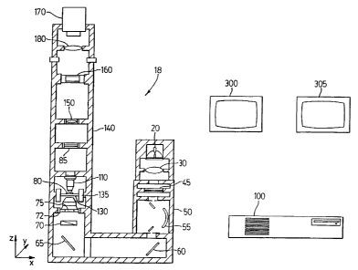
order to accomplish this a Z positioning drive 350 can
CA 02322800 2000-09-08
WO 98/45744 PCT/CA98/00350
-I8-
be used to move a mount 325 holding the tube tense 150. The tube lens 1~0 is
moved to control the
focus of the image on the input screen of the image intensifier by Z
positioning drive 350. The process
of focussing the video camera on the output screen of the image intensifier is
assisted by projecting an
alignment pattern from target 360 illuminated by light emitting diodes located
at 370 and shining on
target 360 onto the input screen of the image intensifier. The pattern is
imaged with lens 330 via mirror
315 which is moved into position on the optical axis by positioning drive 310
and 320 under computer
100 control. The image is reflected on to the image intensifier by movable
mirror 315 which is located
on the end of the movable shaft 310 which is positioned by drive 320.
If an image intensifier 160 is used. it fulfills two functions in this
invention. Firstly, it converts
any light within the spectral sensitivity range of the plzotocathode to light
of spectra determined by the
phosphor used on the output screen, this conversion is typically used to
convert UV, VUV or IR light
into visible light. Secondly, it provides photon gain between its input and
output allowing much less
light to be used to form the image of the sample, this means that the sample
is exposed to much less
light than in a normal light or UV microscope. This is particularly important
in UV microscopy since
IS UV light in the regions below three hundred and ei~~htymanometers can have
strongly detrimental
effects on living samples. The use of the image intensifier tube reduces this
exposure to values
typically 1/10,000 of the intensity normally required to form an image. The
image intensifier can be a
proximity focussed diode design or a single or double microchannel plate
design or any other type of
image intensifier. The double microchannel plate image intensifier offers the
highest photon gain but at
the expense of resolution and signal to noise ratio. The double microchannel
plate type, operating at the
highest possible voltage, is chosen when greatest light gain and consequentlv_
the least possible
interference with the normal activities of a biological sample is desired.
The choice of an appropriate input photocathode for the image intensifier 160
is important to
the efficient operation of the UVM since different photocathode materials
exhibit widely varying
?5 spectral sensitivities. Phosphors are available in a wide variety of
emission wavelengths and emission
efficiencies. In order to accomplish the highest efficiency in the transfer
from input light to output light
a high efficiency phosphor such as P20 must be used, in combination with a
photocathode optimized for
operation in the spectral region of primary interest. For instance, short wave
UV conversion requires a
photocathode that is sensitive in the deep UV such as the S20 photocathode.
Visible or extended red
operation, for fluorescent. autofluorescent or Raman imaging, requires the
addition of other sensitive
materials to the photocathode such as those used in the current multi-alkali
systems. Visible insensitive
image intensifiers, commonly described as solar blind, provide UV images
without the interference
from visible autofluorescence from the sample. In general a good choice of
photocathode is one which
exhibits wide spectral bandwidth and high sensitivity.
In some cases such as are illustrated in figures four and six, it may be
necessary to arrange for
more than one image intensifier to be positioned in the optical path to allow
for operation over a wide
spectral range. In figure four three image intensifiers 155. 160. and 157 are
provided with three
CA 02322800 2000-09-08
WO 98/45744 PCT/CA98/00350
- 19-
wavelength ranges of signal by dichroic beamspitters 235 and 250 and mirrors
260 and 240. The
resulting intensified image is directed to cameras 190, t 70 and 195.
Figure 4 shows a triple imaging system embodiment of the present invention. In
this case, three
image intensifiers 155, 160 and 157 and three video cameras 190, 170 and 195
with their related
filtering beam splitters 235 and 250, tube lenses 655. 660 and 665 and relay
lenses 670, 675 and 680
receive parts of the video spectral information. The benefet of this system is
high imaging speed. For
example where the video camera is capable of eighty frames per second this
configuration allows the
computer to assemble three image planes into a f nal color image eighty times
per second for a ftnal
frame rate of eighty frames per second instead of the [eighty divided by
three] frame rate for a single
camera using a series of sequential image planes as in the previous figures.
The multi spectral light in
the image from the objective 1 10 is divided into its spectral components by
beamsplitters 235 and 250
which may or may not contain dichroic coatings on the hypotenuse of the beam
splitter or interference
fitters on the external surfaces. The Light which goes straight through the
beam splitter reaches the
center system while the light reflected at the beam sputter is then reflected
throu~_h ninety degrees by
the mirrors 240 and 260 into the two outer systems. The mirrors 240 and 260
can be coated with
interference filters so that they are selectively reflecting for certain
wavelengths in which case they can
perform part of the filtering function. In this type of system it may be
necessary for the monochromator
to provide several wavelength regions simultaneously so that the required
three spectral ranges are
available to be separated.
As the output of the image intensifier is a phosphor screen, it represents a
lambertian source and
li~~ht from this screen must be transferred or relayed to the observer or
video camera. This relay can be
done with a relay lens l80 which has the disadvantage of low collection
efficiency. or it can be done
with a fiber optic relay bundle or taper shown in fi~_ure two as 270, commonly
known as a minifier,
which is able to collect a substantially increased amount of the light emitted
by the output phosphor
screen of the image intensitier 160 and directly convey it to the video camera
170.
~'ormaily the UVM would use a single CCD monochrome analog camera or a single
CCD
monochrome digital camera such as a DALSA CA-D4 which is a 1024 x 1024 pixel
design. Figure 5
shows another embodiment of the present invention. In this example, a UV
sensitive video camera such
as a lumigen or Unichrome coated CCD or a photodiode array camera or a
photodiode / CCD hybrid
camera or a tube camera 170 is used alone to form the image plane information.
In this case there is no
image intensifier required to carry out the spectral color translation from
UV, visible or NIR, to visible.
The disadvantage of this system is that the sample will receive an amount of
light that is greater than the
system which utilizes an image intensifier such that the increase in light
will be equal to the gain of the
image intensifier. Due to the increase in light, it is contemplated that this
type of UVM system is more
suitable for non-living applications such as metallography, semiconductor
imaging, crystallography,
microspectrophotometric imaging of fixed biological systems, light stable
and/or resistant samples.
Figure 6 shows a similar arrangement except the system does not employ image
intensifiers but
CA 02322800 2000-09-08
WO 98/45744 PCTICA98/00350
-20-
instead uses video cameras which are directly sensitive to the wavelength
ranges used for image
creation. Alignment and vibration can present real problems to the successful
accomplishment ofthis
type of arrangement and consequently the arrangement of figure two is
preferred. Alternately a sliding
circular track can be used to position one or more image intensifiers in the
optical path. In the case
where a sliding track positions the image intensifier it may be desirable to
put a relay lens in one
position of the sliding track to transfer visible and NIR image information
directly to the video camera
bypassing the image intensifier. Figure 6 shows another three camera
embodiment of the present
invention which is similar to that of Figure ~1, but without image
intensifiers as in Figure S. Here three
UV sensitive cameras i 70, 190 and l9~ are used to ~~enerate the image planes.
In the same wax as
l0 figure five above this system has reduced sensitivity but high frame rates
as in figure four. y
For direct viewing of the image intensifier output, it is possible to utilize
a standard microscope
binocular or trinocular after the image intensifier. If this direct viewing
system is implemented, a slider
can be used to hold the image intensifier or image intensitiers and exchan;e
the position of these items
with a compensating lens to directly send the image information to tile video
camera or to the trinocular
1 S or binocular. In such a system the microscope functions as a normal
microscope in the visible and
fluorescent modes of operation and can tJzen switch to UVM operation for non-
visible and image
intensitied work.
Depending on the type of final optical system employed it may be necessary to
effectively
block UV light from reaching the operators eyes through the binocular or
trinocular system. This can
20 be done with UV blocking filters such as Schott Glass WG-370 or similar
products. UV light can also
lead to fluorescence in the optical components of some objectives. condensers
or eyepieces. This is
another reason why optics for the UV microscope must be specially designed for
the best possible
image formation.
A second area of UV exposure concern is the sample and stage area,
illuminating light path and
25 source housings. All of these areas need effective blockin<, components to
ensure that UV liEht does
not leak into the working area outside the UVM. A UV interlock and guard can
be used to reduce or
eliminate the possibility of user e~cposure to the UV light at the sample area
of the microscope. The
guard consists of a UV opaque shield which prevents UV glare from reaching any
point where the ev_ es
of the microscopist or an observer could potentially be located.
Alternatively. or additionally, an
30 automatic shutter consisting of a UV opaque material in the illuminating
path can be used to remove
UV from the illuminating beam when the sample area guard or, in some versions
of the UVM the
sample holding chamber area, is open.
If a trinocular is provided for direct visual observation of the output of the
image intensifier,
where the image intensifier intercepts the image from the sample, any UV light
from the source can not
35 normally pass through to the observer from the sample so the eyepiece may
not have to filter all the UV
from the image. Careful analysis of all the spectral emission from the image
intensifier phosphor and
then to effective filtering of any unwanted wavelengths will greatly enhance
the contrast ratio and the
CA 02322800 2000-09-08
WO 98/45744 PCT/CA98/00350
-21 -
apparent focus of the final image. The eyepiece can be a monocular, binocular
or trinocular system
commonly used in light microscopes or any other viewing arrangement such as
would be obvious to
one skilled in the art of microscopy.
High speed and gated image intensifiers can be used for tracking or freezing
the motion of fast
moving samples. In this case it is important to choose the output phosphor of
the image intensifier with
due consideration to the required response speed of the phosphor. The decay
time of the phosphor must
be sufficiently short that the image from a previous image plane does not
persist into the time interval
for the following image plane. 1n order to provide stop motion effects for
freezing the motion of a
rapidly moving or oscillating sample either the image intensifier can be gated
at precise intervals by
external electronics, or the illuminating light path can be shuttered by a
controllable shutter. The
shuttering can also be used for dose reduction or selective wavelength
elimination or can be used for
dose reduction on the basis of the relative destructive effects of various
doses at various wavelength.
For example, the illuminating shutter can be opened only twice per second
during the least harmful
wavelength of a set of wavelengths making up a frame interval while the
microscope was being used for
t 5 searching and, once the desired sample is located, then the full range of
wavelengths is allowed to pass.
Alternatively, neutral density titters can be introduced into the illuminating
beam path during
searchin<~ or long term tracking of components to reduce the exposure of the
sample. The neutral
density trlter is chosen to provide an image only slightly above the
perception limit of the observer's eye
or above the noise floor of the CCD. Once a sample of interest is located the
filter is removed allowing
30 the image intensity to take more complete advantage of the available
dynamic range of the observer's
eye or the CCD. Neutral density filters which absorb the energy not
transmitted can become very hot so
they may need to be cooled. A reflective neutral density filter can be easier
to apply since it does not
absorb the heat. but the designer must attend to cooling the area where the
reflected energy ends up so
that this area does not overheat. Care must be taken if the energy is
reflected back into the source since
25 this reflected energy tnay overheat the lamp envelope resulting in sudden
and destructive failure of the
lamp.
It is possible to design a UVM without an image intensifier by using
photodiode or
photodiode/CCD hybrid cameras such as the J 024 x 1024 array camera designed
by EG&G Reticon, or
by using UV sensitive CCD arrays which have been coated with a UV phosphor
such as lumigen or
30 Unichrome. The disadvantage of a UVM without an image intensifier is that
the UV levels at the
samples must be much more intense which requires more powerful sources of UV
light, creating more
ozone in the lamp housing and greatly increasing the risk of potential damage
to the sample. Therefore,
it is presently contemplated that use of a UVM without an image intensifier is
a limited to short
duration work in the UVC or to working on fixed, inorganic or light stable
samples.
35 It is also possible to include more than one type of video system in the
UVM. For example, it
may be desirable to arrange fight paths or camera changing sliders that allow
UV image information to
be sent to an image intensifier and camera while visible image information is
sent to a color CCD
CA 02322800 2000-09-08
WO 98/45744 PCT/CA98/00350
-22-
camera, and NIR and IR image information is sent to a third IR array camera.
In this way the final
image formed by the computer system can cover an extraordinarily broad
spectral range.
As image intensifiers can be damaged by exposure to light sources due to high
photocurrent
while in operation. it is desirable to design a system to shut down the power
supply to the image
intensifier if the current demand increases beyond a preset level. Once the
tube is shut down, the
current limit can be reset or the operator can choose to override it for a
predetermined time period. The
current limit on the image intensifier can be realized by sensing the nanoamp
current consumption of
the image intensifier during normal operation using a resistor and operational
amplifier. The signal
from the current sensing system can then be used to shut down the power supply
for the image
intensifier, or the light source 20 or both.
The UVM can be constructed with integral liglzt feedback and dosimetry built
in to monitor and
stabilize the output of the source and integrate the exposure of selected
areas of the sample. The light
monitoring can be implemented through the video system or it can be
accomplished with separate
photodiodes using a small diverted portion of the illuminating light path
typically just before the light
I S enters the condenser. For advanced monitorine in living system work, it
may be desirable to use a
monochromator with a linear array detector to monitor not only the intensity
of the illuminating
wavelength but also the spectral characteristics. This monitoring version can
be useful in supplying the
feedback for synchronizing the video image capture with the illumination sv_
stem.
The image information from the video camera is captured using an image capture
board such as
the Matrox Pulsar or the Matrox Genesis depending on the speed and level of
capability desired for
final imaging. A simple video capture system can be used to transfer the image
information into digital
form in the main memory of the computer where the computer controls the UVM
and carries out the
processing and display generation of the image data. A more sophisticated
video processor such as the
Genesis can be used in which the video processor carries out the image
capture. data storage, data
handling, mathematical processing and display generation, leaving the computer
more time and
resources to handle UVM control and supervision of the image processing tasks.
Image processing includes overlay of several monochrome image planes to create
a final
multiplane color display. Typically color translation involves the conversion
of three monochrome
images from a non-visible region into the visible. The information in the
monochrome images is
overlaid to create the final color image with image planes displayed as red,
green and blue information.
As well as the image processor supplying overlay functions to form a full
color translated image the
processor also provides addition, subtraction, multiplication, logarithmic
operations, Boolean
operations, dark offset and noise cancellation, contrast expansion and target
tracking of image data.
The image processor can also, in some cases, supply vector information on the
movements of a sample
or sample component to the supervising computer to direct the position drives
of the UVM while
following motion in the sample.
The image produced by the UVM can be generated by a video adapter such as a
VGA or SVGA
CA 02322800 2002-06-14
-23-
adapter included as part of the video processor or as part of the main
computer. The final image is displayed on
video monitor 300 which may be any type of video or graphics display monitor.
While the control information can
be displayed on the same video monitor 300 and the user can toggle back and
forth between the image and the
control screens it is most helpful to have two seperate displays one for video
and one for control information so
that both can be viewed at once.
The use of a separate adapter on the video processor is most desirable since
then the first display 300
provides the final image while the second display 305 provides UVM control
information and settings screens
created using a program such as National Instruments Labview software to
implement the UVM's graphic control
panel.
The control system for the UVM consists of computer controlled power supplies
to control the sources
and the image intensifier; computer controlled positioning drives to control
filter and focus drives; tine positioning
drives to control the three dimensions of motion in the stage and condenser
positioning systems: and
environmental controls to keep the slide in the desired environmental
conditions.
Figure 9 shows the electronic signal path in one embodiment of the present
invention. The video
information is collected by video camera 170, and 190 and 195 if used, which
can be a digital or analog camera
consisting of a CCD array, a photodiode array, a tube camera or any other
electronic image producing device. The
image information is transferred to a video processor 580, 585, 595 and 590.
This video processor can be internal
to the computer in a form such as one or more of the Matrox Genesis video
processor card, a combination of
computer 100 processing and VGA or SVGA cards, or it can be an external sub-
system The video processor can
perform several functions: converting the input signal to a digital format in
processor section 580: performing
mathematical functions, including image plane overlay or combinations, to form
color images, addition.
Subtraction, dark offset or noise compensation, contrast enhancement, motion
detection: three dimensional
recreation from optical sections on the image data in a digital signal
processor 595; creating a digital output
display signal for driving a computer display monitor 300 in a display driver
section 585 which can be an SVGA,
RGB. NTSC, PAL, SECAM or other driver; and handling transfer of all or
selected portions of the image data or
control data to the computer 100 via section 590. The final image is displayed
on display monitor 300 and the
control information for the computer is displayed on display monitor 305.
Alternately both the image and the
computer control information can be alternately displayed on a single monitor
300 and selected under user control.
Figure 9 also shows how the computer controls the various positions and modes
of operation of the
embodiment of the UVM depicted in Figure 1. The control systems for the other
embodiments described in this
patent typically require more channels of control for the additional
controllable components. The UVM is
controlled via inpuboutput drive controller 760 which both directs the control
function and receives feedback from
the movable component to indicate its current status. The intensity of the
light source 20 and secondary light
source 25 can be controlled via their power supplies
CA 02322800 2002-06-14
-24-
800, the monochromator center wavelength can be controlled by its drive system
805, the monochromator 50
bandwidth can be controlled by its drive system 810. The condenser 75 is
controlled for X, Y and Z position by
drive system 72 which is controlled by drive controller 815. The stage is
controlled for X, Y and Z position by
drive system 135 which is controlled by drive controller 820. The fine focus
of the output screen of the image
intensifier 160 onto the video camera 170 is controlled by Z drive system 165
which is controlled by drive
controller 825. The gain of the image intensifier 160 is controlled by power
supply 830. This leaves control ports
835. 840. and 845 to control other support functions such as reflected light
operation switching via movable mirror
90 or focusing assist image switching via movable mirror 315 and temperature
control of the stage via an
externally or internally attached stage heater. The computer 100 can also
receive inputs from sensors in the UVM
to provide information such as feedback on position and operating
characteristics of the system or any other
desired information to assist in any way including with image formation or
sample control. These inputs are not
shown in figure 9.
The control input screen would typically be implemented on the second display
screen of the computer's
two monitors whereas the first screen contains the image information. This
second screen can show a virtual
control panel with settings for all the controllable functions of the UVM.
Using this system, the UVM operator
will be able to see at a glance the settings and functions of the UVM. The
settings of the UVM can be transferred
back to the image system and displayed as part of the image information so
that they are stored with the image for
future reference and assistance in resetting the UVM to the correct operating
parameters to reproduce a stored
image.
The images produced by the UVM can be stored and transferred or transmitted in
digital form on storage
media such as optical storage. ZIPS drive, SyQuest~ or other mass storage
systems. Playback of the image
information will only require a compatible video adapter, monitor and
software. Alternately the images and the
related data sets for the images can be communicated over the Internet or
other electronic data transfer means.
The basic version of the UVM includes: a quartz halogen lamp operated at high
input energy to increase
the UV output; a computer controlled motorized dual three-position filter
wheel pair, with one filter wheel
containing the three illumination light controlling filters, and the second
filter wheel, containing 3 filters to limit
the desired wavelengths and bandpasses of the image information, located
between the objective lens and a UV
sensitive video camera consisting of a lumigen coated CCD; a computer to
control the filter rotation and receive
filter position information; and a video capture system to supply the image
information to the computer which then
reconstructs the three sets of image information to create a final color
translated image. This system uses standard
microscope equipment for the supporting structure of the UVM and substitutes
UV transmitting and reflecting
materials for the optics of the microscope.
Another embodiment of this invention uses a special microscope slide in which
a two (or more) bandpass
filter is incorporated into the slide instead of the use of an illuminating
monochromator or
CA 02322800 2000-09-08
WO 98/45744 PCT/CA98/00350
-25-
filter wheel. Use of this method requires only a suitable source and condenser
on the illuminating side
of the system for the production of a color translated image. All the
filtering in this embodiment occurs
between the objective lens and the image intensifier or camera. This system is
believed to be
particularly applicable for low cost specialized applications of the UVM in
repetitive situations such as
clinical labs or for retrofits of existing microscope designs.
Where filters are used in a rotating drive to perform the initial wavelength
separation, or the
secondary wavelength selection between the sample and the imaging device, then
the filters can be
driven by a stepper drive whose rotation steps are converted from the standard
number of steps per
rotation, such as eighteen steps per rotation, to a number which matches the
number of filters used in
the filter system. A six times speed increasing gear driven by an eighteen
step motor would provide a
filter drive with three steps per rotation which would be ideal for driving a
three filter wheel at high
rotational speeds. This acts as a method of obtaining high filter speed and of
obtaining precise filter
location after each step command.
The simpler embodiment of the present invention operates by converting
differential optical
IS absorption or other image information from an sample to differential colour
information viewed by a
user through an eyepiece or with a video system. As used herein. the term
sample is intended to
comprise biological, crystalline or other materials which have differential
absorption or other image
characteristics.
In a non-video system embodiment, an eyepiece looks through a rotating or
otherwise cycling
set of filters to provide an image of the output screen of an image
intensifier. The image intensifier is
employed to perform the dual functions of wavelength conversion. from whatever
the sample spectra is
to a broad visible spectra at the output, and to provide photon gain allowing
the illumination required to
be applied to the sample to be reduced. This later function allows the use of
lower power illumination
sources and a reduction in potentially harmful or influential energy at the
sample. As will be apparent
to those of skill in the art, the differential absorption wavelengths cltosen
can be broad bandpasses of
wavelengths or narrow bandpasses or discrete monochromatic spectral lines or
other spectral functions
depending on the application.
A dual or triple set of coordinated filters is employed to resolve the black
and broadband
monochrome image from the image intensifier image into a coordinated mufti-
colour display by
synchronously providing the desired wavelength of light to the image
intensifier and filtering the output
of the image intensifier. Typically, the output of the image intensifier is
filtered for red, green and blue
output using three filters, and this filter set is the third filter set from
the lamp source, referred to herein
as the image filter set. The second set of filters, referred to herein as the
intermediate filter set, is
located between the objective lens and the image intensifier. This filter set,
and the use of the fitters in
it, is optional and depends upon the application. This filter set is intended
to remove unwanted
information from the light in the sample image, and these filters can isolate
the transmitted light from
fluorescent or Raman emissions or vice versa. It is contemplated that, in a
further simplified
CA 02322800 2000-09-08
WO 98145744 PCT/CA98/00350
-26-
embodiment of the present invention, these filters can provide all the
spectral separation required for
image formation and the third filter set can be eliminated.
The first f Iter set, referred to herein as the sample filter set, functions
to separates the
illuminating light into the desired spectra! regions based on the differential
absorption characteristics of
the sample and the particular structures or components of the sample which are
desired to be imaged.
Figure 10 illustrates one embodiment of a simple version of the UVM. The light
source 20
used in this embodiment of the present invention as the same as those in the
previous embodiments.
The light from light source 20 is collected into a substantially collimated
beam by sense 30 and
delivered to the sample filters 400 in the sample filter set 410 located in
this case in a rotating filter
wheel. Figure 10 shows an embodiment ofthe simple version of the present
invention. Filter wheel 410
and its related filters remove all but the desired wavelengths of light which
is focused to a small point
by the condenser 440.
The first filter set can be any combination of thin film interference filters
or ionicallv or
chemically dyed materials, or other suitable materials as will occur to those
of skill in the art. The
I 5 purpose of these filters is to choose the spectral regions that will
define the ima~_e of the sample.
Preferably, three wavelength regions are chosen which have very different
spectral absorption
characteristics for the sample, although more or fewer wavelength regions can
be selected if desired.
An example of a three filter set of interest can include three hundred and
siw~ five. two hundred and
seventy and two hundred and fifty six nanometer bandpass filters for looking
at Imng cells.
?0 In a preferred aspect, one or more pre-filters can be added between the
source and the sample
filter wheel or between the sampie filter wheel and the condenser. A pre-
filter which cuts off all but the
longest wavelength in the filter set, for example the three hundred and sixy
five nanocneter wavelength
in the example above, can be used for searching and focusing since it has a
reduced potential of
inducing cellular damage than the two shorter wavelengths. As will be
apparent. when this pre-filter is
'?5 in place the microscope operates in monochrome mode. When the desired
field of view is found and
once the image is in focus, the pre-filter is removed allowing the system to
operate in full colour mode,
As an alternative, the sample filter set can include a filter which has a dual
bandpass, one in the visible
light range and one in the UV light range. A selectable pre-filter pair then
selects either the visible or
UV component from this filter by providing a long pass or short pass filter
function.
30 Another embodiment of the present invention employs a monochromator with
the output
spectral bandwidth selected by a circular or linear aperture and the
wavelength selected by a scanning,
vibrating or rotating mirror or the like which is synchronized with the
intermediate and image filter sets.
This has the advantage of making the choice of wavelengths continuously
variable and the bandwidths
independently variable. It is presently believed that this system lends itself
well to spectral imaging,
35 spectrally scanning or microspectroradiometric imaging.
Another embodiment of the present invention employs a special microscope slide
in which a
two or more bandpass filter is incorporated into the slide to remove the need
for an sample fitter wheel.
CA 02322800 2000-09-08
WO 98/45744 PCT/CA98/00350
-27-
Using this method means that only a suitable source and condenser are required
on tile illuminating side
of the system for the production of a colour translated image. All the
filtering in this embodiment
occurs between the objective lens and the user. This system is presently
believed to be particularly
applicable for retrofits of existing microscope designs.
~ In the present invention. the condenser must be able to transmit UV and
visible IiQht and, for
some applications, must also be able to transmit infrared light. Reflective or
refractive condensers can
be employed and brightfield, darkfield, phase contrast or other versions can
be employed as required.
For deep UV or vacuum UV use, deuterium sources or metallic spark sources can
be combined with
metallic thin film interference filters and entirely or partially reflective
optics or lithium fluoride optics
to provide the light to the sample. For vacuum UV operation, it is
contemplated that the areas of the
light path from the source to the image intensifier in the microscope must be
operated in a vacuum or
purged with dry nitrogen since oxygen substantially absorbs UV light below one
hundred and ninety
five nanometers. The condenser 440 illuminates the sample 80 which is mounted
on slide 460 and
protected by cover slip 470.
1 i The sample 80 can be mounted on slides and contained with cover slips, if
necessary. which are
transparent to the wavelengths employed in the system and quartz and sapphire
are suitable materials
for UV work. As will be apparent to those of'skill in the au, for some
applications no cover slip may be
required. The sample mountant, lens adhesives and immersion fluid for
immersion lenses must also be
taken into account to make sure that they do not fluoresce or absorb in the
wavelength regions being
employed. Glycerin and distilled water are suitable materials for use as the
slide mountant and as the
optical immersion fluid. Lenses typically must be gas spaced, optically
contacted or cemented using a
suitable substantially UV transparent optical adhesive.
The light transmitted by the sample or emitted through tluorescence or Raman
processes is
focused by the objective 1 10. The objective may be a conventional tixed tube
length design in which
case tube lens 1~0 is not required. As will be apparent. the objective fens
must have the same
capabilities as in the previous embodiments in that it must be capable of
utilising the wavelengths of
light employed in the system.
The tube lens 150 is used with infinity corrected objectives. The light from
the objective passes
through intermediate filter 450 or one of the other several filters contained
in the intermediate filter
wheel 480. These filters select the transmitted fight information or the
autofluorescent information or
, the Raman information in the sample image prior to this light information
reaching the image
intensifier. The tube lens 1 S0, or the objective 1 10 in a non ICS system,
focuses the image of the
. sample on the input window of the image intensifier 160.
The second or intermediate filter set is used to isolate components of the
light transmitted by, or
originating from, the sample. It is common for biological materials to exhibit
broadband blue
autofluorescence when illuminated by a short wave UV light source 20. This
autofluorescence can be
strong enough to fog the desired UV image. It is therefore important to remove
the blue
CA 02322800 2000-09-08
WO 98/45744 PCT/CA98/00350
_7g_
autofluorescence from the image prior to it encountering the image
intensifier. The UV imaee can be
isolated from the autofluorescent image by employing a UV transmitting and
visible absorbing or
reflecting filter between the objective and the image intensifier.
Alternatively, it can be desirable to study the fluorescent or autofluorescent
components of the
~ light emitted by the sample due to internal cizemical components of the
sample or due to fluorochromes
added to the sample. This can be accomplished with filters which transmit the
wavelengths of the
fluorescence or autofluorescence and block the exciting UV wavelengths. It is
also contemplated that
narrow band notch rejection filters can be employed to observe the Raman re-
emission wavelengths
from the sample. As will be apparent to those of skill in the art, the Raman
notch filter attenuates the
l0 narrow band exciting wavelength in order to allow the Raman emissions to be
viewed at wavelengths
other than the exciting wavelength.
The light from the output window of the image intensitier 160 is relayed to
the eyepiece by the
relay leas 490. The light from the image intensifier output is filtered by
filter X00 or one of the other
several filters contained in the image t7lter wheel ~ 10. This filter wheel
provides the differential colour
I S separation of the broadband emission of the output phosphor of the image
intensifier thus completing
the colour translation process. The colour translated image is viewed through
the eyepiece S?0 by
either an observer or a photographic or CCD camera or other imaging means.
The image intensifier fulfills three functions in the present embodiment of
the invention. First,
it converts light within the spectral sensitivity range of the photocathode to
light of spectra determined
20 by the phosphor used on the output screen. This conversion is used to
convert UV or IR light into
visible light. Second, it provides photon gain between the input and output of
the microscope. allowing
reduced amounts of light to be used to form the image of the sample. This
means that the sample is
exposed to less light than in a normal microscope and it is contemplated that
this is particularly
important in UV microscopy as UV light in the regions below 380 manometers can
have strongly
25 detrimental effects on biological samples. The use of the image intensifier
tube reduces this exposure to
values typically 1110,000 of tile intensity which can otherwise be required to
form an image.
The third function of the image intensifier is to convert narrow spectral
input photons into
broadband output light so that the filter based colour conversion process can
operate.
The image intensifier employed is not particularly limited and can be a
proximity focused diode
30 design or a single or double microchannel plate design or any other
suitable type of image intensifier. It
is presently contemplated that the double microchannel plate offers the
highest photon gain, but at the
expense of resolution and signal to noise ratio. The double microchannel plate
and high operating
voltage are preferred when the least possible interference with the normal
activities of a biological
sample is desired.
35 The choice of an appropriate input photocathode for the image intensifier
is important to the
proper operation of the filter. but the necessary considerations will be
apparent to those of skill in the
art. For example, short wave UV conversion requires a photocathode that is
sensitive in the deep UV,
CA 02322800 2000-09-08
WO 98/45744 PCT/CA98/00350
-29-
such as the S20 photocathode. Visible or extended red operation. for
fluorescent, autofluorescent or
Raman imaging, requires the addition of different materials to the
photocathode. Visible insensitive
image intensifiers, commonly described as solar blind, provide UV images
without the interference
from visible autofluorescence from the sample. In general, a good choice of
photocathode is one which
exhibits wide spectral bandwidth and high sensitivity.
Image intensifiers generally use high efficiency output phosphors which have
narrow spectral
emission bandwidths, typical examples are P20 or P 1 1 phosphors. For the
color translation process. the
output phosphor must provide blue, green and red light to supply the blue,
green and red imaee
information. Suitable phosphors for this application are the P43 phosphor, or
any of the phosphors
s0 commonly used for monochrome television display screens, or alternatively,
a mixture of red, green and
blue phosphors normally used in colour television display screens can be mixed
and used for the output
screen of the image intensifier.
The third filter set, the image filter set. selects the desired spectral range
of the image intensifier
output synchronously with the wavelengths supplied to the image intensifier
input by the sample and
15 intermediate filters. it is contemplated that this filter set will
typically comprise blue. green and red
filters chosen for transmission and bandpass functions so that the sum of the
output of the three filters
output from the image intensifier is perceived as white light by the eye of
the user or by a colour CCD
camera.
For the most accurate image formation, a correcting optical system should be
applied to correct
20 for the differing indices of refraction of this filter set and the
intermediate filter set so that the focal
plane of the image is the same for al( filters. In the same way, these two
filter sets should have matched
thickness to prevent the introduction of aberrations in the image due to
unmatched path lengths.
Infinity corrected optical systems greatly reduce the image variance from
filter to titter.
Dependine on the desired application, other colour combinations can be
employed to dive a
25 more accurate or enhanced view of the satnpie wavelengths being employed.
1n other words. filters can
be selected which more accurately portray the spectral bandwidths and ratios
of the filters in the sample
and intermediate filter sets. it is contemplated that this can provide
potentially important information
on harmonic relationships in IiQht energy in biological and crystal samples.
As the output of the image intensifier is a phosphor screen, it represents a
lambertian source and
30 light from this screen must be transferred or relayed to the observer or
colour CCD camera. 'This relay
can be accomplished in a variety of manners, including a short tube microscope
consisting of a
microscope eyepiece and a relay lens, or with a fiber optic relay bundle or
taper, commonly known as a
minifier.
Since the image intensifier intercepts the image from the sample, UV light
from the source can
35 not normally pass through to the observer from the sample and the eyepiece
does not have to filter all
the UV from the image. Careful analysis of the spectral emission from the
image intensifier phosphor
and effective filtering of any unwanted wavelengths will enhance the contrast
ratio and the apparent
CA 02322800 2000-09-08
WO 98/45744 PCT/CA98/00350
-30-
focus of the final image. The eyepiece can be a monocular, binocular or
trinocular system commonly
used in light microscopes or any other viewing arranged such as would be
obvious to one skilled in the
art of microscopy.
It is presently contemplated that this embodiment of the invention can also be
employed with a standard
microscope stand design and can be retrofitted to existing microscopes.
However the high resolution possible,
due to the use of ultraviolet light, places increased demand on the microscope
stand to eliminate vibrations.
In a preferred embodiment of the present embodiment of the invention, a
tubular design is employed
wherein the imaging optics are mounted in a common tabular frame with the
stage and illuminating optics. As in
preceeding examples this design renders the optical system less susceptible to
external vibration as the whole
system will vibrate in substantially the same wav and the vibrations will
therefore be common and in phase for all
of the components which are critical to forming a good image.
If a rotary or oscillating filter drive is employed, it is preferred to mount
the drive outside and
not in direct contact with the tubular frame of the imaging components of the
microscope. tn this case,
the drive components are mounted in a second outer tube which also supports
the inner tube on
I S vibration damping mounts. The rotating filters project into the inner
imaging tubes through slots in the
tube wall and do not come into direct contact with the inner tube at any
point. The outer tube also
serves as a light and dust-tight housing to keep stray light and dust from
contaminating the image or the
components in the imaging tube. The imaging. illuminating and object
supporting components are all
mounted in a common tubular housing S30 in order to reduce vibration which
deteriorates the image.
This housing is referred to as the inner or imaging housing. The entire
instrument is contained in an
outer tube 540 which serves as a light and dust tight enclose, provides
electrical and magnetic shielding,
and serves as the mounting frame for the rotatin? components. The inner and
outer housings are
isolated from each other by antivibration mounts. The rotating filter wheels
410. 480. and S00 are
mounted on a common shaft 420 which is placed in rotary motion by the motor
430. The shaft 420 is
2S supported by bearings 5S0 which are isolated from the inner microscope tube
530 by gaps or
antivibration mounts located in the gaps.
It is presently contemplated that the most effective means of synchronizing
the two. or three,
filter sets used in this invention is to mount the filter sets in rotating
filter wheels that are mounted on a
common shaft and driven by a single driving motor. The driving motor can be a
DC motor with
variable speed and synchronization or it can be a stepper motor or a
synchronous motor or a servo
motor. Where the reduction of magnetic and electrical fields is a concern, the
driving motor can be an
air or hydraulic motor. For some applications, the motor drive or drives may
need to be synchronized
to the scan frequency of a CCD or other type of video camera. In any event,
the filters will maintain
phase position and speed with respect to each other.
3S Alternatively, the filter wheels can be operated by two or three
independent but electronically
coordinated synchronous motors, stepper motors or other electronically
controllable and indexable
rotating means.
Another embodiment of the present invention employs an oscillatory or resonant
vibrating
CA 02322800 2000-09-08
WO 98145744 PCT/CA98/00350
-31 -
system to move the filters into the proper location. This embodiment employs a
mechanical oscillator
or vibrator to move the filters into the appropriate light paths. but this is
not presently a preferred
method due to the possibility of the introduction of vibration into the
system.
A further embodiment of the present invention employs scanning, oscillating
and/or revolving
mirrors to direct the light paths through the appropriate filters. This
embodiment has the advantage of a
reduced moving inertia and consequent reduced vibration. As will be apparent,
the filters in this system
do not move and only the light path changes with the angle of the mirror
system.
The choice of the speed for filters passing image is determined by the
application. For
example. the use of this system for direct visual viewing through an eyepiece
can be effective with
i 0 rotating filter speeds of one filter set cycle twenty to thirty times per
second. This implies a rotation
speed for a three filter set of thirty to sixty revolutions per second which
equals a rotation speed of one
thousand and eight hundred rpm. For use with a CCD camera. it is desirable to
synchronize the
rotations with the frame rate of the CCD. It may also be desirable to have a
rotational speed for the
filter wheel which provides a full cycle of the filters in each video frame.
I 5 It is contemplated that a substantial benefit of the present invention is
that it allows the observer
to view the sample in real time without requiring computer processing or image
reconstruction. This is
particularly applicable to the observation of living biological systems
including cells. in'tra and
intercellular components. bacteria, viruses, parasites and other dynamic
components or processes.
It is important to choose the output phosphor of the image intensifier with
due consideration of
20 the required response speed of the phosphor. The decay time of the phosphor
must be sufficiently short
that the image from a previous colour does not persist into the time interval
for the following colour. In
order to provide stop motion effects for freezing the motion of a rapidly
moving' sample either the
image intensifier can be gated at precise intervals by external electronics or
the illuminatin_ li~lht path
can be shuttered by a controllable shutter again at precisely controlled
intervals by external electronics.
25 The shuttering can also be used for dose reduction or selective wavelength
elimination for dose
reduction on the basis of relative harmful effects of various doses. For
instance the illuminating shutter
may be opened only twice per second during the least harmful wavelength of a
single wavelength
interval while the microscope was being used for searching, once the desired
sample was located then
the full range of wavelengths is allowed to pass by the scanner.
30 Further, neutral density filters can be introduced into the illuminating
beam path during
searching or long term tracking of components to reduce the exposure of the
sample. The neutral
density filter is chosen to provide an image only slightly above perception
limit of the observer's eye or
above the noise floor of the CCD. Once an sample of interest is located the
filter is removed allowing
the image intensity to take more complete advantage of the available dynamic
range of the observer's
35 eye or the CCD.
The stage employed with the present invention can be a conventional stage,
however for the
very high resolution which the present invention is capable, the stage will
preferably be ofthe
CA 02322800 2000-09-08
WO 98/45744 PCT/CA98/00350
nanopositioning type.
-32-
Polarizing means in the form of polarizing sheet film or of any of the
prismatic polarizer which
can transmit and effectively polarize the light in the illuminating beam can
be used in either or both of
the illuminating path between the source and the sample or in the path between
the objective and the
image intensifier to give polarization and rotary information on the optical
rotary power of the sample.
These polarizing means can be fixed or can be rotating or vibrating in one of
the sample or intermediate
filter sets or they can be rotating in their own filter sets synchronized with
the outer filter sets.
Figure 1 I shows three typical bamdpass filters which can be used in the
object filter wheel. In
this illustration, the filters are narrow bandpass filters at 260, 280 and 300
manometers. The relative
l0 transmission peaks of the three filters are shown to be equal in this
illustration but they can be made
unequal in order to compensate for different spectral energies available from
the source. For instance
when the source was deficient in energy at two hundred and sixty manometers
then the two hundred and
sixty manometer filter can have a higher peak transmission than the other 2 o
filters.
Fissure 1? shows three typical bandpass filter which can be used in the image
filter wheel. This
15 illustration shows blue, green and red bandpass filters centered at four
hundred and fifty, five hundred
and twenty five and six hundred and fifty manometers respectively. The
location of the center
wavelength. the bandpass function and the relative peak transmissions of these
tlwee filters can be
varied to match the spectral output of the phosphor in the image intensifier
output screen and to provide
the desired colour information in the viewed image.
--'0 Figures I 3 and 14 show two typical filter wheels that can be used in
embodiments of the
present invention. In Figure 13, the wheel is a three sector wheel 600. The
sector shape of the filter
610. 620, and 630 allows the maximum li~,ht exposure time with minimum dark
times betweem filters.
The width of the supporting struts 640 sets the dark interval between the
different titters. It can be
important to coordinate the width of the strut 640 in tire sample filter
wheel. and in some cases in the
25 intermediate filter wheel, with the decay time of the image intensifier.
The filter wheel is driven by a
shaft fixed to the wheel and shown as 650.
Figure 14 shows a four filter wheel 700 in which standard circular filters are
used as opposed
the non-standard shaped sector filters in the previous example. The filters
shown as 710, 720, 730, and
740 are mounted in the wheel 710 and driven by a shaft fixed to the wheel and
shown as 750.
34 Modes of Operation: The final image in the UVM is created by combining two
or more images
which are collected under different conditions of illumination angle,
wavelength, bandwidth, polarity,
phase or intensity. In the table of Appendix A, three illumination schemes are
repetitively cycled along
with a corresponding set of image filters to produce three images which are
combined numerically by a
computer to produce the finial image.
35 Appendix A comprises a non-comprehensive table listing some of the many
modes of image
creation which are possible with a UVM system in accordance with the present
invention. A
conventional microscope normally operates in one mode at a time. Changing
modes requires changing
CA 02322800 2002-06-14
-33-
filters, optics, sources or cameras. As the UVM of the present invention is
designed to switch modes rapidly under
computer control, and ideally rapidly enough that modes can be switched
several times per second in order to
accomplish real time microscopy of dynamic samples, the microscopist gains the
ability to mathematically
convolve information from the various modes to produce highly informative
final color images. These images
provide chemical and biochemical spectrophotometric, optical activity, and
optical characteristics, as well as
spatial information in the same final image.
In this table, illuminating light with wavelength I in nanometers which has a
bandpass (BP) shown in
nanometers is directed at the sample from the described angle. The resulting
image is filtered by the image filter
(ifilter) and intensified by the image intensifier operating at a typical gain
shown (igain) to produce an image in
one of three image planes (A, B and C). These image planes are combined by the
computer processing system to
yield the red. green and blue information in the final color image displayed
on the image video display monitor of
the UVM system. In the red. green and blue image columns of the table. an
image plane designation preceded by
the negative sign where both the designator and the negative sign are
contained inside a bracket denotes taking the
negative image of that image plane. For example, (-B) means to take the
negative image of the information oil the
B image plane. These are only some of the many contemplated modes of operation
that the fully implemented
UVM makes available.
Summarizing, Figure 2 shows one embodiment of a color translating UV
microscope (UVM). In this Figure,
the light from a quartz halogen lamp 20 is focussed into a collimated beam by
a visible and IVIR light transmitting
lens 30. Light from a deuterium arc lamp 25 is focussed through a UV
transmitting lens 35 into a second
collimated beam. The two collimated beams are combined in the beam combining
prism or mirror system 40. The
mirror system can be under the control of compute r 100. The combined beam now
containing UV, visible and
Nllt light is filtered by filter 45 to remove unwanted spectral energy,
typically long wave rlIR and IR. Specific
bandwidths or relatively monochromatic regions of the incoming light are then
selected by the monochromator
system 50. Alternatively. appropriate filters (or optical mechanisms) can be
utilized to further select for plane-
polarized light of a selected band or broad bandwidth. The wavelength, slit or
iris bandwidth, and grating are
selected under computer 100 control. The light from the monochromator is
reflected by mirror 60 which transfers
the light to mirror 65. Mirrors 60 or 65 can be coated with special reflective
coatings to further filter or selectively
reflect the desired wavelengths of light. The light is then focussed on the
sample by condenser 75. Condenser
75is focussed in the X, Y and Z directions by drive system 72 (Fig.3) under
the control of computer 100. The
sample is supported by a stage 130 which is positioned in the X, Y and Z
directions by the drive system 135
(Fig.3) under the control of computer 100. The light from the sample is
focussed by objective lens 110 which can
be a fixed focal length or infinity corrected type of objective as shown in
this drawing. The light from the objective
passes through filter 85 which can be a shortpass, bandpass, longpass or Raman
notch rejection filter or a
combination of the above filters with a polarizer. The filtered light is
CA 02322800 2002-06-14
-34-
imaged onto the input screen of the image intensifier 160 by the tube lens 150
in this infinity corrected version of
the system. The image intensifier both amplifies the light signal and converts
it to a visible output. The light
emitted by the output phosphor screen of the image intensifier is relayed by
relay lens 180 to form an image on the
surface of the video camera 170 which can be a photodiode array camera, a CCD
camera or a tube video camera or
any other type of electronic or digital imaging device. The video camera is
adjusted for focus by the Z direction
positioning drive 165 under computer control. The signal from video camera 170
is converted to digital
information in computer 100, processed by the computer and displayed on the
digital or video monitor 300. The
control, operational and position information is displayed on the compute
monitor 305. The entire microscope
optical system is contained in a tubular design, he tube 140 being the
supporting tube in which all the other image
forming components are mounted.
The above-described embodiments of the invention are intended to be examples
of the present invention
and alterations and modifications may be effected thereto. by those of skill
in the art, without departing from the
scope of the invention which is defined solely by the claims appended hereto.
CA 02322800 2000-09-08
WO 98/45744 PCT/CA98/00350
-35-
a
z
,- v a
NZUpIUU =4 ~~ D rU_nZ
zU~ ~w~ pw u~J~ a4 ~~
~Hp Z=Q lx~ u.u1~~ 0.~
? p
~t1u ~~~ jpZ U~ OO ~~ OS
1 l
~
p ~ V~ p~ O~r~ au'2ZZ ~~ Uyn
ui ~ O
s---tn mY tn w..Uw cn aaa ZZ aZ'
d Z -~Q QZp ~ul'u'y,JJ Q4a
w
U aa
~ ~p m0.. acnO mm aC~~ >> ~>
~
u!>> >> >>> >~> >> j>> j~ t~G
D ~5 a> >>> > D
U c
~~U4 UU UUU UUm U~ UmU Um UUr
.d
a
d
o '
mm mm mmm mmm mm m~mm mm mm
a
'
n
a d'aU aa aaa aam am ama am Qao
l N
-E 0
a
~'aa aa $oIn$wm cocnNNa.rvi a ~~
fn(I1(~tnGOt~(DI_NN !D(Dm~N NN.'v.
5 88 'l"l'c5aoo oa ~~O mao~
r~
~f'~1'~f'~~~,tNNN tP01~0~~N mm N~in
, ~I
v
$OO $$ _
OO O ~4 OO O
Vm'1 -
U is ~ -~ ai
a.ofau.u.a a a aaa au.u.au.u.a aa
o. mm ~O O O Omm OO mmO mm Omv
~ a
O
OO OO $ $ ~>nOO NNO NN ~N
n a
~ ~ ~m ~ ~ ~~n ~u u~~~ g$ g d
.s~N NN (~ZX11f'7NN !ptDc'7l~N 07OI(~~11
U.
rvNN NN t1
_ m fl)(nN(nNuNt~ ~NN ~IfiPa~ t017N NOd
N~mm mm tl1
X = S$ SS N~g ~ m
- cor mch.v~ vNN :n~n~~~ vv mN
'c
OO O$ $~$ $~~ ~OO $O$ O~ OOm
m -
:_
o,aa aa u. a u_aa au.aau.au,au.
mm rzO O m mmm OO mmm mm am
o
11
v a
IiOO OO O ON,nOO NNN NN OOJ
~N
f1)-~ ~-~ ~ V7N
m -
00 00 0z0 0~nIno0 00$ $0 0or
,,..,~r,o ui:nmcou,:noo 0 000
'~ 1f'N rW1
.VN NN (~ N 1~NN U1t!11ff~1 L
~1 N
II
dd dd ~~d ~(OD(OOfOD(OONNN NN 4
ln (nfA N ' W(7:11a1tf1N
a!tt vNN NN VV NN NN O N
l ~7 l~p~O ~VOIN V~ tDmm eoW n01n
$
th t~:~~N mNN vv vvv vv c~~Q
NNN rvN .n
c $ $
> oo o oo o~ oo gc
'~ o o ~ oo o
-
v1 0.
o Q :_ t~
N
N d
' v v.a~.am aaa aaa aa aaa au.u.ac
mm ~O OOm mmaoOO ma1m mm aom
o c c c
0 ,~ 2
m
J OO OO ZjI$ ~~ O NNN NN O
A m i~ N C
I a
y no o~iogu~ ~~ 1n~ ~n~u~ ~ gg3
N ~
NN NvV(1f~N ('1NN Vv NNN N f
a:
n m N m ~~
- fnV D~
W