Note: Descriptions are shown in the official language in which they were submitted.
CA 02322913 2001-O1-24
1
DUST PAN WITH WEAR REDUCING MEMBER
BACKGROUND OF THE INVENTION
1. Field of the Invention
The present invention relates to dust pans and, in particular, to dust
pans with pivoting bases.
2. Description of the Related Art
Conventional dust pans include a base and often a cover that
encloses a containment cavity of the base. In addition, a long shaft or rod
is attached to the base by means of a yoke. A handle on the top of the rod
allows the user to pick-up and move the dust pan. The yoke allows the
base to pivot such that the front of the base rises when the rod is raised to
transport the assembly. The yoke also allows the base to pivot such that
the front of the base descends when the rod is lowered to allow a user to
sweep debris into the dust pan.
Conventional dust pans have not been designed well to inhibit wear
to the base during pivoting. When a conventional dust pan is lowered to or
lifted from the ground, the rear edge of the base contacts the ground and
wear can occur. A conventional dust pan has been provided with a wear
pad on the base to minimize effects of wear.
Additionally, conventional dust pans have not been adequately
designed for ease of removal of dust and dirt. The bases of conventional
dust pans often have sharp internal corners. Dust and dirt accumulates in
these corners making it difficult to clean the base.
SUMMARY OF THE INVENTION
An advantage that can be achieved by the present invention is
reducing wear to the base when it is raised and lowered from the ground
or other surface from which refuse is swept into the base.
Another advantage that can be achieved by the present invention is
enhancing the user's ability to clean the base.
CA 02322913 2001-O1-24
2
Additional advantages of the invention will be set forth in part in the
description that follows and, in part, will be apparent from the description
or may be learned by practice of the invention.
In accordance with one aspect of the present invention, a dust pan
includes a base for collecting debris and having at least one well formed
therein for receiving a rolling member. A handling member is connected to
the base. At least one rolling member is disposed at least partially within
the at least one well.
In accordance with another aspect of the invention, a dust pan
includes a base having an opening at a front portion thereof for collecting
debris. At least one rolling member is disposed at a rear portion of the
base. A handling member is provided, and a pivotal connection between
the handling member and the base is arranged such that the rolling
member on the rear portion initially remains on the ground when the front
portion moves upward as the handling member is lifted.
In accordance with yet another aspect of the present invention, a
method of deploying a dust pan in a manner that inhibits wear includes
the step of providing at a dust pan including a base having a well for
receiving a rolling member in a rear portion of the base, a rolling member
received at least partially within the well, and a handling member pivotally
connected to the base. The method further includes the steps of lowering
the handling member to cause the rolling member to contact a surface,
and continuing to lower the handling member after the rolling member
contacts the surface to cause the base to pivot relative to the handling
member into a deployed position and to cause the rolling member to
rotate relative to the base to inhibit wear on the base.
It is to be understood that both the foregoing general description
and the following detailed description are exemplary and explanatory only,
and are not restrictive of the invention as claimed.
BRIEF DESCRIPTION OF THE DRAWINGS
The accompanying drawings, which are incorporated in and
constitute a part of this specification, illustrate a preferred embodiment of
CA 02322913 2001-O1-24
3
the invention and together with the description, serve to explain the
principles of the invention.
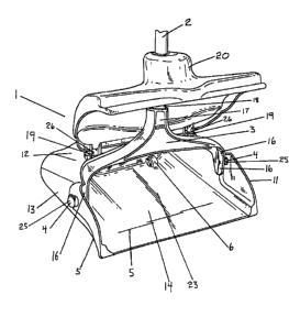
Fig. 1 is a frontal perspective view of a preferred dust pan according
to the present invention with a cover in an open position;
Fig. 2 is a left side view of the dust pan of Fig. 1 with the cover in an
open position;
Fig. 3 is a bottom side perspective view of the dust pan with the
cover in a closed position;
Fig. 4 is a top side perspective view of the dust pan with the cover in
a closed position;
Fig. 5 is a rear perspective view of the dust pan.
DETAILED DESCRIPTION OF THE PREFERRED EMBODIMENT
A preferred embodiment of a dust pan according to the present
invention is shown in Figs. 1-5. The dust pan includes a base 1, a
handling member 2, and at least one rolling member 7.
The base 1 preferably has five sides: a right side 11, a left side 13,
a top side 12, a bottom side 14, and a back side 15. The sides 11, 12, 13,
14, 15 define a cavity 23 into which dust, dirt, and other refuse can be
swept. The bottom side 14 has a well 6 for receiving a rolling member 7.
A single well 6 could be provided to receive one or more rolling members
7, but in the preferred embodiment shown in the drawings, a well is
provided for each rolling member 7. Also formed in the bottom side 14 is
a graded surface return 5 which is provided to maintain dust and other
refuse in the base after being swept into it. The top side 12 has a front
edge 8 which is substantially flat and a rear edge 9 which is substantially
curved.
Although the base has wells 6 and the surface return 5 formed in it,
the base 1 is designed so that the inner surfaces of sides of the base 11,
12, 13, 14, 15 form one substantially continuous surface. Rounding the
corners (which would otherwise be created by the joining of the sides of
the base 1) in the base to form the substantially continuous surface aids
CA 02322913 2001-O1-24
4
in cleaning the base by eliminating corners in which dirt, dust, and other
refuse may become trapped, especially if the refuse has a sticky nature.
In the back side 15 of the base 1, a slot 10 is preferably provided
slightly below the rear edge 9 of the top side 12. The slot preferably is
wide enough to receive four fingers. The user can hold the base 1 in a
desired position using the slot 10. For example, the user can hold the
bottom side 14 parallel to the ground while lifting the dust pan.
Additionally, when emptying the base 1 of its contents, a user can hold
base 1 via slot 10 and thereby be insulated from the contents which fall out
of the base 1 while it is being emptied. Insulating the user in this fashion
helps prevent the user from being contaminated by the contents of the
base. The ability to insulate the user is particularly advantageous in the
medical context in which refuse swept into the base 1 may contain bodily
fluids from which the user could contract a communicable disease.
The handling member 2 is preferably a shaft or rod. More
preferably, an ergonomic handle, such as the ergonomic handle made by
Rubbermaid Commercial Products LLC (part # 2534), may be provided as
part of the handling member 2. The cross section of the handling member
2 can have any shape. Moreover, although the handling member 2 is
preferably hollow (to reduce the overall weight of the dust pan), it may be
solid. If the handling member 2 has a circular cross sectional area and is
hollow, it will preferably have an elongated tubular shape.
A yoke 3 is preferably provided to connect the handling member 2 to
the base 1. A lower portion 16 of the yoke 3 can be pivotally attached to the
right and left sides 11, 13 of the base 1 by hinge pins 25 at pivot points 4.
The lower portion 16 of the yoke 3 is wider than an upper portion 17 of the
yoke 3 thereby giving the yoke 3 a substantially triangular shape. The
upper portion 17 is connected to a lower end 18 of the handling member
2. This connection can be established in numerous ways, such as
molding the upper portion 17 to the lower end 18 or, more preferably, by
providing complementary screw threads (not shown) on the upper portion
17 and the lower end 18.
CA 02322913 2001-O1-24
As shown in Fig. 5, the rolling members 7 on the base 1 are
preferably wheels. The rolling members 7 are provided to inhibit wear to
the bottom side 14 (particularly the rear corners and edge) of the base 1
when the base is raised from or lowered to the ground. The rolling
5 members 7 are of a small diameter, preferably 1_ inches.
The rolling members 7 inhibit wear to the bottom side 14 when the
base 1 is raised from and lowered to the ground by preventing the bottom
side 14 of the base 1 (particularly the rear portion) from scraping the
ground. For example, when the handling member 2 is raised, the front
portion 21 of the base begins to pivot upward toward the lower end 18 of
the handling member 2. The rear portion 22 of the bottom side 14 can roll
on the ground via the rolling members 7 as the base 1 pivots. Wear is
inhibited by allowing the rear portion 22 to roll, rather than scrape across
the ground. Similarly, when the base 1 is lowered to the ground, the
rolling members 7 are positioned to make initial contact with the ground,
causing the front portion 21 of the base 1 to begin pivoting downward. As
the user continues to lower the base 1 after the rolling members 7 contact
the ground, the rear portion 22 will roll via the rolling members 7 along the
ground as the front portion 21 continues to pivot downward. Due to the
rolling nature, wear to the bottom side 14 is inhibited.
A user can carry the assembly by the handling member 2. When
the user raises the handling member 2, the front portion 21 of the base 1
rises and swings in the direction of the lower end 18 of the handling
member 2. At the same time, the rear portion 22 of the base 1 initially
remains in contact with the ground. When the front portion 21 finishes its
swinging motion, the rear portion 22 will rise from the ground if the user
raises the handling member 2 high enough. The swinging motion of the
front portion 21 is achieved by means of the yoke 3 being pivotally attached
to the base 1 at pivot points 4. When the base 1 is raised off the ground,
the yoke 3 is substantially near the bottom side 14 of the base 1. On the
other hand, when the base 1 is laid flat on the ground, the yoke 3 is
substantially near the front edge 8 of the top side 12 of the base 1.
CA 02322913 2001-O1-24
6
A cover 20 is preferably provided on the base 1. The cover 20 can
be attached to the upper side 12 of the base 1 by means of hinge pins 26
located at clip points 19. In dust pans having a cover 20, the lower end 18
of the handling member 2 can be journalled through a cavity 24 in the
cover 20 thereby allowing the lower end 18 of the handling member 2 to
engage the upper portion 17 of the yoke 3. When the base 1 is on the
ground, the handling member 2 holds the cover 20 in an open position
(Fig. 1) thereby allowing a user to sweep dirt, dust, or other refuse into the
base. By way of contrast, when the base 1 is raised off the ground, the
handling member 2 forces the cover 20 into a closed position (Fig. 3) in
which the cavity 23 of the base 1 is enclosed thereby covering the refuse
held in the base 1.
To eliminate the undesirable boxy appearance of the conventional
dust pan, the base 1 has been substantially rounded in nature. In
accomplishing this objective, the right and left sides 11, 13 of the base 1
bend toward each other in the general direction from where they meet the
bottom side 14 to where they meet the top side 12. In addition, if a cover
is included it is rounded in two directions: in a general direction from
the front edge 8 toward the surface return 5 and in a general direction from
20 the right side 11 to the left side 13. Finally, the top side 12 is rounded
in
the general direction from the front edge 8 toward the rear edge 9; the rear
edge 9 itself is also rounded, as previously mentioned.
In making the dust pan hereinabove described, all parts are
preferably made from a light-weight plastic. By using light-weight plastic,
the overall weight of the dust pan can be reduced thereby easily allowing a
user to lift the base when emptying it or to carry the assembly when not in
use and to transport refuse.
Considering the aforementioned improvements, other obvious
improvements also fall within the scope of dust pan hereafter claimed.
For example the handling member may be attached to the base by
structure other than a yoke. In addition, various handles may be either
formed onto the handling member or releaseably attached thereto.
CA 02322913 2001-O1-24
7
Other embodiments of the invention will be apparent to those
skilled in the art from consideration of the specification and practice of the
invention disclosed herein. It is intended that the specification and
examples be considered as exemplary only, with a true scope and spirit of
the invention being indicated by the following claims.