Note: Descriptions are shown in the official language in which they were submitted.
CA 02322917 2000-10-06
TEM File No. 173.3
TITLE: TROLLEY AND TRAVELING BLOCK SYSTEM
s F FLD OF T INVENTInN
The present invention relates to drilling and servicing equipment for oil and
gas
wells generally, and in particular relates to a trolley hoisting system for
use in rigs which
transport and/or operate equipment for continuous coiled tubing drilling, for
conventional
joined pipe handling and drilling, and/or for wireline applications.
to
Our United States Patent 6,003,598 and corresponding Canadian Patent 2,235,555
for a "Mobile Multi-Function Rig" disclose a dual winch arrangement atop a
pivotable
derrick, or masts, for performing various functions relating to drilling and
servicing either
is oil or gas wells. One of the winch systems, namely the derrick or mainblock
winch, is
used to raise and lower certain equipment along the mast, such as an injector
and
lubricator for continuous or coiled tubing (referred to herein as "CT"). A
secondary, or
fastline, winch is used to manipulate other equipment, such as a blow-out-
preventer
("BOP"). For operations requiring use of a traveling block and elevators to
lift and lower
2o conventional joined pipe sections, the injector must first be brought to
rest at the bottom
of the mast and moved laterally out of the plane of the mast. The traveling
block and the
mainblock winch are then decoupled from the injector so that they are free to
manipulate
the joined pipe sections as in a conventional derrick.
-1-
CA 02322917 2000-10-06
We have not been able to locate or identify any conventional derricks, whether
they use a single winch or a similar multiple (i.e. two or more) winch system,
which would
allow one winch arrangement to handle multiple tasks without having to
decouple the
winch from the injector and remove the injector from the mast, or where the
injector
superstructure is not thereafter interfering with movement of the mainblock
winch lines
and the joined pipe or other downhole equipment being handled. In particular,
there are
time and labour costs associated with handling of the injector upon switching
tasks.
Removal of the injector from the plane of the mast to enable access and use of
a winch or
hoisting system is labour and time consuming. The costs and difficulties are
further
augmented if the winch line moving the injector must also be disconnected or
moved from
the injector mechanism before using it for another desired task. Further, in a
multiple
winch system where the primary winch line is not disconnected from the
injector, the
secondary winch is typically slower and has less capacity than the primary
line, leading to
further inefficiencies.
1s What is desired therefore is a novel trolley hoisting system for use in
rigs,
particularly mufti-task rigs, which transport and/or operate equipment for oil
and gas
operations, including continuous coiled tubing drilling and conventional
joined pipe
handling and drilling operations. The novel system should allow a single winch
arrangement to perform various task without having to detach from or connect
to the
Z« injector, as in some conventional rig arrangements, when switching between
tasks. In
particular, the winch system should be capable of moving the injector along
the rig's
derrick and, upon fixing the injector at a desired location along the derrick,
the winch
should be immediately available for performing other desired tasks, such as a
joined pipe
operation.
-2-
CA 02322917 2000-10-06
According to the present invention, there is provided in one aspect a trolley
hoisting system for use in a rig comprising a winch line extending from an
upper end of a
rig derrick having a traveling block at a lower end thereof, and an injector
housing having
at least one cavity for allowing the winch line passage therethrough and being
adapted to
engage the traveling block so that the winch line may be used to raise and
lower the
injector and injector housing along the derrick, and a lock arrangement for
fixing the
injector housing to the derrick at an upper end thereof to allow the traveling
block to
extend below the injector housing for performing other desired tasks on the
rig.
to
Embodiments of the invention will now be described, by way of example only,
with
reference to the accompanying drawings, wherein:
Figure 1 is a side view of a mobile mufti-function rig which employs a trolley
and
traveling block system according to a preferred embodiment of the present
invention
showing two selected locations of the injector when moved laterally out of the
plane of the
rig's derrick;
Figure 2 is an end view of the derrick of the rig of fig.l showing the
traveling
block supporting the trolley and injector in two selected locations;
2o Figure 3 is a view similar to fig. 2 but showing the injector fixed, or
"parked", at an
upper end of the derrick and the traveling block projecting downwardly from
the injector's
trolley for performing other desired tasks, such as manipulating pipe
sections;
Figure 4 is an enlarged perspective view of the injector and trolley
arrangement in
isolation, providing a closer view of a chimney for receiving the traveling
block;
-3-
CA 02322917 2000-10-06
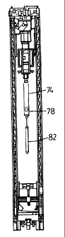
Figure 5 is a side view along line 5-5 of an upper portion of the trolley of
fig.4;
Figure 6 is a transparent view of fig.5 showing the traveling block supported
by its
cables exiting/entering a bottom end of the chimney; and,
Figure 7 is a cross-sectional view along line 7-7 of an upper portion of the
trolley
of fig.4 to show a safety lock mechanism of the present invention.
LIST
OF
REFERENCE
NUMBERS
IN
DRAWINGS
mobile rig
12 carrier
l0 front end of 12
14
16 rear end of 12
18 cab
cartridge assembly
22 ground surface
1 s wellhead
24
26 stabilizers
derrick
32 masts (2)
34 passage through masts
2t) crown of 30
36
3 8 hydraulic legs
39 hollow tubular member
safety lock mechanism
42 locating arms
-4-
CA 02322917 2000-10-06
44 locking pin mechanism
46 solenoid
48 pin
50 injector
52 trolley
54 tracks for 50
56 guide / chimney
58 hollow chamber
of 56
60 bottom opening
of 58
slots {4) above
62 58
64 top end of 56
66 openings on sides
of 52
70 winch assembly
72 winch / drive motor
1s control panel
73
74 steel cables
76 sheaves
78 traveling block
80 loop beneath 78
joined pipe
82
-5-
CA 02322917 2000-10-06
DF~('I~IpTION OF PI~F.FERRFD EMBODLMENTS
Figure 1 shows a mobile rig 10 for transporting drilling and servicing
equipment to
an oil or gas well site. The equipment, such as a cartridge assembly 20
capable of holding
various sizes of continuous or coiled tubing ("CT") reels, is located aboard a
self
s propelled carrier 12 having a tandem axle front end 14 and a triple axle
rear end 16. A cab
18 houses an engine for driving the front and/or rear axles, and incorporates
conventional
controls for steering the carrier over a ground surface 22 and for locating
the carrier's rear
end over a well. The term "well" is understood herein to mean either an oil or
gas well to
be drilled, or an existing well or wellhead 24 which is to be tested or
serviced. The carrier
12 incorporates a number of hydraulically operated stabilizers 26 for lifting
the carrier off
the ground and enhancing lateral stability during well operations. The front
and rear axle
designs may vary depending on the anticipated weight of equipment to be
carried and the
type of terrain to be encountered. The carrier's design is generally
symmetrical about its
longitudinal axis.
1 s The rig 10 incorporates a number of drilling and servicing features aboard
the
mobile carrier 12, including a derrick or mast 30 pivotally mounted to the
rear of the
carrier. The derrick is capable of supporting a blow out preventer ("BOP") and
an injector
50 for moving CT into and out of the well. The derrick also incorporates a
novel single
winch arrangement, generally designated by 70. An important advantage of the
rig of the
2o present invention over the prior art is that the single winch arrangement
70, in conjunction
with novel features of the trolley 52, is designed to perform multiple tasks,
such as raising
and lowering the injector and lubricator, as well as running joined pipe
segments, handling
various lengths of down hole tools, and hoisting other equipment as may be
needed,
including wireline equipment.
-6-
CA 02322917 2000-10-06
Referring now to the derrick 30 in some greater detail, it has two
longitudinally
spaced mast members 32 (as best seen in figs.2 & 3), each formed by a
triangular (in
cross-section) truss arrangement having a longitudinal central passage 34
along its length.
The masts 32 are joined at the top end by a generally hollow structural tie
member, or
crown 36, housing a pair of conventional pulley wheels (also referred to as
"drums" or
"sheaves") of the winch assembly 70. In the embodiment shown the sheaves are
grooved
to accept 7/8 inch (about 22 mm) wire rope or like cables. The derrick shown
is about 60
feet {about 18 m) in length from ground to crown so as to accommodate multiple
sections
of conventional joined pipe 82. A telescoping hydraulic cylinder or leg 38 is
attached to
each mast, and is operated from a control panel at the rear of the carrier, to
tilt the derrick
30 between a transportation mode and an operating mode, as set out in more
detail in
applicant's US Patent 6,003,598.
A drive unit, namely in this case a hydraulic winch 72, of the winch assembly
70 is
located underneath the carrier's deck and is operated via an upstanding
control panel 73.
The control panel 73 is folded out onto the side of the carrier when bringing
the derrick to
rest on the carrier's deck for transport. The winch 72 incorporates two sets
of steel cables
74, each set extending up a respective mast through its open passage 34 and
over a
respective sheave in the crown 36. The cables 74 then extend downwardly away
from the
crown and about respective rotatable pulleys or sheaves 76 which operatively
engage and
support a "traveling" block 78. The sheaves and block are sometimes referred
to as a
"block and tackle" arrangement. A loop element 80 is bolted to the bottom of
the block
78 for attaching and carrying drilling/servicing equipment or other loads. The
winch 72
therefore controls the movement of the traveling block 78 along the elevated
derrick 30
for performing desired functions.
_7_
CA 02322917 2000-10-06
Referring now more particularly to the injector 50, a cradle or trolley 52
supports
the injector and rides on the masts' rails 32 to guide the injector to any
number of desired
locations along the derrick, with two selected locations being illustrated in
figs. 1 & 2.
The trolley has a set of tracks 54 for moving the injector laterally (i. e.
perpendicularly to
the plane of the derrick) out of the derrick. In the embodiment shown, the
tracks 54
provide up to 54 inches of lateral movement, and the trolley is capable of
traveling along
the derrick whether the injector is located within the derrick or is slid
laterally out of the
plane of the derrick.
An important aspect of the present invention is the manner in which the
traveling
block 78 engages and moves the trolley along the derrick, and in which the
cables 74
extend through the trolley. Referring now to figs. 4 to 6, a central portion
of the trolley
52 has an upwardly extending trolley guide or sleeve 56 (also referred to as a
"chimney
stack"), with a hollow interior chamber 58 configured to receive the traveling
block 78
trough a bottom opening 60. Each winch cable 74 extends through a respective
one of
four spaced slots 62 in the top end 64 of the chimney 56. Hence, when the
traveling block
is located inside the chimney in an abutting relationship with the chimney's
top end 64 for
supporting the weight of the injector 50 and trolley 52, the winch assembly is
capable of
controlling the location and travel of the injector and trolley along the
derrick.
An additional feature of the present invention is a hydraulically and remotely
operated "safety lock" mechanism 40 below the crown of the derrick for
securely locking
the trolley to the top of the derrick as shown in fig.3. Referring as well to
fig.7 , the masts
incorporate a crown saver switching mechanism which is tripped by an upwardly
moving
trolley as it nears the crown 36 to slow the winch assembly and prevent
collision of the
trolley with the crown. Once tripped, the switching mechanism activates a pair
of locating
_g_
CA 02322917 2000-10-06
arms 42, one in each mast, to pivot outwardly from the respective masts
underneath the
trolley 52. The trolley is then lowered a short distance onto the locating
arms 42, allowing
the arms to take up the weight of the seated trolley. Such seating results in
alignment of
an opening 66 on each side of the trolley with a respective hollow tube 39
mounted on the
s masts. A locking pin mechanism 44 is mounted on the trolley adjacent each
opening 66.
A solenoid 46, or like hydraulic cylinder, is activated to extend a pin 48
through the
opening 66 and into the tube 39 to lock the trolley to the top of the derrick
at the location
shown. Sensors are provided for detecting/confirming that the pins are either
safely
engaged (or disengaged, as the case may be) with the mast. The injector is
then moved to
to a "parked" position out of the plane of the derrick (as illustrated in fig.
l), and the traveling
block 78 may now be lowered out of engagement with the chimney 56 and below
the
trolley for performing other tasks, such as running conventional joined pipe
80 if desired,
as illustrated in fig. 3. The safety lock mechanism 40 is preferably operable
from the same
console 73 as the trolley, and incorporates indicators which communicate with
the sensors
15 to confirm that the arms 42 and pins 48 are in their desired orientations,
either safely
engaged or disengaged with the trolley/masts, as the case may be. In addition,
the arms 42
have indicators thereon for additional visual confirmation from ground level
that the arms
42 are in their desired orientation.
An example of a typical multi-task operation for the rig 10 may now be
described.
2o With the derrick 30 in a raised and operative position, the traveling block
78 is pulled via
cables 74 into the trolley's chimney 56 and is tensioned so as to carry the
weight of the
trolley 52 and associated equipment, including the injector 50. With the
safety lock
mechanism 40 unlocked, the winch 72 is then used to move the trolley to a
desired
location on the derrick to perform a first set of tasks, such as CT
operations. When it is
-9-
CA 02322917 2000-10-06
desired to switch tasks which do not require use of the injector, such as a
joined pipe
operation, the winch mechanism pulls the traveling block, together with the
trolley and
injector, to the top of the derrick and the safety lock mechanism 40 is
activated to lock the
trolley in place with the locating arms 42 and the locking pin mechanism 44.
The injector
is moved out of the way along the tracks 54 into the parked position, allowing
the winch
to drop the traveling block 78 out of the chimney 56 and through the trolley
to perform
the joined pipe operation independently of the trolley. When the trolley and
injector must
be used again, the reverse steps are taken. The block 78 is brought back up
into the
chimney 56, weight is taken up by the cables 74, and the safety lock mechanism
40 is
to released (i.e. the solenoids 46 disengage the pins 48 and the locating arms
42 are moved
out of the way) to make the trolley operational.
It will now be appreciated that, among other advantages, the present invention
eliminates the need for a secondary fastline winch at the derrick's crown for
performing
other tasks, such as manipulating the BOP. The novel trolley and traveling
block system
1 s allows a single winch arrangement to perform various task without having
to detach from
or connect to the injector, as in some conventional rig arrangements, when
switching
between tasks. In particular, the present system is capable of moving the
injector along
the rig's masts and, upon fixing the injector at a desired location along the
masts, the
traveling block is immediately available for performing other desired tasks,
such as a
2o joined pipe operation.
The above description is intended in an illustrative rather than a restrictive
sense,
and variations to the specific configurations described may be apparent to
skilled persons
in adapting the present invention to other specific applications. Such
variations are
intended to form part of the present invention insofar as they are within the
spirit and
- 10-
CA 02322917 2000-10-06
scope of the claims below. For instance, it is understood that the trolley and
traveling
block system of the present invention is not restricted to use aboard a self
propelled
carrier, but may be used in conjunction with other arrangements of equipment,
such as on
a derrick aboard a trailer which is pulled by a tractor truck.
10
20
-11-