Note: Descriptions are shown in the official language in which they were submitted.
CA 02322930 2000-10-11
Riazi 2-10-2
SIGNAL COMBINING SCHEME FOR WIRELESS TRANSMISSION
SYSTEMS HAVING MULTIPLE MODULATION SCHEMES
Field Of The Invention
The present invention relates to wireless transmission systems.
Description Of The Related Art
Transmitted signals of a digital transmission system are usually configured to
a single
modulation scheme. The modulation scheme is often determined as a result of
the region in which
the signal is to be transmitted. For instance, time division multiplexed (TDM)
signals are typically
suited for rural areas whereas orthogonal frequency multiplexed (OFDM) signals
are typically
suited for urban areas.
TDM signals are suited for rural areas, where there is typically a clear line-
of sight (LOS)
between a satellite transmitter and a ground-based receiver. Often a time-
delayed signal may also
be transmitted to compensate for short-term signal outages that may occur when
there is an
obstruction in the LOS signal path (e.g., when a mobile receiver passes under
an overpass). In such
I S cases, after the direct LOS connection has been reestablished, any data in
the "on-time" LOS signal
that was lost during the temporary obstruction will be available from the time-
delayed TDM signal.
In urban areas, buildings and other structures form potentially long-lasting
LOS
obs~uctions. They also tend to act as a source of reflections leading to
multipath signal distortions.
Consequently, TDM-based service is often unacceptable in such urban areas.
Since OFDM
signals are well-suited for regions, such as urban areas, having LOS
obstructions and multipath
signals, OFDM signals are typically used.
Since each type of signal is ideally suited for different operating
conditions, it is typical to
use each signal only in the region suited for each signal. Additionally, it is
typical to encounter
increased noise at transition regions where, for example, a mobile receiver
may be changing
between TDM service and OFDM service. Noise at such transition regions often
causes signal
degradation, handoff failures, and signal losses, which detrimentally affect
the quality of the
service.
CA 02322930 2000-10-11
Riazi 2-10-2
Summary Of The Invention
The present invention is directed to a technique for improving the quality of
service for
wireless transmission systems that employ two or more different modulation
schemes to transmit
the same information in parallel, such as satellite-based digital audio
transmission systems that
transmit digital audio data using both TDM and OFDM modulation schemes.
In the satellite-based digital audio transmission system, two TDM signals and
one OFDM
signal are used. A transmitter transmits two TDM signals that carry the same
information, where
one signal is delayed in time (e.g., by a few seconds) in relation to the
other. The two TDM signals
are used to compensate for short-term signal outages that may occur when there
is an obstruction in
the LOS signal path (e.g., when a mobile receiver passes under an overpass).
The transmitter also
transmits an OFDM signal which is typically used as a terrestrial gap filler
signal for regions where
TDM signals do not provide acceptable service. In particular, OFDM signals
carrying the same
information as the TDM signals are transmitted in parallel with the TDM
signals, and terrestrial
OFDM repeaters are deployed to fill the regional gaps in the TDM service.
I 5 According to one embodiment of the present invention, for TDM/OFDM digital
audio
transmission systems, a TDM/OFDM transmitter transmits two TDM signals and a
single OFDM
signal that are then received at a receiver. The two TDM signals (i.e., the on-
time TDM signal and
the time-delayed TDM signals) and the single OFDM signal received at a mobile
receiver are
combined using suitable signal combining techniques to generate a single
combined signal for
subsequent signal processing (e.g., signal decoding). By combining the
differently modulated
signals, the adverse affects of noise in the individual signals can be
reduced. As a result, the
occurrence of signal losses and handoff failures may also be reduced.
In general, the principles of the present invention can be applied to improve
the quality of
service for any signal transmission system that uses two or more different
modulation schemes to
transmit the same information in parallel. Satellite-based digital audio
transmission systems based
on TDM and OFDM modulation schemes are just one particular application of the
present
invention.
In one particular implementation of the present invention for a TDM/OFDM
digital audio
transmission system, the two TDM signals (i.e., the on-time TDM signal and the
time-delayed
TDM signals) and the single OFDM signal are received at a receiver, where they
are demodulated
and combined using a maximal ratio combining (MRC) technique to generate a
combined signal for
CA 02322930 2000-10-11 -- -
Riazi 2-10-2
further processing (e.g., decoding). The combining of the two differently-
modulated signals
reduces the adverse effects of noise, thereby improving quality of service.
In one embodiment, the present invention is a method for processing wireless
signals,
comprising the steps of (a) receiving two or more wireless signals containing
a common set of
information and conforming to two or more different modulation schemes; (b)
demodulating each
of the received wireless signals using a corresponding different demodulation
scheme; and (c)
combining the two or more demodulated signals using a signal combining
technique to generate a
combined signal.
In another embodiment, the present invention is an apparatus for processing
wireless
signals, comprising (a) an antenna, configured to receive an analog signal
corresponding to two or
more wireless signals containing a common set of information and conforming to
two or more
different modulation schemes; (b) a converter, electrically connected to the
antenna and configured
to convert the analog signal to a baseband signal; (c) a separator,
electrically connected to the
converter and configured to separate the baseband signal into two or more sub-
signals '
corresponding to the two or more wireless signals; (d) for each sub-signal, a
demodulator
electrically connected to the separator and configured to apply demodulation
processing
corresponding to the modulation scheme for the corresponding sub-signal; (e) a
synchronizer,
electrically connected to each demodulator and configured to synchronize each
demodulated sub-
signal; and (fj a signal combiner, electrically connected to the synchronizer
and configured to
combine the two or more demodulated sub-signals using a signal combining
technique to generate a
combined digital signal.
Brief Descriution Of The Drawings
Other aspects, features, and advantages of the present invention will become
more fully
apparent from the following detailed description, the appended claims, and the
accompanying
drawings in which:
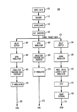
Figure 1 shows a block diagram of a transmitter for a satellite-based
transmission system
utilizing both TDM and OFDM signals, according to the present invention.
Figure 2 shows a block diagram of a receiver according to one embodiment of
the present
invention.
CA 02322930 2000-10-11
Riazi 2-10-2
Figure 3 shows details of the synchronizing block generating inputs to the
combining block
of Figure 2.
Detailed Description
The present invention may be implemented in a one-way digital audio
transmission system
(e.g., digital radio) that uses two or more differently-modulated signals,
such as TDM and OFDM
signals to transmit the same information in parallel using adjacent frequency
bands. More
particularly, in a preferred embodiment of the present invention, two TDM
signals (an on-time
signal and a time-delayed signal) and a single OFDM signal, are combined using
a maximal ratio
combining technique to generate a single combined signal for subsequent signal
processing (e.g.,
signal decoding). Accordingly, the adverse affects of noise related e.g., to
inter-symbol interference
in the individual signals is reduced as is the occurrence of signal losses and
handoff failures. For
the present invention, there is a reduced need for receiver complexity and
receiver hardware since a
single de-interleaver and a single channel decoder may be used for all three
of the received signals.
Figure 1 shows a block diagram of a TDM/OFDM transmitter 100 of the present
invention. The transmitter 100 is a common source for two TDM signals -- TDM 1
175 and TDM2
185 -- and one OFDM signal 155. The first TDM signal 175 is an on-time signal,
and the second
TDM signal 185 is a time-delayed signal. The input data is formatted and
transmitted by the
transmitter 100 such that the different signals may be received at a receiver
(not shown in Figure 1 )
with acceptable differential delays.
The input data 105, which is typically binary data, is encoded by a channel
encoder 110 to
add redundancy to the data sequence. An interleaver 115 interleaves the
resulting encoded symbols
for output as interleaved symbols in packet data frames. A bit inserter 120
inserts synch bits into
the packet data frames to generate synchronized packet data 125. Frame
synchronization is
generally known in the art, and other synchronization methods may be
additionally or alternatively
used in the present invention. Copies of the synchronized packet data 125 are
then processed in
parallel to generate the three output signals for parallel transmission: OFDM
signal 155, TDM1
signal 175, and TDM2 signal 185.
In particular, the TDM 1 signal 175 is generated by modulating one copy of the
synchronized packet data 125 at a quadrature-phase shift-key (QPSK) modulator
160, inserting
equalizer training symbols at regular intervals (e.g., every 1 cosec) at an
equalizer training sequence
CA 02322930 2000-10-11
Riazi 2-IO-2
inserter 165, and further modulating using an IF modulator 170 to position the
signal in the desired
band.
The TDM2 signal 185 is generated using an analogous sequence of QPSK modulator
160,
equalizer 165, and IF modulator 170, but before doing so, the corresponding
copy of the
synchronized packet data 125 is delayed at delay buffer 180 for a specified
time (e.g., about 4
seconds). This delay is added to the second TDM signal to provide continuity
of data to a mobile
receiver which is temporarily blocked by an obstacle.
For the OFDM signal 155, the corresponding copy of the synchronized packet
data 125 is
also delayed at a delay buffer 130 for a specified time that is preferably
identical to the delay used
in generating the TDM2 signal 185. By using the same delay for both the OFDM
signal 155 and
the TDM2 signal 185, a receiver of all three transmitted signals will only
have to buffer the first
on-time TDM 1 signal 175. The delayed signal is then modulated at differential
QPSK (DQPSK)
modulator 135 to produce a DQPSK constellation. The data is then modulated by
a differential
modulator over frequency 140 and encoded by an inverse fast Fourier transform
(IFFT) 145 which
outputs a complex function having imaginary and real parts. A guard interval
(GI) is introduced at
a guard interval block 150 to mitigate channel multipath effects. The duration
of the guard interval
is preferably greater than the maximum expected delay spread of the channel.
Figure 2 shows a block diagram of a receiver 200, according to one embodiment
of the
present invention. In general, the received signal is first converted to
baseband and is then
separated into its corresponding bands. Alternatively, the received signal is
separated into its
corresponding bands before converting the signal to baseband. Equalizing
symbols and guard
intervals are removed as necessary, and the signals are demodulated in
accordance with their
particular modulation scheme. Time delays are added to synchronize the
demodulated signals as
needed. The time-aligned outputs are then combined using a maximal ratio
combining technique to
generate a single signal output for subsequent decode processing.
In particular, the signal 203 received at an antenna 206 is converted to
baseband data by a
converter 209. A separator 212 then separates the converted baseband output
into three bands 215,
230, and 236, corresponding to the TDMI, TDM2, and OFDM signals, respectively.
Each of TDM 1 215 and TDM2 230 is equalized as a complex function by an
equalizer 218
which also removes the equalizer training symbols by a stripping function
implemented within the
CA 02322930 2000-10-11 '
Riazi 2-10-2 6
equalizer 218. The complex output from each equalizer 218 is then demodulated
by a QPSK
demodulator 221. Since the TDM2 signal is delayed with respect to the TDM 1
signal, after
demodulator 221, the TDMl data is delayed at a delay buffer 224 by an amount
equivalent to the
delay of the TDM2 signal (e.g., 4 seconds) to synchronize the two TDM signals.
The two resulting
TDM signals 227 and 230 are input into a signal synchronizing block 257.
For the OFDM signal, following separation at the separator 212, the guard
interval on the
OFDM signal 236 is removed by a guard interval stripper 239. Once removed, the
differentially
modulated data of the OFDM signal 236 undergoes a fast Fourier transform (FFT)
operation 242
to recover the differentially modulated data. The output of the FFT operation
is then differentially
demodulated by a differential demodulator 245. The output from the demodulator
245 is then de-
interleaved by a frequency de-interleaver 248 to separate sub-carnets from the
resulting de-
interleaved signal. The output de-interleaved signal is then DQPSK-demodulated
by a DQPSK
demodulator 251, resulting in a mapping of real and imaginary soft bits in the
OFDM signal output
254, which is also input into the signal synchronizing block 257.
CA 02322930 2000-10-11 ---
Riazi 2-10-2 7
Each of the demodulated signals 227, 233, and 254 is a complex digital signal
having an
imaginary part and a real part, wherein each may therefore be represented as a
complex vector
function in a complex plane having imaginary and real axes. In the
synchronizing block 257, each
of the demodulated signals 227, 233 and 254 is time-aligned, has synch bits
removed, and is
weighted by its signal-to-noise ratio (SNR) such that the three signals are
output from the
synchronizing block 257 as TDM1 signal 260, TDM2 signal 263, and OFDM signal
266 as input
to the combining block 269. Combining block 269 combines the three time-
aligned. SNR-weighted
signals 260, 263, and 266 to generate a combined output signal 272. In a
preferred embodiment,
the combining block 269 employs a maximal ratio combining technique to
generate an optimal
ratio combined signal 272, which is then input into a channel decoder 275
whose output is stored in
a data sink 278. In an MRC technique, signals are combined according to
r~*sqrt(SNR,) +
rz*sqrt(SNRZ) + r3*sqrt(SNR3), in which each r represents data information in
the corresponding
signal and each SNR is the signal-to-noise ratio estimate for the
corresponding signal obtained as
described further below.
Figure 3 shows details of the synchronizing block 257 of Figure 2. Each of the
demodulated signals 227, 233, and 254 is time synchronized by a data
synchronizer 300, and has
synch bits removed by a bit stripper 310. The output signal from each stripper
310 is then
weighted by its signal-to-noise ratio (SNR). For example the time-aligned,
demodulated OFDM
signal 380 is multiplied at a multiplier 330 by its respective SNR factor to
SNR-weight the signal.
SNR estimation is known in the art. It is known to estimate SNR values for TDM
signals
such as 227 and 233. For example, it is known to obtain an SNR estimate for a
TDM signal by
obtaining the a priori knowledge of the synch symbols of the signal and
estimating the noise from
the hard decisions of the signal following demodulation. Each TDM signal is
then SNR-weighted
in relation to its respective SNR estimate as determined by the equalizer
block 218.
Similarly, SNR estimation for OFDM signals is known in the art and is often
estimated by
known algorithms. As an example, an SNR estimate may be determined in relation
to the complex
output of a demodulator and its sub-carrier gain. Other methods of SNR
estimation are known and
are incorporated herein. It is desired to weight the OFDM demodulated soft
bits in relation to the
power and the SNR estimates for each signal, thereby utilizing the signal's
complex nature and
rotation to the first quadrant, then a majority of the signal lies on the real
axis and the noise is
predominately concentrated in the imaginary axis. The demodulated and time-
aligned OFDM
signal 380 is weighted in relation to the square root of the product of the
SNR estimate 340 and the
CA 02322930 2000-10-11 - '
Riazi 2-10-2
power ratio 350. The power ratio 350 is the ratio of the OFDM signal power to
the average power
of the two TDM signals. As such, a product factor is determined at the
multiplier 360 as a result of
the SNR estimate 340 multiplied by the power ratio 350. The value of the
square root 370 of the
product factor is then determined. The time-aligned, demodulated OFDM signal
380 is then SNR-
weighted by multiplying the result of 370 with the signal 380, resulting in
signal 266.
In the preferred embodiment of the present invention, all three of the signals
are operating
at the same coded data throughput rate. The duration of the training sequence,
the training-
sequence-to-data-sequence length ratio, and the guard interval may be
predetermined for each
signal to ensure that the three received signals, following digital
demodulation, produce the same
encoded data stream with independent noise and channel distortion at a
constant rate.
While the exemplary embodiments of the present invention have been described
with
respect to processing of OFDM and TDM signals, including possible
implementation as in an
audio transmission system, the present invention is not so limited. As would
be apparent to one
skilled in the art, various other signals and modulation schemes, including
QAM and higher order
1 S PSK, may also be used. Additionally, signal combining techniques other
than MRC may also be
implemented such as switched combining, which selects the best signal and
prevents the poorer
signal from entering the combiner.
The present invention may be implemented as circuit-based processes, including
possible
implementation on a single integrated circuit. As would be apparent to one
skilled in the art,
various functions of circuit elements may also be implemented in the digital
domain as processing
steps in a software program. Such software may be employed in, for example, a
digital signal
processor, micro-controller, or general-purpose computer.
While the exemplary embodiments of the present invention have been described
with
respect to processes of circuits, including possible implementation as a
single integrated circuit, the
present invention is not so limited. As would be apparent to one skilled in
the art, various functions
of circuit elements may also be implemented in the digital domain as
processing steps in a software
program. Such software may be employed in, for example, a digital signal
processor, micro-
controller, or general purpose computer.
The present invention can be embodied in the form of methods and apparatuses
for
practicing those methods. The present invention can also be embodied in the
form of program code
embodied in tangible media, such as floppy diskettes, CD-ROMs, hard drives, or
any other
CA 02322930 2000-10-11
Riazi 2-10-2
machine-readable storage medium, wherein, when the program code is loaded into
and executed by
a machine, such as a computer, the machine becomes an apparatus for practicing
the invention.
The present invention can also be embodied in the form of program code, for
example, whether
stored in a storage medium, loaded into and/or executed by a machine, or
transmitted over some
transmission medium or carrier, such as over electrical wiring or cabling,
through fiber optics, or
via electromagnetic radiation, wherein, when the program code is loaded into
and executed by a
machine, such as a computer, the machine becomes an apparatus for practicing
the invention.
When implemented on a general-purpose processor, the program code segments
combine with the
processor to provide a unique device that operates analogously to specific
logic circuits.
It will be further understood that various changes in the details, materials,
and
arrangements of the parts which have been described and illustrated in order
to explain the nature
of this invention may be made by those skilled in the art without departing
from the scope of the
invention as expressed in the following claims.