Note: Descriptions are shown in the official language in which they were submitted.
CA 02323113 2000-09-06
WO 99/46910 PCT/US99/04817
ADAPTIVE TELEPHONE HANDSET INTERFACE
Field of the Invention
This invention relates to the field of telephony. More particularly, this
invention
relates to an adaptive interface for interfacing a two-wire analog telephone
instrument, such
as a modem, fax modem, facsimile machine or teleconferencing device, to
telephone set
through a four-wire handset port of the telephone set.
Background of the Invention
A two-wire telephone set includes a base unit connected to a central office of
a
telephone service provider via a two-wire telephone line and also includes a
handset
connected to the telephone base via a four-wire handset cable. The handset
cable has four
wires because, for two-way voice communication, the handset includes both a
microphone
and a speaker, each of which requires a pair of wires. Typically, the
telephone base
supplies audio signals to the speaker and a DC biasing voltage to the
microphone, while
the telephone base receives audio signals from the microphone. A two-wire to
four-wire
converter included in the telephone set converts the two central office
signals into the four
handset signals. In addition, the telephone set includes a ring detector for
detecting an AC
ring signal provided by the central office and a hook-switch for signalling
the central office
of the on-hook/off hook status of the telephone set. The hook switch controls
draw of DC
current from the central office by the telephone set, which is sensed by the
central office.
A conventional modem transmits digital data over a two-wire telephone line by
modulating an analog carrier signal according to the digital data. Typically,
the digital data
is' generated by ~a computer or facsimile machine connected to the modem. The
carrier
signal is a tone within the frequency range of telephone transmission line.
Upon reception
by a second modem at the other end of the transmission line, the digital data
is
reconstructed by demodulating the received signal.
Business organizations often utilize a private branch exchange (PBX) for
providing
telephone service to telephone users within the organization. Telephones
located on the
desks of the users are each connected to the PBX while the PBX is connected to
a
telephone service provider via one or more outside lines. The PBX typically
includes
capability for appropriately connecting incoming calls to the user telephone
sets and for
-1-
CA 02323113 2000-09-06
WO 99/46910 PCT/US99/04817
connecting outgoing calls from a user telephone set to an outside line. In
this way, fewer
than one outside line per user telephone is needed, thus, reducing the cost of
the telephone
service. In addition, the PBX typically provides a variety of features to the
users of the
PBX, such as connecting calls among the users and providing voicemail
services.
To implement all of the functions of the PBX, certain control and overhead
communications must take place between each user's telephone set and the PBX.
These
communications typically include digital status and command signals in
addition to the
two-way voice signals necessary to carry on a telephone conversation. For
example, the
PBX must know whether a telephone set is connected to a particular extension
in order to
know whether or not to route calls to that extension. As another example, the
PBX must
interact with the user telephone sets in order for the users to initiate and
terminate
telephone calls and to access voicemail and other features of the PBX.
In general, the protocol utilized for control and overhead communications
differs
among the various manufacturers of PBX's. In addition, the voice signals can
be digitally
1 S sampled and compressed according to various different companding schemes
(e.g. p-law or
A-law). Therefore, a two-wire analog telephone instrument, such as modem, fax
modem,
facsimile machine or teleconferencing device, cannot generally interface
directly with the
PBX without a dedicated analog port from the PBX.
This creates a problem for users of a PBX who wish to use universally
available
analog telephone instruments, such as modems, fax modems, facsimile machines,
teleconferencing devices, headsets or handsets, in addition to their PBX-
compatible
telephone sets. This problem has intensified by a recent increase in demand
for access to
the world wide web, which is typically accessed through use of a modem
connected to a
personal -computer. A proposal has been to provide a dedicated outside line
for each such
analog telephone instrument. This solution is not entirely satisfactory,
however, because it
negates the savings which result from the PBX limiting the number of required
outside
lines. Another solution has been to provide an analog line card in the PBX and
a separate
line connecting the two-wire analog telephone instrument to the PBX. This
solution can be
costly due to the need to install separate extension lines to connect each of
the PBX-
compatible telephone set and the analog telephone instrument to the PBX.
Further, the
addition of analog line cards can necessitate a PBX that is has a higher
capacity, and
hence, higher cost, that would otherwise be required.
-2-
CA 02323113 2000-09-06
WO 99/46910 PC"T/US99/04817
Another solution has been to provide a device which interfaces a modem with a
telephone set through the handset port of the telephone set. For example, U.S.
Patent No.
4,907,267 discloses a modem interface device for use with a telephone set
having a base
unit and a handset. The telephone set can be a two-wire telephone set or a
telephone set
designed for use with a PBX. To use the modem interface device, the handset is
unplugged from the handset jack of the base and plugged into a handset jack in
one end of
the device. Extending from the device is a four-wire cable which is connected
to the
handset jack of the base. The device also includes a modular jack for
accepting a two-wire
cable which connects the device to a two-wire telephone instrument, such as a
modem. A
series of switches are manually positioned to select between voice and data
communications and to configure the interface device to match the signalling
characteristics
of the particular telephone set being used.
The manually operable switch arrangement described in U.S. Patent 4,907,267 is
improved upon in two products manufactured by Unlimited Systems Corp. of San
Diego,
California. A first of these products, the "KONEXX Office Konnector," connects
to the
base of a telephone set and to the handset to provide an interface for a two-
wire telephone,
facsimile machine or modem. The device detects when the two-wire telephone,
facsimile
machine or modem is placed off hook for switching between voice and data
communications. A second of the these products, the "KONEXX Konference," is
similarly
connected between the base and handset, but provides an interface for a
teleconferencing
device. For each of these devices, a manually operable switch is positioned in
one of four
positions for adjusting the device to the signalling characteristics of the
particular telephone
set being used.
pw~ w w ' ° ~ ° ° ° Awdrawback to
theaforementioned interface devices is that-the switch positions .rnay,~ ,-
be incorrectly set. In addition, there is a likelihood of encountering a
telephone set having
signalling characteristics that cannot be met by these interface devices. For
example, the
bias voltage level and AC signal coupling characteristics of the microphone
connection to
the telephone base can vary from manufacturer to manufacturer as well as the
output
impedance and signal levels provided via the handset speaker connection. Also,
the wire
assignments within the handset cable can vary. A single return may be provided
for both
the microphone and speaker or each may have two dedicated wires. Failure of an
interface
device to properly match the signalling characteristics of the telephone set
may result in
-3-
CA 02323113 2000-09-06
WO 99/46910 PCT/US99/04817
inoperability or lost data and may result in the frustration of users of such
devices who
may not have the technical ability, nor the inclination, to resolve such
problems.
What is needed is a telephone handset interface that has sufficient
flexibility to
match the signalling characteristics of a wide variety of commercially
available telephone
sets while minimizing technical ability required from a user of such
interface.
Summary of the Invention
The invention is an adaptive handset interface method and apparatus for
interfacing
a two-wire analog telephone instrument, such as a facsimile machine, fax
modem, modem
or teleconferencing device, to a telephone set having a base unit coupled to a
handset via a
four-wire handset cable. The interface device is suitable for use with a
variety of
telephone sets produced by different manufacturers despite differences in
signalling
characteristics between the base and the handset. This is because, upon
initiation of a
learning technique, the interface device automatically adapts itself to
variations in signalling
characteristics between the telephone base and handset among the different
telephone
manufacturers.
The interface device incorporates three different techniques for learning, and
adapting to, the signalling characteristics of the four-wire interface found
in most telephone
sets: a self contained technique which is executed under control of a
controller circuit
contained within the interface device; a technique which requires the user to
dial a
telephone number to couple the interface device to an automated host system
which then
controls the learning process; and a technique which requires the user to dial
a telephone
number and, then, a technician controls the learning process. The latter two
of the three
~~ w ° ' ' ~~ w' techn~iques~arerused only f-the self contained
technique is not completely successful.-
To use the interface device, the handset is unplugged from the handset jack of
the
telephone base and plugged into a handset jack of the interface device. Thus,
the device is
coupled to the four wires of the handset. In addition, a four-wire cable is
plugged into a
telephone base jack of the interface device and into the handset jack of the
telephone base.
Thus, the interface device is coupled to the four handset connections of the
telephone base.
The interface device also includes a modular jack for accepting a two-wire
cable for
coupling the interface device to the two-wire analog telephone instrument. The
jack forms
-4-
CA 02323113 2000-09-06
WO 99/46910 PCTNS99/04817
an interface port for interfacing with the two-wire analog telephone
instrument and is
preferably a type RJ-11 jack.
The self contained learning technique first requires that the user lift the
handset
from its cradle. The user then initiates the learning technique by pressing a
momentary-on
button located on the interface device. Because the handset is uncradied, a
dial tone
appears as an AC voltage across the two speaker wires from the handset jack of
the
telephone base. All four wires from the handset jack of the telephone base are
coupled to
a resistive shunt array and, then, routed through a cross-point switch matrix.
The controller
circuit manipulates the resistive shunt array and the cross-point switch
matrix to select pairs
of the four wires from the telephone base until the dial tone is sensed by the
controller
circuit. This determines which of the four wires from the telephone base are
the two
speaker wires. The cross point switch matrix is configured to couple the two
speaker wires
to a differential amplifier. The output of the differential amplifier is
coupled to an
attenuator circuit which selectively and incrementally attenuates the signal
under control of
the controller circuit. From the attenuator, the signal is amplified to an
appropriate
amplitude under control of an automatic level control circuit, forming a
single-ended
receive output signal. The resistive shunt array, cross-point switch matrix,
differential
amplifier, attenuator and automatic level control circuit comprise a receive
signal path
within the interface device.
The remaining two of the four wires are presumed to be the two microphone
wires.
The cross-point switch matrix and resistive shunt array are configured to
transmit a signal
on a selected one of these signal lines from a transmit signal path within the
interface
device, while the other of these two signal lines is configured as a transmit
signal return.
r~ ~° The transmit path comprises~~a pre-amplifier for receiving
axtransmit.input Signal, ~an ,. . .
expander level detection circuit and a voltage controlled amplifier (VCA)
circuit coupled to
the output of the pre-amplifier, an incrementally selectable attenuator (step
attenuator)
coupled to the VCA output, and finally, an output amplifier circuit coupled to
the output of
the step attenuator.
To calibrate the transmit path, a tone is generated from the controller
circuit and
applied to the transmit path via a calibration circuit coupled to the VCA and
expander
circuits. The controller circuit monitors the receive signal path; due to side
tone
characteristics existing at the handset port of the telephone set, the
transmit path can be
-5-
CA 02323113 2000-09-06
WO 99/46910 PCTNS99/04817
calibrated by monitoring the receive signal path. For this reason, the receive
signal path is
calibrated first. The elements of the transmit path are adjusted by the
controller circuit
according to the calibration signal to form a single-ended transmit output
signal of an
appropriate amplitude.
A pair of switching relays are provided for switching between coupling the
handset
and the two-wire analog telephone instrument to the handset jack of the
telephone base.
Each relay switches two of the four wires. A switch control circuit controls
the position of
the relays according to whether a DC current is drawn by the two-wire
telephone
instrument. If the instrument is off hook, it will draw a DC current. In
response to the
off hook condition, the controller circuit configures the switching relays to
couple the two-
wire telephone instrument to the handset jack of the telephone base and to
decouple the
handset from the handset jack. If the two-wire telephone instrument is on-
hook, it will
draw a negligible amount of DC current. In response to the on-hook condition,
the
controller circuit will configure the switching relays to couple the handset
to the handset
jack of the telephone base and to decouple the instrument from the handset
jack.
Brief Description of the Drawings
Fig. 1 illustrates a perspective view of the interface device according to the
present
invention coupled to a telephone set and to a two-wire analog telephone
instrument.
Fig. 2 illustrates a block schematic diagram of the interface device according
to the
present invention.
Fig. 3 illustrates a flow model of a "Central Office (CO) Dialtone Learning
Sequence."
. . , ".,p" . .~ .- Fig: ~villustrxtes a flow model of an "Automated 800
Learning Method." ..
Fig. 5 illustrates a diagram of the SIT Data Transmission technique used for
the
"Automated 800 Learning Method" and "Manual 800 Learning Method" of the
present
invention.
Fig. 6 illustrates switching algorithms for the system.
Fig. 7 is a continuation of the switching algorithms of Fig. 6.
Fig. 8 illustrates a block diagram of the regulated and non-regulated portions
of a
typical telephone interface configuration as it relates to both the Central
Office and the
interface device of the present invention.
-6-
CA 02323113 2000-09-06
WO 99/46910 PCT/US99/04817
Fig. 9 illustrates a block schematic diagram of the interface device including
a full-
custom analog and semi-custom digital microcontroller integrated circuit.
Fig. 10 illustrates a block diagram of the full-custom analog integrated
circuit of the
present invention.
Fig. 11 illustrates a block diagram of 4x4 cross-point switch and shunt
resistor
arrays.
Detailed Description of the Preferred Embodiment
Fig. 1 illustrates a perspective view of the interface device 100 according to
the
present invention coupled to a telephone set 102 and to a two-wire analog
telephone
instrument 104, such as a facsimile machine, fax modem, modem or
teleconferencing
device. The telephone set 102 includes a handset 106 and a telephone base 108.
The
telephone set 102 can be configured to interface with a two-wire local loop or
with a
private branch exchange (PBX). The handset 106 is normally connected via a
handset
cable 110 to a handset port 112 of the telephone base 108. In Fig. 1, however,
the handset
cable 110 is disconnected from the handset port 112 and coupled to the
interface device
100 via a handset port 114 of the interface device 100. The handset port 112
of the
telephone base 108 is coupled to a phone port 116 of the interface device 100
via a
telephone base cable 118.
Located on the interface device 100 is a push-button 120, three diodes 122-124
and
a slide switch 126, whose functions are explained herein. The two-wire
telephone
instrument 104 is coupled to a two-wire telephone instrument port 128 of the
interface
device 100 via a cable 130.
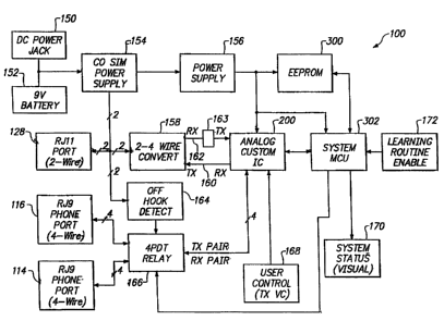
~,ig, 2 ~i~llustrates~ a block sehernatic diagramv ~of the interface device
100 according to . -
the present invention. The handset port 114 preferably includes an RJ-9 jack
provided for
coupling the interface device 100 to the telephone handset 106 (Fig. 1 ) via
the cable 110
(Fig. 1). The phone port 116 preferably includes an RJ-9 jack provided for
coupling the
interface device 100 to the telephone base 108 (Fig. 1 ) via the cable 118
(Fig. 1 ). The
two-wire telephone instrument port 128 preferably includes an RJ-11 jack
provided for
coupling the interface device 100 to the two-wire telephone instrument 104
(Fig. 1 ) via the
cable 130 (Fig. 1 ).
CA 02323113 2000-09-06
WO 99/46910 PCTNS99/04817
Power from an AC source is coupled to a DC power port 150 for providing power
to the interface device 100 via an AC-to-DC power conversion circuit (not
shown). A
battery 152, such as a 9 volt battery, can also be coupled to provide power to
the interface
device 100. The battery 152 can be used to replace the AC source or can be
used as a
back-up in the event of power failure.
A first power supply 154 is coupled to receive power from one of the DC power
port 150 or the 9 volt battery. The power supply 154 is coupled to the port
128 for
providing power to the telephone instrument 104 (Fig. 1 ) by simulating a
central office
power supply. In addition, the power supply 154 is coupled for providing power
to a
second power supply 156. The power supply 156 is configured for supplying
power to
circuits of the interface device 100. In particular, the power supply 156 is
coupled for
providing power to an adaptive circuit 200, preferably a custom integrated
analog circuit,
to a memory 300, preferably an EEPROM, and to a controller circuit 302,
preferably a
digital micro-controller. In the preferred embodiment, the memory 300 is
available from
Microchip under part number 93LC46. The digital controller 302, analog
adaptive circuit
200 and memory 300 can preferably operate over a supply range of 3 to 5 volts
DC.
The port 128 is also coupled to a two-to-four wire converter 158. The
converter
158 converts the two-wire signals (bi-directional signal path) at the handset
port 114 into
separate transmit and receive signals paths 160, 162 (uni-directional signal
paths). The
signal paths 160, 162 is coupled to the adaptive circuit 200. In the preferred
embodiment,
the signal path 162 includes an automatic level control (ALC) circuit 163
which ensures
that the signal provided via the path 162 does not exceed -40 dBV for the
various DTMF,
data or voice signals expected to be presented by the analog telephone
instrument 104
through the port ~ °128: , .
The four to two wire conversion is effected by applying a single-ended receive
output signal from the adaptive circuit 200 into a transmit amplifier input
contained within
the two-to-four wire converter circuit 158. The output of this transmit
amplifier places the
receive signal onto the two-wire (tip-ring) lines at the interface port 128
(preferably RJ-11).
This signal is, therefore, combined at the port 128 with the transmit output
signal generated
from a transmitter contained with the two-wire analog telephone instrument 104
(Fig. 1 ).
The two-to-four wire converter 158 also contains a receiving amplifier which
detects
signals present on the two-wire (tip-ring) lines at the port 128. This
receiving amplifier
_g_
CA 02323113 2000-09-06
WO 99/46910 PCT/US99/04817
also contains a reference input from the transmit amplifier contained in the
two-to-four
wire converter 158 which is 180 degrees out of phase with the receive signal
presented
onto the two-wire (tip-ring) lines of the port I28. Consequently, the two-to-
four wire
receiving amplifier passes only the signal generated by the transmitter
contained within the
two-wire analog telephone instrument 104 (Fig. 1 ) and cancels the receive
signal presented
onto the two-wire (tip-ring) lines of the port 128. The output of the
receiving amplifier
contained within the two-to-four wire converter is then coupled to the input
of the transmit
channel of the adaptive circuit 200 for conditioning by the adaptive circuit
200 prior to
driving the transmit lines of the four-wire phone port I 16 coupled to the
base 108 (Fig. 1 )
of the telephone set 102 (Fig. 1). The two-to-four wire converter 158 is
preferably
implemented as an integrated circuit, while the adaptive circuit 200 is
preferably
implemented as a custom integrated circuit. The two-to-four wire converter 158
and the
two-wire analog telephone instrument 104 (Fig. 1 ) are preferably both powered
by the
central office simulator power supply circuit 154.
The port 128 is also coupled to an off hook detector 164. The off hook
detector
164 senses whether the telephone instrument 104 (Fig. 1 ) coupled to the port
128 is on-
hook or off hook by sensing whether DC current is drawn from the port 128 by
the
telephone instrument 104 for controlling a four-pole-double-throw relay 166.
The relay
166 is coupled to the handset port 114 via four conductors (two uni-
directional signal
paths). The relay 166 is also coupled to phone port 116 the via four
conductors (two uni-
directional signal paths). In addition, the relay 166 is coupled to the
adaptive circuit 200
via four conductors (two uni-directional signal paths).
When the telephone instrument 104 (Fig. 1 ) is on-hook, the relay 166 couples
each
°- of the fourwires of the handseteport 114 to the respective wires of
the phone port 116 and
decouples the adaptive circuit 200 from the phone port 116. Accordingly, when
the
telephone instrument 104 is on-hook, the telephone base 108 is operatively
coupled to the
handset 106 (Fig. 1 ) via the relay I 66. Further, when the telephone
instrument 104 is on
hook, a signal path between the telephone instrument 104 and the telephone
base 108 (Fig.
1) via the two-to-four wire converter 158 and the adaptive circuit 200 is
interrupted by the
relay 166.
Conversely, when the telephone instrument 104 is off hook, the relay 166
couples
each of the four wires of the phone port 116 to the adaptive circuit 200 and
decouples the
-9-
CA 02323113 2000-09-06
WO 99/46910 PCT/US99/04817
handset port 114 from the phone port 116. Accordingly, when the telephone
instrument
104 is off hook, the telephone base 108 is coupled to the telephone instrument
104 via a
signal path which includes the two-to-four wire converter 158, the adaptive
circuit 200 and
the relay 166. Also, when the telephone instrument 104 is off hook, a
microphone and
speaker within the handset are preferably inoperative.
The relay 166 is also controlled by the controller 302 under certain
circumstances.
In particular, the controller 302 manipulates the relay during execution of a
learning
technique explained herein.
A first user input 168 is coupled to the adaptive circuit 200. This input 168
preferably includes the slide switch 126 (Fig. 1 ) for providing the user with
an ability to
adjust the transmit volume for the transmit signal path through the adaptive
circuit 200.
The adaptive circuit 200 is also coupled to be controlled by the controller
302. The
controller 302 can include a finite state machine or a micro-processor, though
in the
preferred embodiment, the controller 302 includes a digital micro-controller
unit (MCU)
which operates according to a stored software program. Parameters used by the
controller
302 are stored in the memory 300. A status indicator 170 provides a visual
indication of
the operative status of the interface device 100, as explained in more detail
herein. The
indicator preferably includes the diodes 122-124. A second user input 172 to
the controller
302 initiates a learning technique during which the interface device 100
adapts to the signal
characteristics of the telephone set 102 (Fig. 1 ). The user input 172
preferably includes the
push-button 120 (Fig. 1 ).
The interface device 100 preferably incorporates three different techniques
for
learning the characteristics of the four-wire interface found in most
telephone sets: a self
contained-technique which isexecuted under control of the controller 302; a
technique .
which requires the user to dial a telephone number to couple the interface
device 100 to an
automated host system via the telephone base 108 (Fig. 1 ) which then controls
the learning
process; and a technique which requires the user to dial a telephone number
and, then, a
technician controls the learning process. The latter two of the three
techniques are
preferably used only if the self contained technique is not completely
successful.
Fig. 3 illustrates a flow model of the self contained technique ("CO Dialtone
Learning Method"). This is the primary method the interface device 100 uses to
"learn"
- 10-
CA 02323113 2000-09-06
WO 99/46910 PCT/US99/04817
the characteristics of the telephone interface. The "CO Dialtone Learning
Method" is
automatic and transparent to the end user.
Upon initial system power-up, such as the first time batteries are installed
in the
interface device 100, or upon the user pressing the push-button 120 (Fig. 1 ),
a "CO
Dialtone Search" routine is enabled to detect and locate a CO dialtone signal
on any
combination of the 4-wire interface lines from the telephone base unit 108 (at
phone port
116). The telephone set 102 (Fig. 1 ) is taken off hook, this causes an AC
dial tone to
appear across two. of the four wires of the phone port 11 b and causes the
relay 166 to
couple the four wires of the phone port 116 to the adaptive circuit 200. When
the CO
dialtone is detected, the "CO Dialtone Learning Method" will be fully enabled.
Preferably,
the only inputs required to initiate the learning process are pressing the
push-button (or
supplying power for the first time) and receiving a dialtone.
The "CO Dialtone Learning Method" is a one-time activation process. After a
successful "learn sequence" has been executed, the appropriate bit addressable
latch 1 (Fig.
10) settings are preferably read from the controller 302 and stored into the
EEPROM 300,
though other types of memory can be used. Subsequent CO dial tones will not
enable the
learning sequence unless a soft system reset is performed to re-enable the
learning routine.
The "CO Dialtone Learning Method" is re-enabled by a user depressing the push-
button
120 (Fig. 1 ), preferably for a minimum of five seconds, or by a soft system
reset which is
accessed remotely.
The "CO Dialtone Learning Method" starts with the location of the CO dialtone.
Location of the CO dialtone indicates the proper receive lines. The receive
input step
attenuator then adjusts the receive channel sensitivity based on reference
levels as described
v ~ v ~be~low: 'Phe 'transmit lines] are then selected and the transmit ~
output- step attenuator adjusts .
the transmit channel sensitivity based on reference levels.
Fig. 4 illustrates flow models for the technique which requires the user to
dial a
telephone number to couple the interface device 100 to an automated host
system
("Automated 800 Learning Method"). Due to the lack of regulation as it relates
to Key and
PBX system station sets, there is a wide variation of side tone
characteristics which may be
encountered. Consequently, it is possible that occasionally, the learning
method employed
by the "CO Dialtone Learning Method" may not provide optimal overall
performance of
the interface device 100. The "Automated 800 Learning Method" provides a very
accurate
-11-
CA 02323113 2000-09-06
WO 99/46910 PCT/US99l04817
means for the interface device 100 to "learn" the characteristics of a 4-wire
telephone port
interface.
The "Automated 800 Learning Method" involves interaction between a "Host"
system located at the termination of the accessed telephone line and the
interface device
100 located at the end user's location. The user places a call to a designated
telephone
number and is greeted by an "automated attendant" message. The message
instructs the
user to momentarily depress the push-button 120 (Fig. 1 ) and, then, press a
key on a
keypad of the telephone set 102 (Fig. 1 ). The keystroke interrupts the "auto
attendant"
message and the "Host" sends a preamble to the interface device 100. When the
preamble
is detected, the "Automated 800 Learning Method" is enabled.
The "Automated 800 Learning Method" interaction between the "Host" and
interface
device 100 is shown in the flow model illustrated in Fig. 4 and the "FSK Data
Transmission Diagram" is illustrated in Fig. 5. Thus, an FSK modem is built
into the
interface device 100 for communication during the "Automated 800 Learning
Method" or
the "Manual 800 Learning Method." The "Host" sends a preamble, for a
predetermined
amount of time, to the interface device 100 to initiate the "Automated 800
Learning
Method." The "Host" then sends a 1 KHz reference signal, for a predetermined
amount of
time, for setup/calibration of the interface device 100 which it compares to
an internal
reference and uses to ensure proper setup/calibration of the interface device
100 receive
channel. The interface device 100 then sends a 1 KHz signal to the "Host" in
incremental
amplitudes. When the incoming 1 KHz reference level is appropriate, the "Host"
sends a
level confirmation signal to the interface device 100 and a final "handshake"
is generated
between the "Host" and interface device 100 signifying completion of the
"Automated 800
Learning Method:" , ,
The "Automated 800 Learning Method" begins by searching for the preamble sent
by the "Host." Once the preamble is located, the proper receive lines are
located. The
receive channel sensitivity is then adjusted in comparison to a receive level
reference.
Upon locating the proper receive lines, the transmit lines are selected and
their sensitivity is
adjusted in comparison to a transmit level reference signal.
- 12-
CA 02323113 2000-09-06
WO 99/46910 PCTNS99/04817
A third and final interface method is the "Manual 800 Learning Method." This
method is used when either of the previously described learning sequences fail
to provide
optimal performance with a particular telephone port interface. The "Manual
800 Learning
Method" provides the user with the ability to interact with a trained
telephony technician
who has the ability to adjust virtually ail of the interface device 100
parameters remotely
with the use of a second "Host" system.
The "CO Dialtone Learning Method" and the "Automated 800 Learning Method"
each select the most common configurations which satisfy the system's
performance
criteria. Occasionally this may not be the optimal "line configuration"
selection for all
interface environments. Since there are no regulatory requirements governing
the specific
characteristics for 4-wire handset port interfaces, there is a range of
different
configurations. It is not uncommon for an electronic telephone set to contain
a handset
port interface that will operate with multiple "line-configuration" settings.
All of the
configurations will provide acceptable system performance, occasionally
however, a
particular configuration will be more susceptible to unwanted radio-frequency
interference
or electro-magnetic interference. In these cases, alternate combinations must
be selected
for optimal system performance.
Alternate combinations can be implemented by a user placing a call to a
technical
support staff member (tech) at a designated telephone number. After
determining the
problematic symptoms, the technician has the ability to enable the "CO
Dialtone Learning
Method," the "Automated 800 Learning Method" or the "Manual 800 Learning
Method"
modes of operation by sending the appropriate sequence preamble. In the
"Manual 800
Learning Method" mode of operation, the technician can directly manipulate and
change
~~ ° the parameters associated with the cross-point switch array 2, the
receive input step
attenuator RX-2 or the transmit output step attenuator TX-5 (Figs. 9 and 10).
A block diagram of the regulated and non-regulated portions of a telephone
interface configuration is illustrated in Fig. 8. The connection between the
Central Office
Lines of the telephone company 52 and either a telephone set 54 or a telephone
system 56
is regulated. Accordingly, telephone sets and systems from many manufacturers
can all be
connected directly to the Central Office lines 52. The connection between a
telephone
system 56 and a hybrid or digital telephone set 58 is not regulated. The
connection
between a telephone set 54 or 58 and an accessory 60 or 62 is also not
regulated.
-13-
CA 02323113 2000-09-06
WO 99/46910 PCTNS99/04817
Therefore, unless designed to interface, one manufacturer's accessory may not
operate with
another manufacturer's telephone set.
The present invention provides the interface device 100 which provides an
interface
between telephone instruments 60 or 62 and telephone base units 54 or 58,
having different
protocols. The interface device 100 allows a voice/data accessory 60 or 62 to
be used with
telephone base units 54 and 58 from multiple manufacturers, each having
different
protocols. Note that if the telephone instrument is a four-wire device 62,
then the two-to-
four wire converter 158 (Fig. 2) is unnecessary.
A block schematic diagram of the interface device 100 system of the present
invention is illustrated in Fig. 9. The preferred embodiment of the interface
device 100
includes a full-custom analog integrated adaptive circuit 200, a semi-custom
digital
microcontroller (MCU) 302, a 1-K serial EEPROM 300, an integrated circuit two-
to-four
wire converter 158, a four-wire telephone handset port 114 for coupling to a
telephone
handset 106 (Fig. l ), a four-wire phone port 116 for coupling to a telephone
base 108 (Fig.
1 ), a two-wire telephone instrument port 128 for coupling to a two-wire
analog telephone
instrument 104 (Fig. 1 ) and additional elements described in more detail
below. The two-
to-four wire converter circuit 158 is preferably an integrated circuit
available under part
number TEA1061 from Philips Electronics, though it will be apparent that
another two-to-
four wire converter, such as a another type of active converter or a
transformer, can be
substituted with appropriate modifications.
A first terminal of the DC power port 150 is coupled to a first terminal of a
voltage
regulator U6 and to a first terminal of capacitor C48. An output terminal of
the voltage
regulator U6 is coupled to a first terminal of a capacitor C30, to a first
terminal of a
w ~ resistor R29;wto ~ afirst terminal of a resistor R30, to a supply
terlriinal of a comparator
USB, to a first terminal of a capacitor C35, to an emitter of a pnp bipolar
transistor Q2, to
a cathode of a diode D6, to a cathode of a diode D7, and to a first coil
terminal of the
relay K1, to a first coil terminal of the relay K2, and to an input terminal
of a voltage
regulator U4. An output terminal of the voltage regulator U4 forms a supply
node, Vcc,
for supplying power to various other elements of the interface device 100, and
which is
coupled to first terminals of filter capacitors C31-C34.
A ground terminal of the DC power port 150, a second terminal of the capacitor
C48, a ground terminal of the voltage regulator U6, a second terminal of the
capacitor C30,
-14-
CA 02323113 2000-09-06
WO 99/46910 PCT/US99/04817
a second terminal of the capacitor C35 and a ground terminal of the voltage
regulator U4
are each coupled to a first ground node. A second terminal of the capacitors
C31, C32 and
C34 are coupled to a second ground node. A second terminal of the capacitor
C33 is
coupled to a third ground node. A resistor R44 is coupled between the first
ground node
and the second ground node. A resistor R51 is coupled between the second
ground node
and the third ground node.
A first terminal of the two-wire telephone instrument port 128 is coupled to a
first
terminal of a resistor R49. A second terminal of the resistor R49 is coupled
to a second
terminal of the resistor R29 and to a first terminal of a resistor R33. The
voltage regulator
U6 preferably provides a regulated voltage of approximately 10 volts DC which
when
supplied through a 147 ohm resistance {provided by R29 and R49) simulates the
power
typically supplied by a central office. This ensures that the power
requirements of the
telephone instrument 104 (Fig. 1 ) are met. The voltage regulator U4
preferably provides a
regulated voltage of approximately 4 volts DC for Vcc.
A second terminal of the resistor R33 is coupled to a first terminal of a
resistor
R38, to an LN (positive line) terminal of the converter 158, and to a first
terminal of a
resistor R36. A second terminal of the resistor R38 is coupled to a first
terminal of a
capacitor C40 and to a first terminal of a resistor R39. A second terminal of
the capacitor
C40 is coupled to an IR (receiving amplifier input) terminal of the converter
158. A
second terminal of the resistor R39 is coupled to a first terminal of a
resistor R46 and to a
first terminal of a resistor R47. A second terminal of the resistor R46 is
coupled to a
SLPE (DC resistance adjustment) terminal of the converter 158, to a first
terminal of a
capacitor C44, to a first terminal of a resistor R48 and to a non-inverting
input of the
comparator USB. , . , ..~ ... , , ,
A second terminal of the capacitor C44 is coupled to a first terminal of a
resistor
R40 and to a GAS1 (transmitting amplifier gain adjustment) terminal of the
converter 158.
A second terminal of the resistor R40 is coupled to a GAS2 (transmitting
amplifier gain
adjustment) terminal of the converter 158. A GAR (receiving amplifier gain
adjustment)
terminal of the converter 158 is coupled to a first terminal of a resistor
R41, to a first
terminal a capacitor C43 and to a first terminal of a capacitor C47. A MIC-
(inverting
microphone input) terminal of the converter 158 is coupled to a first terminal
of a capacitor
C46. A STB (current stabilizer) terminal of the converter 158 is coupled to a
first terminal
-15-
CA 02323113 2000-09-06
WO 99/46910 PCT/US99/04817
of a resistor R50. A REG (voltage regulator decoupling) terminal of the
converter is
coupled to a first terminal of a capacitor C45.
A second terminal of the port 128, a second terminal of the resistor R47, a
second
terminal of the resistor R48, a VEE (negative line) terminal of the converter
158, a second
terminal of the resistor R50 and a second terminal of the capacitors C45 and
C47 are
coupled to the first ground node. A second terminal of the capacitor C46 is
coupled to the
third ground node. A second terminal of the resistor R36 is coupled to a VCC
(positive
supply decoupling) terminal of the converter 158, to a first terminal of a
capacitor C39.
A second terminal of the resistor R30 is coupled to an inverting input of the
comparator USB, to a first terminal of a resistor R35, and to a first terminal
of a capacitor
C38. A second terminal of the resistor R35, a second terminal of the capacitor
C36, a
ground terminal of the comparator U5B and a second terminal of the capacitor
C39 are
coupled to the first ground node.
An output of the comparator USB is coupled to a first terminal of a resistor
R31
and to a first terminal of a resistor R34. A second terminal of the resistor
R31 is coupled
to a base terminal of the transistor Q2. A collector of the transistor Q2 is
coupled to a first
terminal of a resistor R32. A second terminal of the resistor R32 is coupled
to an anode of
the light emitting diode 122, which preferably emits green light. A cathode of
the diode
122 is coupled to the first ground node. A second terminal of the resistor R34
is coupled
to a base terminal of a pnp bipolar transistor Q3. An emitter of the
transistor Q3 is
coupled to a collector of an npn bipolar transistor Q4, to an anode of the
diode D6, to an
anode of the diode D7, to a second coil terminal of the relay K1 and to a
second coil
terminal of the relay K2.
A collector ~of the transistor Q3 and an emitter of the transistor Q4 are
coupled to
the ground node. A base terminal of the transistor Q4 is coupled to a first
terminal of a
resistor R37. A second terminal of the resistor R37 is coupled to a RELAY
terminal of the
controller 302. The transistor Q4 allows the controller 100 to manually
activate the relays
K1 and K2, when necessary. This can be done, for example, during execution of
a
learning technique or for testing purposes.
The adaptive circuit 200, at Lines 2 and 3, is coupled to two switched
terminals of
the relay Kl and, at Lines 1 and 4, to two switched terminals of the relay K2.
Terminals 2
and 3 of the handset port 114 are coupled to two alternate switched terminals
of the relay
-16-
CA 02323113 2000-09-06
- WO 99/46910 PCTNS99/04817
K1 and terminals 1 and 4 of the port 114 are coupled to two alternate switched
terminals
of the relay K2. Terminals 2 and 3 of the phone port 116 are coupled to two
non-switched
terminals of the relay K1 and terminals l and 4 of the port 116 are coupled to
two non-
switched terminals of the relay K2.
The relay ' 166 (Fig. 2) includes the relays K 1 and K2. When a telephone
instrument 104 (Fig. 1) coupled to the port 128 is on-hook, the output of the
comparator
U5B is a logical high voltage. Accordingly, the transistor Q3 is off and
little or no current
flows in the coils of the relays K1 and K2. Therefore, when the telephone
instrument 104
is on-hook, the relays Kl and K2 are in the position shown in Fig. 9 where the
four wires
from the telephone base 108 are coupled to the corresponding four wires of the
handset
106. Also, because Lines 1-4 from the adaptive circuit 200 are interrupted by
the relays
K1 and K2, the telephone instrument 104 is decoupled from the base unit 108.
When the telephone instrument 104 is off hook, a DC current is drawn by the
telephone instrument 104 from the port 128. This decreases the voltage level
of the non-
inverting input of the comparator USB. Therefore, the output of the comparator
USB
becomes a logical low voltage. This turns on the transistor Q2 and illuminates
the diode
122. The output of the comparator USB also turns on the transistor Q3, causing
a current
to flow in the coils of the relays KI and K2 which changes the state of the
relays K1 and
K2. Accordingly, when the telephone instrument 104 is off hook, the four lines
from the
telephone base 108 are coupled to the telephone instrument I04 via the
adaptive circuit
200. This interface allows for the establishment and selection of the two-wire
each send
(Tx) and receive (Rx) line pairs from the telephone base port 112 (Fig. 1 ).
In addition,
when the telephone instrument 104 is off hook, the handset 106 is decoupled
from the
telephone base 108. ..;..
A QR+ (non-inverting output) terminal of the converter 158 is coupled to a
second
terminal of the resistor R41, to a second terminal of the capacitor C43, to a
first terminal
of a capacitor C4 and to a first terminal of a capacitor C52. A second
terminal of the
capacitor C52 is coupled to an AMP 1R3 IN terminal of the ALC circuit 163. In
the
preferred embodiment, the ALC circuit 163 is part number SA571D, available
from Philips
Electronics.
A second terminal of the capacitor C4 is coupled to a first terminal of a
resistor R9.
A second terminal of the resistor R9 is coupled to an inverting input of an
amplifier USA,
- 17-
CA 02323113 2000-09-06
WO 99/46910 PCTNS99/04817
to a first terminal of a resistor R7 and to a first terminal of a capacitor
C2. A non-
inverting input of the amplifier USA is coupled to a first terminal of a
capacitor C9, to a
first terminal of a resistor R15 and to a first terminal of a resistor R16. A
second terminal
of the capacitor C9 and a second terminal of the resistor R15 are coupled to
the third
S ground node. A second terminal of the resistor R16, a Vcc terminal of the
ALC circuit
and a first terminal of a capacitor C49 are coupled to the supply voltage Vcc.
A second
terminal of the capacitor C49 is coupled to the first ground node.
An output of the amplifier USA is coupled to a second terminal of the
capacitor C2,
to a second terminal of the resistor R7 and to a first terminal of the
capacitor C50. A
second terminal of the capacitor C50 is coupled to a first terminal of a
resistor R53 and to
a Rect IN 1 terminal of the ALC circuit 163. A second terminal of the resistor
R53 is
coupled to the first ground node.
An AMP 2 R3 IN terminal of the ALC circuit 163 is coupled to a first terminal
of
a capacitor C55. A Rect Cap 1 terminal of the ALC circuit is coupled to a
first terminal of
a capacitor C56. A THD 1 terminal of the ALC circuit 163 is coupled to a first
terminal
of a capacitor C57. A THD 2 terminal of the ALC circuit 163 is coupled to a
first
terminal of a capacitor C58. A Rect Cap 2 terminal of the ALC circuit 163 is
coupled to a
first terminal of a capacitor C59. A Rect IN 2 terminal of the ALC circuit 163
is coupled
to a first terminal of a resistor R56. A second terminal of the capacitors C55-
C59, a
second terminal of the resistor R56 and a GND terminal of the ALC circuit 163
are
coupled to the first ground node.
An OUT 1 terminal of the ALC circuit 163 is coupled to a first terminal of a
capacitor C51, to a first terminal of a capacitor C53, to a first terminal of
a resistor R54
and to a first°teinriirial~ of a capacitor C42. A second terminal of
the capacitor C51 is
coupled to a Gain Cell IN terminal of the ALC circuit 163. A second terminal
of the
resistor R54 is coupled to a first terminal of a resistor R55 and to a first
terminal of a
capacitor C54. A second terminal of the capacitor C53 and a second terminal of
the
resistor R55 are coupled to a -IN 1 terminal of the ALC circuit. A second
terminal of the
capacitor C54 is coupled to the first ground node. An OUT 2 terminal of the
ALC circuit
is coupled to a -IN 2 terminal of the ALC circuit 163.
A second terminal of the capacitor C42 is coupled to a TX INPUT (transmit
input)
terminal of the adaptive circuit 200. A MIC+ (non-inverting microphone input)
of the
-18-
CA 02323113 2000-09-06
WO 99/46910 PGT/US99/04817
converter 158 is coupled to a first terminal of a capacitor C41. A second
terminal of the
capacitor C41 is coupled to a first terminal of a resistor R22, to first
terminal of a capacitor
C14 and to a RX OUT (output) terminal of the adaptive circuit 200. A second
terminal of
the resistor R22 is coupled to a first terminal of a resistor R25 and to a
first terminal of a
capacitor C 16. A second terminal of the resistor R25 is coupled to the third
ground node.
A second terminal of the capacitor C 16 is coupled to an ALC IN (automatic
level control)
terminal of the adaptive circuit 200.
The two-to-four wire converter 158 converts a bi-directional signal at its IR
terminal (from the port 128) into a pair of unidirectional signals at its MIC+
(input) and
QR+ (output) terminals). The two-four wire converter 158 separates the bi-
directional
transmit and receive signals present at the LN terminal of the converter
circuit 158 (the
transmit signal is from the port 128, while, the receive signal is from the
adaptive circuit
200. The transmit signal from port 128 is coupled into a receiving amplifier
within the
converter 158 via the IR input terminal of the converter 158. The amplified
unidirectional
signal output from this amplifier is presented at the QR+ output terminal of
the converter
158. The single-ended unidirectional receive output signal from the adaptive
circuit 200 is
applied to a transmit amplifier within the converter 158 via the MIC+ input
terminal of the
converter 158. The output of this amplifier appears at the LN terminal of the
converter
158 as a receive signal for the telephone instrument 104 (Fig. 1) coupled to
the port 128.
The two-to-four wire conversion is accomplished because the. receiving
amplifier (at
the IR input terminal of the converter 158) also obtains a reference input
from the transmit
amplifier (at the MIC+ input terminal of the converter 158) which is 180
degrees out of
phase with the output signal at the LN terminal of the converter 158 thereby
effectively
canc~llirig the converter' 158 trarisiriit amplifier signal and passing only
the signal received-
via the port 128 from the telephone instrument 104 (Fig. 1 ). The
unidirectional signals are
coupled to the adaptive circuit 200 at its RX OUT (output) and TX INPUT
(input)
terminals, respectively. The output RX OUT is also coupled to an input ALC IN
of the
adaptive circuit 200. As explained in more detail in reference to Fig. 10, an
automatic
level control (ALC) block RX-5 within the adaptive circuit 200 acts as a
compressor for
large, potentially harmful, signals.
An RXl OUT terminal of the adaptive circuit 200 is coupled to a first terminal
of a
resistor Rl l, to a first terminal of a resistor R51 and to a first terminal
of a capacitor C12.
- 19-
CA 02323113 2000-09-06
WO 99!46910 PCT/US99/04817
A second terminal of the capacitor C12 is coupled to a RX1 IN terminal of the
adaptive
circuit 200. An RX2 OUT terminal of the adaptive circuit 200 is coupled to a
second
terminal of the resistor Rl l, to a first terminal of a resistor R52 and to a
first terminal of a
capacitor C8. A second terminal of the capacitor C8 is coupled to RX2 IN
terminal of the
adaptive circuit 200. A second terminal of the resistor R51 is coupled to a
second terminal
of the resistor R52 and to a first terminal of a capacitor C3.
A second terminal of the capacitor C3 is coupled to a first terminal of a
resistor R8.
A second terminal of the resistor R8 is coupled to a WAKETONE terminal of the
controller 302. To conserve power when operating from battery power, the
controller 302
enters a sleep mode when not in use, such as when the telephone set 102 is not
in use.
When operating with line power (not from batteries) the sleep mode can be
deactivated.
The controller 302 generates an ultrasonic frequency signal (at approximately
24 KHz)
which notifies the adaptive circuit 200 via the WAKETONE terminal the to
become active.
In addition, the signals received from the telephone set 102 are re-applied to
the adaptive
circuit via its RX1 IN and RX2 IN terminals.
An RX VC IN terminal of the adaptive circuit 200 is coupled to a first
terminal of
a resistor R23 and to a first terminal of a resistor R24. A second terminal of
the resistor
R23 is coupled to a VREFCAP terminal of the adaptive circuit 200, to a first
terminal of a
capacitor C29, to a first terminal of a resistor R26, to a first switched
terminal of a switch
126 and to a REF 1 terminal of the controller 302. A second terminal of the
resistor R24 is
coupled to the third ground node. A second terminal of the capacitor C29 is
coupled to the
first ground node.
The RX VC IN terminal is a DC control voltage input for the receive channel
voltage controlled amplifier (VCA) circuit RX-3 (Fig: 10). The gain of the VCA
circuit
RX-3 is determined DC level presented to the RX VC IN terminal and is
referenced to a
2.25 VDC reference level (REF 1 ) generated by the adaptive circuit 200.
Preferably, the
gain of the VCA circuit RX-3 is fixed by the resistive divider of R26 and R27,
though the
gain could be configured to be user adjustable with appropriate modifications
(e.g.
including a potentiometer).
An SLP 1 terminal of the adaptive circuit 200 is coupled to a first terminal
of a
capacitor C25. An SLP2 terminal of the adaptive circuit 200 is coupled to a
second
terminal of the capacitor C25. A SLEEP terminal of the adaptive circuit 200 is
coupled to
-20-
CA 02323113 2000-09-06
WO 99/46910 PCT/US99/04817
a first terminal of a capacitor C27. A second terminal of the capacitor C27 is
coupled to
the second ground node. The capacitor C27 sets a period of inactivity of the
adaptive
circuit 200 before entering a sleep mode for conserving power.
An ALC TC1 terminal of the adaptive circuit 200 is coupled to a first terminal
of a
capacitor C21. An ALC TC2 terminal of the adaptive circuit 200 is coupled to a
first
terminal of a capacitor C22. A second terminal of the capacitor C21 and a
second terminal
of the capacitor C22 are coupled to the third ground node. The capacitors C21
and C22
set time constants for an automatic level control (ALC) block RX-5 (Fig. 10)
within the
adaptive circuit 200.
A VREF terminal of the adaptive circuit 200 is coupled to a first terminal of
a
capacitor C26. A VCC terminal of the adaptive circuit 200 is coupled to a
first terminal of
a capacitor C28. An XPND1 terminal of the adaptive circuit 200 is coupled to a
first
terminal of a capacitor C19 and to a first terminal of a resistor R57. An
XPND2 terminal
of the adaptive circuit 200 is coupled to a first terminal of a capacitor C20.
A TX FILT2
terminal of the adaptive circuit 200 is coupled to a first terminal of a
capacitor C23. A
MUTE CAP terminal of the adaptive circuit 200 is coupled to a first terminal
of a
capacitor C24. A second terminal of the capacitors C19-C26 and C28 are coupled
to the
third ground node. A second terminal of the resistor R57 is coupled to Vcc.
An XPDCAP terminal of the adaptive circuit 200 is coupled to a first terminal
of a
capacitor C 11. A TX2 RET terminal of the adaptive circuit 200 is coupled to a
first
terminal of a capacitor C13 and to a first terminal of a resistor R18. A
second terminal of
the resistor R18 is coupled to a first terminal of capacitor C24A1, to a first
terminal of a
capacitor C24B1 and to a TX1 IN terminal of the adaptive circuit 200. A second
terminal
w of the capacitors -C24Av1 and C24B i ~ are coupled to a~ ~first~ terminal ~
of a capacitor C 15 and _ , , .
to a TX OUT terminal of the adaptive circuit 200. A second terminal of the
capacitor C15
is coupled to a TX FILT 1 terminal of the adaptive circuit 200. A second
terminal of the
capacitors C 11 and C 13 are coupled to the third ground node.
Timing capacitors C11, C19-C22, C25 and C27 are coupled to various blocks
within the adaptive circuit 200 and control the various attack and release
times associated
with expander, compressor and sleep blocks of the adaptive circuit 200. Filter
and
coupling capacitors C 13-C 15, C23, C24A 1 and C24B 1 are coupled to the
receive and
transmit channel amplifiers to set channel frequency response characteristics.
Blocking
-21 -
CA 02323113 2000-09-06
WO 99/46910 PCTNS99/04817
capacitors C24, C26, C28 and C29 prevent certain signal frequencies from
interfering with
operation of the adaptive circuit 200.
A second terminal of the resistor R26 is coupled to a first terminal of a
resistor R27
and to a second switched terminal of the switch 126. A second terminal of the
resistor
R27 is coupled to the third ground node and to a third switched terminal of
the switch 126.
A non-switched terminal of the switch 126 is coupled to a TX VC IN terminal of
the
adaptive circuit 200 for adjusting the transmit volume. The transmit volume
control switch
126 is used as a fine tuning adjustment for precise level matching of the
transmitted signal
with the telephone set 102. The transmit volume is preferably adjustable in
three
increments, two of which depend upon the switch position and upon the level of
the REF 1
signal provided by the VREF terminal of the controller 302. In particular,
when REF 1 is
coupled directly to the TX VC IN terminal, this results TX VC IN being at 2.25
VDC for
a minimum volume level, and when the TX VC IN terminal is coupled to ground,
this
results in a maximum volume level.
A DATA OUT terminal of the adaptive circuit 200 is coupled to a DOUT-A
terminal of the controller 302. A DATA IN terminal of the adaptive circuit 200
is coupled
to a DATA IN terminal of the controller 302. A MODE/ENABLE terminal of the
adaptive circuit 200 is coupled to an M/E terminal of the controller 302 and
to a first
terminal of a resistor R17. A second terminal of the resistor R17 is coupled
to the second
ground node. A LA4 terminal of the adaptive circuit 200 is coupled to a LA4
terminal of
the controller 302. A LA3 terminal of the adaptive circuit 200 is coupled to a
LA3
terminal of the controller 302. A LA2 terminal of the adaptive circuit 200 is
coupled to a
LA2 terminal of the controller 302. A LA1 terminal of the adaptive circuit 200
is coupled
r w to- a LAlwterminal of the controller 302. A - LAO terminal of the ~
adaptive circuit 200 is
coupled to a LAO terminal of the controller 302.
The controller 302 selects bits of an addressable latch 1 (Fig. 10) within the
adaptive circuit 200 via the LAO-LA4 terminals. The MODE/ENABLE signal allows
the
controller 302 to select between writing to, or reading from, the latch 1. The
controller
302 reads data out of the latch 1 via the DATA OUT terminal. The controller
302 writes
data into the latch 1 via the DATA IN terminal.
An RX REF OUT terminal of the adaptive circuit 200 is coupled to an A/D IN
(analog/digital) input of the controller 302 to provide a sample of the input
signal which
-22-
CA 02323113 2000-09-06
WO 99/46910 PGTNS99/04817
the adaptive circuit 200 receives from the telephone base 108 (Fig. 1). The
controller 302
uses this information to determine if the appropriate line configuration has
been selected
and to control the receive and transmit channel sensitivities.
A RESET input of the controller 302 and a RESET input of the adaptive circuit
200 are coupled to a power-on reset circuit and switch 250. The power-on reset
circuit
250 includes resistors R1-R3, capacitor C1 and pnp bipolar transistor Q1. A
first terminal
of the resistor Rl is coupled to the RESET terminals and to a collector of the
transistor
Q1. An emitter of the transistor Q1 is coupled to a first terminal of the
resistor R2 and to
a first terminal of the capacitor C1. A base terminal of the transistor Q1 is
coupled to a
second terminal of the resistor R2, to a second terminal of the capacitor C 1
and to a first
terminal of the resistor R3. A second terminal of the resistor Rl and a second
terminal of
the resistor R3 are coupled to the second ground node. The reset input 250 is
activated
upon power-up of the interface device 100, such as when power is removed and,
then,
reapplied. As explained below, this resets the interface device 100 in the
event that a
failure mode is entered due to a learning technique that was not successful.
A TX REF IN terminal of the adaptive circuit 200 is coupled to a TX REF
terminal
of the controller 302. The signal TX REF from the controller 302 allows the
controller
302 to provide a 1 KHz calibration transmit tone, through the adaptive circuit
200, to
facilitate the appropriate selections of the transmit lines and transmit
channel sensitivity
setting. The TX REF IN terminal of the adaptive circuit 200 is also the input
terminal for
the FSK modem contained within the adaptive circuit 200 which is utilized for
communication with a "Host" during performance of the "Manual 800 Learning
Method"
and during the "Automated 800 Learning Method."
" ' "A"host fort jack Jl''ftir serially coupling theca interface°device
to a host system or
local computer, includes four pins. The host port jack can be used, for
example, for
controlling system parameters and obtaining performance data from the system
during
computerized manufacturing system tests. A first pin of the jack J1 is coupled
to a first
terminal of a resistor R4. A second terminal of the resistor is coupled to the
second
ground node. A second pin of the jack J1 is coupled to a TXD H terminal of the
controller 302. A third pin of the jack J1 is coupled to the second ground
node. A fourth
pin of the jack Jl is coupled to VCC.
-23-
CA 02323113 2000-09-06
WO 99/46910 PCT/US99/04817
An anode of a green light emitting diode 123 and an anode of a red/orange
light
emitting diode 124 are coupled to VCC. A cathode of the diode 124 is coupled
to a first
terminal of a resistor R6. A second terminal of the resistor R6 is coupled to
a pin 36 of
the controller 302. A cathode of the diode 123 is coupled to a first terminal
of a resistor
R5. A second terminal of the resistor RS is coupled to a pin 37 of the
controller 302. In
the preferred embodiment, the diodes 123, 124 are integrated in a single
device package.
The diodes 123 and 124 are normally off except during execution of the
learning
process or upon failure of the learning process to properly configure the
interface device
100. When the push-button 120 is depressed for five seconds, the green diode
123 begins
flashing approximately twice per second to so indicate. If the learning
process has failed to
properly configure the adaptive circuit 200, the interface device enters an
error mode
wherein the red/orange diode 124 flashes to so indicate. The interface device
100 is reset
by the reset circuit 250 to exit the error mode. Then, it is expected that
execution of one
of the other learning techniques (the "Automated 800 Method" and "Manual 800
Method")
would result in a properly configured interface device 100 for the particular
telephone set
being used.
A D1-E2 terminal of the controller 302 is coupled to a DI terminal (data in)
of a
1K serial memory device 300. In the preferred embodiment, the memory device
300 is
EEPROM, though it will be apparent that another type of memory could be
utilized. A
CLK-E2 terminal of the controller 302 is coupled to a clock input CLK of the
memory
300. A CS terminal of the controller 302 is coupled to a CS terminal of the
memory 300
and to a first terminal of a resistor R28. A second terminal of the resistor
R28 and an
ORG terminal of the memory 300 are coupled to the second ground node. An
output
w °° w - terminal-DO (datawout)- of the memory U4 is coupled to
a DO-E2 terminal of ~ the controller --
302.
An XOUT terminal of the controller 302 is coupled to a first terminal of a
resistor
R10 and to a first terminal of an oscillator Y1. A second terminal of the
resistor R10 and
a second terminal of the oscillator Y 1 are coupled to a XIN terminal of the
controller. A
ground terminal of the oscillator Y 1 is coupled to the second ground
terminal. The
oscillator Y1 is preferably crystal oscillator which generates a clock signal
of 4 MHz for
controlling the overall system timing of the interface device 100.
-24-
CA 02323113 2000-09-06
WO 99/46910 PCTNS99/04817
In an alternate embodiment, the oscillator Y1 is utilized only during
execution of a
learning procedure, while a second oscillator Y2 which generates a clock
signal of
approximately 32.7 KHz is utilized for controlling the overall system timing
of the
interface device 100 during other periods. Use of this slower clock reduces
power
consumption. In the preferred embodiment, SRDY, SCLK, SOUT and SIN terminals
of
the controller 302 are not utilized.
A RST-SW terminal of the controller 302 is coupled to a first terminal of a
resistor
R21, to a first terminal of a capacitor C 17 and to a first terminal of a
reset switch S 1. A
second terminal of the resistor R21 is coupled to the supply node, VCC. A
second
terminal of the switch S 1 and a second terminal of the capacitor C 17 are
coupled to the
second ground node. The switch S 1 initiates a soft system reset which
activates an
appropriate one of the three "learning sequences" so that the interface device
100 "learns"
the signaling characteristics of the telephone set 102.
A MUTE-SW terminal of the controller 302 is coupled to a first terminal of a
resistor R20. A second terminal of the resistor R20 is coupled to the supply
node VCC.
The MUTE-SW terminal can be enabled to mute signals generated by the telephone
instrument 104, but, as shown in Fig. 9, this mute function is configured to
be disabled.
A system block diagram of the preferred embodiment of the adaptive circuit 200
is
illustrated in Fig. 10. The adaptive circuit 200 is preferably a full custom
mixed (analog
and digital) signal integrated circuit that is designed to interface directly
to the telephone
base 108 and is controlled by the controller 302, as illustrated in Fig. 9.
Within the adaptive circuit 200, the 32 bit addressable latch 1 includes
inputs BAO-
BA4 which are coupled to the pins LAO-LA4 of the adaptive circuit 200. An
input DATA
" ~ i'N~ and output~D~ITA OUT °of the 32 bit addressabh latch 1 are
coupled to the pins DATA
IN and DATA OUT, respectively, of the adaptive circuit 200. An enable input
ENABLE
of the latch 1 is coupled to a mode latch 4 and to the pin MODE/ENABLE of the
adaptive
circuit 200. A reset input RESET of the latch 1 is coupled to the mode latch 4
and to the
pin RESET of the adaptive circuit 200. The mode latch 4 is controlled by the
signals from
the pins ENABLE and RESET and saves a current mode which the adaptive circuit
200 is
operating in. Outputs b0-b15 of the latch t are coupled to control a 4x4 cross-
point switch
array 2. Outputs b 16-b 18 of the latch 1 are coupled to control a receive
input multiplexes
5. Outputs b19-b21 of the latch 1 are coupled to control a transmit output
multiplexes 6.
-25-
CA 02323113 2000-09-06
WO 99/46910 PCfNS99/04817
Output b22 of the latch 1 provides a receive/transmit disable/enable control
signal. Output
b23 of the latch 1 is coupled to an input ON of a switchable dial tone filter
RX-6. Output
b24 of the latch 1 is coupled to an input PR of a flip-flop 7, to an input A
of a multiplexes
9 and to a clock input CLK of the switchable dial tone filter RX-6. Output b25
of the
latch 1 provides a signal S/H SPEED which is coupled to an input C of the flip-
flop 7 and
to a select input of the multiplexes 9. Outputs b26-b31 of the latch 1 are
coupled to
control a 1 SO ohm shunt select array 3.
The Lines 1-4 are coupled as inputs to the shunt array 3. The shunt array 3 is
also
coupled to the switch array 2. Outputs of the switch array 2 are coupled to
the pins RX 1
OUT and RX2 OUT of the adaptive circuit 200 to provide an output received
signal.
Inputs of the switch array 2 are coupled to the pins TXl IN and TX2 RET of the
adaptive
circuit 200, to receive a transmit signal. Outputs of the multiplexes 5 are
coupled as inputs
D0, D 1 and D2 of a receive input step attenuator RX-2. Two sets of control
inputs MRX-
1, 2, 3, (LAO, LA1 and LA2) and BITS b16, b17, bl8 are coupled to multiplexes
5.
Outputs of multiplexes 6 are coupled as inputs D0, D l and D2 of a transmit
output step
attenuator TX-5. Two sets of control inputs MTX-1, 2, 3 (LAO, LA1 and LA2) and
BITS
b 19, b20, b2 I are coupled to multiplexes 6. An output MODE of the mode latch
4 is
coupled to the selection control inputs of multiplexers 5 and 6.
The receive input pins RX1 IN and RX2 IN of the adaptive circuit 200 are
coupled
as inputs to a receive input differential amplifier RX-1. An output of the
amplifier RX-1 is
coupled as an input to the receive input step attenuator RX-2. An output of
the attenuator
RX-2 is coupled as an input to a receive voltage controlled amplifier (VCA) RX-
3, as an
input to a switchable dial tone filter RX-6.
,. , . :,.: .. ~.A:<receive voltage° control pin RX VC IN of the
adaptive circuit 200 is coupled as: a . .. .
control input to the receive VCA RX-3. Automatic level control (ALC) pins ALC
TC1,
ALC TC2 and ALC IN of the adaptive circuit 200 are coupled as inputs to an ALC
circuit
RX-5. An output of the ALC circuit RX-S is coupled as an ALC input to the
receive VCA
RX-3. An output of the receive VCA RX-3 is coupled to a receive filter pin RX
FILT1 of
the adaptive circuit 200 and as an input to a receive output amplifier RX-4.
An output b22
of the latch 1 is coupled as a receive disable input to the amplifier RX-4. A
receive output
signal is provided as an output from the amplifier RX-4 and coupled to a
receive output
pin RX OUT of the adaptive circuit 200.
-26-
CA 02323113 2000-09-06
WO 99/46910 PCT/US99/04817
A transmit reference input pin TX REF INPUT of the adaptive circuit 200 is
coupled as an input to a transmit reference filter TX-1. An output b24 of the
latch 1 is
coupled as a clock input to the filter TX-1. A transmit input pin TX INPUT of
the
adaptive circuit 200 is coupled as an input to a transmit pre-amplifier
circuit TX-2. A
mute pin MUTE CAP of the adaptive circuit 200 is coupled as an input to the
pre-
amplifier circuit TX-2. The output b22 of the latch 1 is coupled as transmit
enable input
to the pre-amplifier circuit TX-2. An output of the pre-amplifier circuit TX-2
is coupled to
an output of the filter TX-1 and as an input to a transmit VCA TX-3 and an
expander
circuit TX-4.
Pins XPND 1 CAP and XPND2 CAP of the adaptive circuit 200 are coupled as
inputs to the expander circuit TX-4. An output of the expander circuit TX-4 is
coupled as
an input to the transmit VCA TX-3. A transmit pin TX VCIN of the adaptive
circuit 200
is coupled to an input of the transmit VCA TX-3. An output of the transmit VCA
TX-3 is
coupled as an input to the transmit output step attenuator TX-5. An output of
the
attenuator TX-5 is coupled as an input to a transmit output amplifier TX-6.
Transmit filter
pins TX FILT1 and TX FILT2 of the adaptive circuit 200 are coupled to inputs
of the
amplifier TX-6. A transmit output signal is output from the amplifier TX-6 and
coupled to
the transmit output pin TX OUT of the adaptive circuit 200.
An input D of the flip-flop 7 is coupled to ground. An output Q of the flip-
flop 7
is coupled as a reset input to a 1/2 dividing circuit 8 and a 1/16 dividing
circuit 10. An
output of the 1/2 dividing circuit 8 is coupled as an input B to the
multiplexer 9. An
output O of the multiplexer 9 is coupled as an input to the 1/16 dividing
circuit 10 and to
an anti-alias filter circuit RX-7. An output of the switchable dial tone
filter circuit RX-6 is
v w ~ w ~ coupled° a~ an 'input to' the filter RX~7. An output of ahe
filtereRX-7 is coupled as an. input ,. ,
to a sample and hold circuit RX-8. An output of the 1/16 dividing circuit 10
is coupled as
an input to the sample and hold circuit RX-8. An output of the sample and hold
circuit
RX-8 is coupled to a receive level reference pin RX REF OUT of the adaptive
circuit 200.
A timing capacitor pin SLEEP of the adaptive circuit 200 is coupled as an
input to
a sleep circuit and system power supply 11. Power supply pins VCC, VREFGND and
GND of the adaptive circuit 200 are coupled as inputs to the sleep circuit and
system
power supply 11. The inputs RX1 and RX2 to the amplifier RX-1 are coupled as
inputs to
the sleep circuit and system power supply 11. An output of the sleep circuit
and system
-27-
CA 02323113 2000-09-06
WO 99/46910 PCT/US99/04817
power supply 11 is coupled to a bandgap reference circuit 12. An output of the
bandgap
reference circuit 12 is coupled to a voltage reference pin VREF of the
adaptive circuit 200.
The controller 302 is able to address and manipulate the 32 bit addressable
latch 1,
thereby controlling the 4x4 cross-point switch array 2 and 150 ohm resistor
shunt array 3,
S within the adaptive circuit 200. The cross-point switch array 2 has four
input ports which
are coupled to a four-line telephone base port 112 through the array 3, as
illustrated by the
lines 1-4, and through the relay 166 (Fig. 9). The 150 ohm resistor shunt
array 3 contains
six switchable shunt resistors, is configured in parallel with the cross-point
switch array 2
input ports, and is capable of providing a 150 ohm shunt resistance between
any of the 4
line inputs.
When a telephone accessory 104 (Fig. 1 ) and the interface device 100 of the
present
invention are first plugged into a telephone base 108 (Fig. 1 ), the accessory
may not
operate appropriately because it has not yet been optimally configured to
electronically
communicate with the telephone base 108 (Fig. 1 ). A Central Office dial tone
is applied
by the telephone base unit 108 to two of the lines of the port 116 (Figs. 1
and 2). Under
control of the controller 302, the addressable latch 1 manipulates the cross-
point array 2
and the shunt select array 3 by sequentially coupling pairs of line input
ports (Lines 1-4)
until a CO dialtone is sensed by the controller 302 in the receive channel.
This
information is then latched for further analysis by the controller 302.
The two receive lines through which a CO dialtone is detected, are coupled to
the
receive input differential amplifier RX-1 which is terminated with a known
resistive
impedance. In the preferred embodiment, the resistive impedance is 1 K ohm.
A 28 dB energy variance typically exists between telephones that are
commercially
, .. ~.~aii~.bl~:° Accordingiy~ iri ~a~ voice application, a 'telephone
headset or other accessory- that
is configured to work with one telephone base unit could provide an
uncomfortably loud
signal when used with a second base unit or be significantly quiet when used
with a third
telephone base unit. To solve this problem, the output of the differential
amplifier RX-1 is
coupled to the input of the receive step attenuator RX-2. The receive step
attenuator RX-2
is initially configured to provide maximum attenuation and then increases the
receive signal
in 4 dB increments until a predetermined target reference level is sensed by
the controller
302, thereby equalizing the receive channel sensitivity. The receive step
attenuator RX-2 is
coupled to the receive input multiplexer 5 which is controlled by the 32 bit
addressable
-28-
CA 02323113 2000-09-06
WO 99/46910 PGTNS99/04817
latch 1. The controller 302 controls both the bit addressable latch 1 and the
receive input
multiplexer 5 thereby setting the attenuation by the step attenuator RX-2.
The equalized receive signal is then coupled to the voltage controlled
amplifier RX-
3 which can have fixed gain or allow the user or the controller 302 to control
the volume
level of the receive signal through a port RX VC IN which is coupled to the
voltage
controlled amplifier RX-3. An output of the automatic level control circuit RX-
5 is also
coupled to an ALC control input on the voltage controlled amplifier RX-3 and
is capable
of controlling the amplifier gain.
The automatic level control circuit RX-5 acts as a dynamic output limiting
system
with an overall dynamic range of 40 dB. The automatic level control circuit RX-
5 input
samples the output level of the receive channel and has a selectable limiting
threshold as
shown in Fig. 9 which is adjusted using the ALC level adjust circuit 260. The
automatic
level control circuit RX-5 is capable of limiting the output level of the
receive signal to a
predetermined level to prevent large, potentially harmful, signals from
reaching a user. In
voice applications, the user's ears will be protected from prolonged high
decibel sounds by
the automatic level control circuit RX-5, thereby preventing potential damage
to the user's
hearing. The ALC timing capacitors 214 and 216, illustrated in Figure 7, are
coupled to
the pins ALC TC1 and ALC TC2 and are used to set the attack and release timing
characteristics of the ALC circuit RX-5.
The equalized receive signal is output from the receive VCA RX-3 and coupled
as
an input to the receive output amplifier RX-4 which is capable of driving
resistive,
capacitive and inductive loads via the receive output port RX OUT for
compatibility with
voice or data interfaces. The filtering capacitor C 14 illustrated in Fig. 9
which is coupled
. : , , . .., ~~ .to..~;e ~ per, ~, FILT l =of vthe adaptive circuit 200
determine the receive channel frequency.. , . .
response.
The controller 302 monitors the receive signal by sampling the signal through
the
receive level reference port RX REF OUT. The receive signal sample for the
controller
302 is taken at the output of the receive step attenuator RX-2 and is filtered
by the dialtone
filter RX-6, then the anti-alias filter RX-7. The receive signal sample is
finally coupled
into the sample and hold circuit RX-8 prior to being passed on to the receive
level
reference port RX REF OUT. The receive level reference port RX REF OUT is
coupled
directly to the A/D input of the controller 302. The controller 302 controls
the dialtone
-29-
CA 02323113 2000-09-06
WO 99/46910 PCTNS99/04817
filter RX-6, anti-alias filter RX-7 and sample and hold circuit RX-8 via the
32 bit
addressable latch 1 and synchronizes these switched capacitor filters with the
use of the
clock circuitry shown in the blocks 7, 8, 9 and 10.
Once the receive lines are determined and the channel sensitivity is adjusted
for
optimal performance, the transmit lines and sensitivity are then determined.
Based on the
selected receive lines, certain transmit line configurations are highly
probable and are
prioritized in the system algorithms.
Utilizing the side tone characteristics of telephone base units, the
controller 302 will
continue to monitor the receive signal path via the receive level reference
output port RX
REF OUT for calibration of the transmit channel.
A transmit preamplifier TX-2 is used as the interface for the user voice or
data
input signal and provides some pre-amplification of the input signal in
addition to a
channel mute user portion. It should be noted that this mute stage is enabled
during the
"learning" process to prevent the user from inserting a variant signal into
the transmit path.
The output of the transmit preamplifier TX-2 is coupled to the transmit VCA TX-
3 and the
transmit expander circuit TX-4.
During a "learning" procedure, the controller 302 generates a 1 KHz transmit
calibration signal into the transmit reference input port TX REF INPUT. The 1
KHz
calibration signal is then coupled into the transmit reference low pass filter
TX-1 which is
controlled by the 32 bit addressable latch 1 and, hence, the controller 302.
The transmit
reference low pass filter TX-1 filters out the odd harmonics of the
calibration signal and
outputs the result to the transmit VCA TX-3 and the expander circuit TX-4.
The input of the expander circuit TX-4 is coupled to the output of the
transmit
°°preamplifier TX=~ andrhevtransmit reference low pass~filter:TX-
1: -The expander circuit
TX-4 differentiates input noise from the desired signal. The expander circuit
TX-4 output
is coupled to a control input of the transmit VCA TX-3 and provides electronic
noise
reduction by attenuating the transmit VCA gain as it relates to unwanted
background noise.
The timing capacitors C 19, C20 illustrated in Fig. 9 which are coupled to the
pins XPND 1
and XPND2 are used to determine the expander attack and release
characteristics.
The transmit VCA TX-3 receives its input from the transmit preamplifier TX-2
and
transmit reference low pass filter TX-1 and serves two primary purposes. The
transmit
VCA TX-3 works in conjunction with the transmit expander circuit TX-4 to
provide
-30-
CA 02323113 2000-09-06
WO 99/46910 PCT/US99/04817
electronic noise reduction and provides an overall transmit channel output
level adjustment
to allow precise interface matching via an optional transmit volume control
function. The
transmit volume control switch 126 is illustrated in Fig. 9. The output of the
transmit
VCA TX-3 is coupled to the transmit output step attenuator TX-5.
The controller 302 will begin manipulating the cross-point switch array 2 by
sequentially coupling pairs of the transmit output ports starting with the
most probable
pairs defined in the system algorithms. A description, which illustrates the
system's
switching algorithms, is shown in detail in Figures 4 and 5. The 1 KHz
transmit
calibration signal is therefore applied to the telephone base unit 108 (Fig. 1
) via the port
116 until the I KHz signal is sensed by the controller 302 at the receive
level reference
output RX REF OUT. When the controller 302 senses the 1 KHz signal, it will
have
successfully located the appropriate transmit lines and will latch the
information and begin
the transmit output step attenuator TX-5 adjustment.
A 49 dB variance in transmit line sensitivity typically exists between
telephone base
1 S units that are commercially available. A precise sensitivity interface
match is critical for
optimal performance of the transmitted signal with the various telephone base
units. To
solve this problem, the signal output of the transmit VCA TX-3 is coupled into
the transmit
output step attenuator TX-S which effects the transmit output level. The
transmit output
step attenuator TX-5 is coupled to the transmit output multiplexer 6 which is
controlled by
the 32 bit addressable latch 1 and, therefore, by the controller 302. The
controller 302 will
adjust the transmit step attenuator TX-5 in 7 dB increments until a
predetermined 1 KHz
target reference level is sensed by the controller 302, thereby equalizing the
transmit
channel sensitivity to the appropriate level. The signal output of the
transmit output step
w°' r °attenuator TX-5 is coupled to the transmit output
amplifier TX-6.--~ ,. , . . , .
The transmit output amplifier TX-6 is capable of providing a voltage or
current
drive output and driving resistive, capacitive or inductive loads. A coupling
capacitors
C24A1 and C24B1 couple the transmit output signal from the pin TX OUT into the
cross-point switch array 2 through the transmit input pin TX1 IN. The
filtering capacitors
C15, C23 illustrated in Fig. 9 which are coupled to the pins TX FILT1 and TX
FILT2 are
used to determine the transmit channel frequency response.
To conserve on battery life of the power supply 11, the adaptive circuit 200
includes the sleep circuit within the power supply 11. The sleep circuit 11 is
coupled
-31 -
CA 02323113 2000-09-06
WO 99/46910 PCT/US99/04817
between the VCC port and the main IC block power supplies. The sleep circuit
control
input is coupled to the inputs RX1 and RX2 of the receive differential
amplifier RX-1. If
the incoming broadband noise on the receive lines drops below a certain level,
preferably -
77 dBV, the sleep circuit begins a timing sequence as determined by the value
of the sleep
timing capacitor C27 illustrated in Fig. 9. If the broadband receive signal
does not exceed
the -77 dBV threshold within the programmed time-frame, the adaptive circuit
200 enters
into the sleep mode and shuts down. When the broadband receive signal exceeds
the -77
dBV threshold, the sleep timing sequence resets and the analog integrated
circuit "wakes
up" within 5 milliseconds (ms).
As illustrated in Fig. 10, the SLP 1 and SLP2 terminals are coupled to the
sleep
circuit and system power supply 11. The capacitor C25 illustrated in Fig. 9
removes
internal DC offsets from the sleep circuit and system power supply 11.
The preferred embodiment for the adaptive circuit 200 is powered by any
convenient power source which can be directly connected to the pin VCC to
serve as the
primary circuit power supply. The bandgap reference circuit 12 develops a
stable reference
voltage for use internally in the adaptive circuit 200 and externally for the
controller 302
and VCA control voltages.
A block diagram of the 4x4 cross-point switch array 2 and the 150 ohm shunt
resistor array 3 is illustrated in Fig. 11. The cross-point switch array
consists of a 4x4
matrix of analog switches designed to connect the Lines 1-4 to the two
transmit and two
receive channels in any order and polarity. It is under the control of the
controller 302,
through the bit addressable latch 1, that the appropriate transmit and receive
lines are
determined, as described above.
w - -~ - ~ ~ -Because the rsignalling- characteristics of the -telephone set
are closelymatched ~~by
the interface device 100, data rates can be high when a modem, fax modem or
fax
machine, is coupled to the port 128 (Fig. 1 ). For example, the data rates may
be as high
as 56 Kbps. In addition, the interface device 100 provides improved sound
quality when
an audio telephone instrument, such as a teleconferencing device, is coupled
to the port
128. Further, these advantages are achieved by a single interface device 100
which is
adaptive for interfacing telephone instruments which communicate data or audio
signals to
the handset port 112 (Fig. 1 ) and which is adaptive for interfacing telephone
sets having
various different signalling characteristics to such telephone instruments.
-32-
RC4~ . VON : EPA -ML!ENCNB\' 0:3 6 - S - ~ ' ~ ' ~ ~ ' 6508330170 ~.i.9 89
'?3994465 : It 7
w w - ' -----w CA 02323113 2000-09-06w- -- -
06-05-2000 ~ U S 009904817
H~ELLO-049O 1
The present invention has been described in teems of specific embodiments
incorporating details to facilitate the understanding of the principles of
construction and
operation of the invention. Such reference heroin to specific embodiments and
details th~:reof
is not intended to limit the scope of the claims appended hereto. It will be
apparent to those
skilled in the art that modifications may be made in the embodiment chosen for
illustrati~ ~a
without departing from the scope of the invention. Specifically, it will be
apparent to on~: of
ordinary skill in the art that the method of the present invention could be
implemented in
several different ways and the apparatus disclosed above is only illustrative
of the prefen~
embodiment of the present invention and is in no way a limitation.
substituoe page 33
AMENDED SHEET