Language selection

Search

Patent 2323119 Summary

Third-party information liability

Some of the information on this Web page has been provided by external sources. The Government of Canada is not responsible for the accuracy, reliability or currency of the information supplied by external sources. Users wishing to rely upon this information should consult directly with the source of the information. Content provided by external sources is not subject to official languages, privacy and accessibility requirements.

Claims and Abstract availability

Any discrepancies in the text and image of the Claims and Abstract are due to differing posting times. Text of the Claims and Abstract are posted:

  • At the time the application is open to public inspection;
  • At the time of issue of the patent (grant).
(12) Patent: (11) CA 2323119
(54) English Title: INERTIA LOAD DAMPENING HYDRAULIC SYSTEM
(54) French Title: SYSTEME HYDRAULIQUE AMORTISSEUR A CHARGE D'INERTIE
Status: Deemed expired
Bibliographic Data
(51) International Patent Classification (IPC):
  • F15B 13/06 (2006.01)
  • E02F 3/32 (2006.01)
  • E02F 9/22 (2006.01)
(72) Inventors :
  • GITTER, RICHARD JOHN (United States of America)
(73) Owners :
  • DEERE & COMPANY (United States of America)
(71) Applicants :
  • DEERE & COMPANY (United States of America)
(74) Agent: BORDEN LADNER GERVAIS LLP
(74) Associate agent:
(45) Issued: 2004-03-16
(22) Filed Date: 2000-10-13
(41) Open to Public Inspection: 2001-08-18
Examination requested: 2000-10-13
Availability of licence: N/A
(25) Language of filing: English

Patent Cooperation Treaty (PCT): No

(30) Application Priority Data:
Application No. Country/Territory Date
09/507,350 United States of America 2000-02-18

Abstracts

English Abstract

A hydraulic system is provided with a pump supplying pressurized hydraulic fluid through a first supply line to a closed center control valve. From the control valve the fluid is directed through work lines to a hydraulic motor. Exhausted hydraulic fluid from the hydraulic motor is directed through the control valve to an exhaust line having a back pressure check valve set at a first pressure level. The hydraulic motor is provided with a pressure relief valve and an anti-cavitation valve that are mounted in parallel with one another. The anti-cavitation valve is hydraulically coupled to the exhaust line. To keep the exhaust line fully charged a second supply line extends between the first supply line and the exhaust line. The second supply line is provided with a pressure reducing valve that is set at a second pressure level. The second pressure level of the pressure reducing valve is less than the first pressure level of the back pressure check valve.


French Abstract

Un système hydraulique est muni d'une pompe refoulant un fluide hydraulique sous pression, à travers un premier conduit d'alimentation, dans un régulateur à centre fermé. Le fluide est ensuite amené du régulateur à un moteur hydraulique, à travers des conduites de travail. Le fluide hydraulique refoulé par le moteur hydraulique est dirigé, à travers le régulateur, vers une conduite de refoulement dotée d'un clapet antiretour de contre-pression réglé sur une première pression. Le moteur hydraulique est doté d'une soupape de sûreté et d'une vanne anti-cavitation, montées parallèlement l'une à l'autre. La vanne anti-cavitation est couplée hydrauliquement à la conduite de refoulement. Afin de maintenir la conduite de refoulement entièrement chargée, une deuxième conduite d'alimentation se situe entre la première conduite d'alimentation et la conduite de refoulement. La deuxième conduite d'alimentation est munie d'un régulateur de pression réglé sur un deuxième niveau de pression. Le deuxième niveau de pression du régulateur de pression est inférieur au premier niveau de pression du clapet antiretour de contre-pression.

Claims

Note: Claims are shown in the official language in which they were submitted.


The embodiments of the invention in which an exclusive property or privilege
is
claimed are defined as follows:
1. A backhoe comprising:
a supporting frame;
a swing frame pivotally mounted to the supporting frame about a vertical
pivot;
a boom pivotally mounted to the swing frame;
a dipperstick pivotally mounted to the boom;
a work implement pivotally mounted to the dipperstick;
a hydraulic swing cylinder extends between the supporting frame and the swing
frame for pivoting the swing frame about the vertical pivot;
a hydraulic circuit is hydraulically coupled to the hydraulic swing cylinder
and
comprises a source of pressurized hydraulic fluid, pressurized hydraulic fluid
from the source
of pressurized hydraulic fluid is directed through a first supply line to a
swing control valve,
from the swing control valve pressurized hydraulic fluid and exhausted
hydraulic fluid is
directed to and from the hydraulic cylinder through a work line, exhausted
hydraulic fluid is
returned to the source of pressurized hydraulic fluid through an exhaust line
having a back
pressure check valve set at a first pressure level, an anti-cavitation valve
is hydraulically
positioned between the exhaust line and the work line, a second supply line
extends
between the supply line and the exhaust line, a pressure reducing valve is
hydraulically
positioned in the second supply line and is set at a second pressure level,
whereby the
second pressure level is less than the first pressure level.

2. A backhoe as defined by claim 1 wherein the source of pressured hydraulic
fluid is
a pump.

3. A backhoe as defined by claim 2 wherein the swing control valve is a closed
center valve.

4. A backhoe as defined by claim 3 wherein a pressure relief valve is
hydraulically
mounted in parallel with the anti-cavitation valve.

5. A backhoe as defined by claim 4 wherein the hydraulic swing cylinder is a
double
acting hydraulic cylinder.

6. A backhoe as defined by claim 5 wherein a second hydraulic swing cylinder
swings the swing frame in conjunction with the hydraulic swing cylinder, the
second
hydraulic swing cylinder is also a double acting hydraulic cylinder, as such
there is a second
work line extending between the swing control valve and the second hydraulic
swing
cylinder, a second anti-cavitation valve that is hydraulically positioned
between the second
work line and the exhaust line, and a second pressure relief valve is mounted
in parallel with
the second anti-cavitation valve.

7. A backhoe as defined by claim 6 further comprising ground engaging means


extending from the supporting frame means for supporting and propelling the
supporting
frame.

8. A backhoe as defied by claim, 7 wherein the supporting frame is provided
with an
operators station for controlling the operation of the backhoe.

9. A backhoe as defined by claim 8 wherein the swing frame and boom is located
at
the rear of the supporting structure and a loader bucket and associated loader
linkage is
located at the front of the supporting frame.

10. A backhoe as defined by claim 9 wherein the work implement is a bucket.

11. A hydraulic system for dampening the high inertia forces generated by a
body
being driven by a hydraulic motor, the system comprising:
a source of pressurized hydraulic fluid;
a first supply line is coupled to the source of pressurized hydraulic fluid;
a control valve is coupled to the first supply line;
a work line extends from the control valve to the hydraulic motor;
an exhaust line is coupled to the control valve and returns exhausted
hydraulic fluid
to the source of pressurized hydraulic fluid;
a back pressure check valve set at a first pressure level is hydraulically
located in the
exhaust line;
an anti-cavitation valve is hydraulically positioned between the exhaust line
and the
work line;
a second supply line extends between the supply line and the exhaust line;
a pressure reducing valve is hydraulically located in the second supply line
and is set
at a second pressure level, whereby the second pressure level is less than the
first pressure
level.

12. A hydraulic system as defined by claim 11 wherein the source of
pressurized
hydraulic fluid is a pump.

13. A hydraulic system as defined by claim 12 wherein the control valve is a
closed
center valve.

14. A hydraulic system as defined by claim 13 wherein a pressure relief valve
is
hydraulically mounted in parallel with the anti-cavitation valve.

15. A hydraulic system as defined by claim 14 wherein the hydraulic motor is a
double acting hydraulic cylinder.

16. A hydraulic system as defined by claim 15 wherein the pump is a variable
displacement pump.


Description

Note: Descriptions are shown in the official language in which they were submitted.


CA 02323119 2000-10-13
INERTIA LOAD DAMPENING HYDRAULIC SYSTEM
Background of the Invention
1. Field of the Invention:
The invention is directed to an inertia load dampening hydraulic system
wherein a
second supply line keeps an exhaust line charged with pressurized hydraulic
fluid.
2. Description of the Prior Art:
Hydraulic motors in the form of linear hydraulic cylinders and rotary motors
are used
to move large bodies resulting in large inertial forces when the bodies are
stopped. As the
load is quickly stopped, oil on one side of the motor is forced over relief,
and oil on the other
side of the motor experiences cavitation. Fluid is directed to the cavitating
side through anti-
cavitation valves. In systems having closed center control valves there may be
insufficient
fluid to supply the cavitating side of the motor resulting in oscillation of
the load as it is
stopped.
One example of a machine that may experience this oscillation problem is a
backhoe. A backhoe is provided with a pivotal boom which is attached to the
vehicle by a
swing frame. The swing frame is provided with a vertical pivot for pivoting
the backhoe
about a vertical axis relative to the vehicle. As the boom is quickly swung
and stopped the
boom will oscillate . This oscillation is caused by return fluid from the
hydraulic swing
cylinders being forced over the relief valves at high pressure as the closed
center control
valve closes. At the same time the supply side of the hydraulic swing
cylinders experience a
loss of fluid or cavitation. The high pressure developed on the return fluid
side of the
hydraulic swing cylinder now forces the boom back towards the cavitated side
now building
up pressure in that side. The newly generated pressure then pushes the
hydraulic swing
cylinders. This oscillating movement continues until the swing energy is
dissipated and the
boom oscillating motion stops.
Summary
It is an object of the present invention to provide an inertial load hydraulic
dampening
system for dampening the high inertial forces generated by a body being driven
by a
hydraulic motor.
It is a feature of the invention that pressurized hydraulic fluid is directed
to the
exhaust line through a pressure reducing valve to assure that the anti-
cavitation circuit of the
hydraulic motor is adequately supplied.
The hydraulic circuit for this system is provided with a source of pressurized
hydraulic
fluid that is directed through a first supply line to a control valve. From
the control valve the
fluid is directed to work lines to a hydraulic motor. In the example explained
in the
description below, the hydraulic motor is two hydraulic swing cylinders used
to swing a boom

CA 02323119 2000-10-13
on a backhoe. Exhausted hydraulic fluid from the hydraulic motor is directed
through the
control valve to an exhaust line having a back pressure check valve set at a
first pressure
level. The back pressure check valve maintains a specified amount of hydraulic
pressure in
the exhaust line adjacent to the control valve as directed by the set pressure
level of the
valve. The hydraulic motor is provided with a pressure relief valve and an
anti-cavitation
valve that are mounted in parallel with one another. The anti-cavitation valve
is hydraulically
coupled to the exhaust line. With a closed center control valve pressurized
hydraulic fluid is
not continually passing through the exhaust line, as such the back pressure
set by the back
pressure check valve may be much less than the pressure dictated by this
valve. To keep
the exhaust line fully charged a second supply line extends between the first
supply line and
the exhaust line. The second supply line is provided with a pressure reducing
valve that is
set at a second pressure level. The second pressure level of the pressure
reducing valve is
less than the first pressure level of the back pressure check valve.
In the preferred embodiment the hydraulic system is a PCLS (Pressure
Compensated Load Sensing) system having a variable displacement pump used to
supply
pressurized hydraulic fluid. The hydraulic motor is a double acting hydraulic
cylinder. In
addition, the pressure reducing valve can be located in the valve stack for
controlling the
various operations of a machine.
Brief Description of the Drawings
Figure 1 is a rear perspective view of a self propelled backhoe loader.
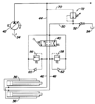
Figure 2 is a hydraulic schematic of the present inertial load hydraulic
dampening
system.
Detailed Description
Fig. 1 illustrates a backhoe 10, having a supporting frame 12 to which are
mounted
ground engaging wheels 14 for supporting and propelling the frame. Although
the current
invention is illustrated as being mounted on a wheeled work vehicle, it can
also be mounted
on a tracked work vehicle having conventional steel or rubber tracks. The
front of the
backhoe 10 is provided with a loader bucket 16 having a suitable loader bucket
linkage 17
for manipulating the loader bucket relative to the supporting frame 12. The
rear of the
supporting frame 12 is provided with a swing frame 18. A boom 20 is pivotally
coupled to
the swing frame 18, a dipperstick 22 is pivotally connected to the boom and a
bucket 26 is
pivotally connected to the dipperstick 22. A bucket actuating hydraulic
cylinder 28
manipulates the bucket 26 through a bucket linkage. The backhoe loader is also
provided
with two stabilizers 30. The operation of the vehicle is controlled from
operator's station 32.
2

CA 02323119 2000-10-13
The swing frame 18 is pivotally coupled to the vehicle frame 12 by a vertical
pivot in a
conventional manner. Hydraulic cylinders 36 pivot the swing frame 18 relative
to the
supporting frame 12 about a vertical axis defined by the vertical pivot. The
position of the
swing frame 18 relative to the supporting frame 12 is controlled by a three
position control
valve 40. The control valve 40 has a right swing position, a left swing
position, and a
stationary position. Pressurized hydraulic fluid from a source of pressurized
hydraulic fluid
42 is coupled to the control valve 40 by supply line 44. In the illustrated
embodiment the
source of pressurized hydraulic fluid is a variable displacement pump. The
control valve 40
in turn is hydraulically coupled to the hydraulic swing cylinders 3fi by first
and second work
lines 46 and 48. Pressurized and exhausted hydraulic fluid passes through the
work lines 46
and 48. Exhausted hydraulic fluid from swing cylinders 36 passes through the
control valve
40 to exhaust line 50. The exhaust line 50 is provided with a back pressure
check valve 52
which has a first pressure level. In one example the back pressure check valve
is set at 110
psi (pounds per square inch). If the pressure is less that 110 psi the valve
is closed. If the
pressure exceeds this first pressure level of 110 psi the valve opens and
hydraulic fluid is
exhausted through an oil cooler, not shown, back to tank 54 where it is
returned to the pump
42.
Each of the swing cylinders 36 are also provided with a pressure relief valve
56 and
58 and an anti-cavitation valve 60 and 62. The pressure relief valve 56 is
coupled in parallel
with anti-cavitation valve 60. Both of these valves 56 and 60 are
hydraulically positioned
between work line 46 and exhaust line 50. Similarly, the pressure relief valve
58 is coupled
in parallel with anti-cavitation valve 62. Again, both of these valves are
hydraulically
positioned between work line 48 and exhaust line 50.
The above discussed swing cylinder hydraulic configuration is typical of the
prior art
for a backhoe having a PCLS hydraulic system. The present invention is
different from the
prior art in providing a second supply line 70 and a pressure reducing valve
72. The second
supply line 70 extends between the first supply line 44 and the exhaust line
50. The flow of
pressurized hydraulic fluid through this short circuit path is controlled by
pressure reducing
valve 72 that is hydraulically positioned in the second supply line 70 and
which is set at a
second pressure level that is less than the first pressure level of the back
pressure check
valve 52. In the example discussed above the pressure reducing valve 72 is set
at 100 psi
which is 10 pounds less than the 110 psi setting of the back pressure check
valve 52. In this
way the exhaust line 50 between the back pressure check valve 52 and the
control valve 40
is maintained at a minimum pressure of 100 psi and at a maximum maintained
pressure of
3

CA 02323119 2000-10-13
110 psi. Therefore, the back pressure on the anti-cavitation valves 60 and 62
is at the same
pressure level in the exhaust line 50, and additional fluid from the exhaust
line 50 can be
supplied to the cavitating side of a hydraulic cylinder 36. By supplying the
fluid to the
cavitating side in a rapid manner the oscillation is dampened when stopping a
large body
abruptly.
The invention should not be limited to the above described embodiment, but
should
be limited solely to the claims that follow.
4

Representative Drawing
A single figure which represents the drawing illustrating the invention.
Administrative Status

For a clearer understanding of the status of the application/patent presented on this page, the site Disclaimer , as well as the definitions for Patent , Administrative Status , Maintenance Fee  and Payment History  should be consulted.

Administrative Status

Title Date
Forecasted Issue Date 2004-03-16
(22) Filed 2000-10-13
Examination Requested 2000-10-13
(41) Open to Public Inspection 2001-08-18
(45) Issued 2004-03-16
Deemed Expired 2015-10-13

Abandonment History

There is no abandonment history.

Payment History

Fee Type Anniversary Year Due Date Amount Paid Paid Date
Request for Examination $400.00 2000-10-13
Registration of a document - section 124 $100.00 2000-10-13
Application Fee $300.00 2000-10-13
Maintenance Fee - Application - New Act 2 2002-10-15 $100.00 2002-10-11
Maintenance Fee - Application - New Act 3 2003-10-14 $100.00 2003-10-10
Final Fee $300.00 2003-12-02
Maintenance Fee - Patent - New Act 4 2004-10-13 $100.00 2004-09-21
Maintenance Fee - Patent - New Act 5 2005-10-13 $200.00 2005-09-21
Maintenance Fee - Patent - New Act 6 2006-10-13 $200.00 2006-09-18
Maintenance Fee - Patent - New Act 7 2007-10-15 $200.00 2007-09-17
Maintenance Fee - Patent - New Act 8 2008-10-13 $200.00 2008-09-17
Maintenance Fee - Patent - New Act 9 2009-10-13 $200.00 2009-09-18
Maintenance Fee - Patent - New Act 10 2010-10-13 $250.00 2010-09-17
Maintenance Fee - Patent - New Act 11 2011-10-13 $250.00 2011-09-19
Maintenance Fee - Patent - New Act 12 2012-10-15 $250.00 2012-09-17
Maintenance Fee - Patent - New Act 13 2013-10-15 $250.00 2013-09-17
Owners on Record

Note: Records showing the ownership history in alphabetical order.

Current Owners on Record
DEERE & COMPANY
Past Owners on Record
GITTER, RICHARD JOHN
Past Owners that do not appear in the "Owners on Record" listing will appear in other documentation within the application.
Documents

To view selected files, please enter reCAPTCHA code :


To view images, click a link in the Document Description column. To download the documents, select one or more checkboxes in the first column and then click the "Download Selected in PDF format (Zip Archive)" or the "Download Selected as Single PDF" button.

List of published and non-published patent-specific documents on the CPD .

If you have any difficulty accessing content, you can call the Client Service Centre at 1-866-997-1936 or send them an e-mail at CIPO Client Service Centre.


Document
Description 
Date
(yyyy-mm-dd) 
Number of pages   Size of Image (KB) 
Representative Drawing 2001-08-16 1 6
Abstract 2000-10-13 1 23
Description 2000-10-13 4 198
Claims 2000-10-13 2 103
Drawings 2000-10-13 2 64
Cover Page 2001-08-16 1 38
Representative Drawing 2004-02-17 1 7
Cover Page 2004-02-17 1 39
Assignment 2000-10-13 4 140
Correspondence 2003-12-02 1 24