Note: Descriptions are shown in the official language in which they were submitted.
CA 02323351 2000-10-17
DIGIOVANIVI, D.J. 52-4-1-16 -1-
METHOD OF MAKING AN IMPROVED MULTIMODE
OPTICAL FIBER AND FIBER MADE BY METHOD
FIELD OF THE INVENTION
This invention pertains to methods of making multimode silica-based optical
fibers, and to fibers made by the method.
BACKGROUND OF THE INVENTION
Multimode (MM) silica-based optical fiber is well known. Briefly, such fiber
has a core that is contactingly surrounded by a cladding. The core has an
effective
refractive index greater than the refractive index of the cladding. The core
radius
and the refractive indices of core and cladding material are selected such
that the
optical fiber supports two or more (typically hundred or more) guided modes at
an
operating wavelength, e.g., 0.85 or 1.3p,m. Guided modes are conventionally
to designated LP~~, where the azimuthal mode number v is an integer greater
than or
equal to zero, and the radial mode number p, is an integer equal to or greater
than 1.
LPo, is the fundamental mode, and all other modes are higher order modes. The
total number N of guided modes supported by a given MM fiber is approximately
equal to V212, where V is the normalized frequency parameter (V - number) of
the
fiber.
It is well known that a MM fiber with appropriately graded core refractive
index can have substantially greater bandwidth than a similar MM fiber with
step
index profile. In particular, a conventional core refractive index profile is
expressed
by
(n(r) - n~r~r ) = 0(I _ (r I r
n(r)
where r is the radial coordinate , more is the core radius, n~~aa is the
refractive index of
the cladding adjacent to the core, D is the normalized refractive index
difference
between the center of the core and the cladding (with correction for undesired
index
dip), and a is a free parameter. For a = 2, the profile is referred to as a
parabolic
one. The optimal choice of a and 0 depend inter alia on the properties of the
CA 02323351 2000-10-17
DIGIOVANNI, D.J. 52-4-1-16 -2-
materials that make up the optically active portion of the MM fiber and on the
intended application. Frequently, a is about 2.
Efforts have been made to develop fiber index profiles that yield high
bandwidth to equalize the transit times of high order modes in a multi-mode
fiber
and to compensate for the center dip. See for instance, K. Okamoto et al.,
IEEE
Trans. Microwave Theory and Techniques, Vol. MTT-25, No. 3 (March 1977), at p.
213, and M. Geshiro et al., IEEE Trans. Microwave Theory and Techniques, Vol.
MTT-26(2), 1978, p. 115.
During the early days of optical fiber, many patents that pertain to mode
coupling in MM fibers and/or to methods of enhancing such mode coupling were
issued. For instance, US Patent No. 3,909,110 discloses step index MM fiber
waveguides with intentional fluctuations of the core refractive index. US
Patent No.
3,912,478 discloses introduction of geometrical variations into the fiber by
means of
gas streams directed against the fiber as it is being drawn. US Patent No.
3,969,016
discloses mode coupling by means of an enveloping outer jacket which is
selectively
deformed. US Patent No. 3,980,459 discloses insertion of a glass rod into the
preform during deposition of the core material, resulting in fiber having a
longitudinally eccentric index inhomogeneity. US Patent No. 3,982,916
discloses a
preform manufacturing process that involves asymmetric heating to produce
circumferentially alternating deposits of doped and undoped glass, the
resulting
fibers having longitudinal, eccentric, azimuthal index inhomogeneities.
US Patent No. 4,017,288 discloses a technique for producing optical fibers
with longitudinal variation in index of refraction. US Patent No. 4,028,081
discloses a helical optical fiber loosely confined in a protective sheath. US
Patent
No. 4,038,062 discloses a MM optical fiber with reduced modal dispersion as a
result of enhanced mode coupling, achieved by means of one or more modulated
heat sources. US Patent No. 4,049,413 discloses a method for producing optical
fibers with diameter variations in the core but with uniform overall diameter.
The
method involves etching of grooves into the preform. US Patent No. 4,093,343
3o discloses optical fiber with deliberately induced intermodal coupling, with
CA 02323351 2000-10-17
DIGIOVANNI, D.J. 52-4-1-16 -3-
longitudinally varying perturbations in the fiber. US Patent No. 4,176,911
discloses a MM optical fiber having a graded profile region followed by an
abrupt
drop in index, following by a region of constant index. At predetermined
intervals
the fiber is modified to have a conventional graded index profile.
Co-assigned U.S. patent application Serial No. 09/326,960, filed June 7,
1999 by S. E. Golowich et al for "Mufti-Mode Optical Fiber Having Improved
Refractive Index Profile and Devices Comprising Same", discloses MM fiber
having
a refractive index profile that differs from a conventional a -type profile by
at least
one of i) a step formed in the index profile at the corelcladding boundary, in
1o conjunction with a linear correction; (ii) a ripple near the core/cladding
boundary, in
combination with a linear correction, with or without an index step; and iii)
an
annular ridge formed in the index profile with a center dip.
Thus, the art knows techniques that may yield MM fiber with significant
mode coupling and thus with relatively high bandwidth. However, there is still
a
~5 need for techniques that are effective for increasing maximum bandwidth and
for
increasing the yield of fiber of average bandwidth, that are manufactureable
and can
be easily incorporated into currently used fiber manufacturing processes. This
application discloses such techniques. All herein cited references are
incorporated
herein by reference.
2o It is known from the theory of MM fibers that, if a mechanism exists that
thoroughly mixes the modes within a given mode group, and also thoroughly
mixes
the mode groups, then high bandwidth can be realized without careful grading
of the
core refractive index. See, for instance, R. Olshansky, Applied Optics, Vol.
14(4),
April 1975, p.935. All the modes of a mode group have the same propagation
25 constant (3, and different mode groups have different propagation
constants.
The above theoretical prediction has been confirmed in plastic MM optical
fibers, where high bandwidths (e.g., ~ SGHz ~ km) have been measured on fibers
with non-optimal grading of the core index.
It will be appreciated that plastic fiber inherently has severe mode mixing.
3o On the other hand, measurements of silica-based MM optical fibers show that
in
CA 02323351 2000-10-17
DIGIOVANIVI, D.J. 52-4-1-16 -4-
conventional silica-based fibers relatively little nuxing occurs within mode
groups
and between mode groups.
GLOSSARY AND DEFINITIONS
"Chirality" and related terms such as "chiral structure" are used herein in
the
conventional sense, as refernng respectively to "handedness" and "handed
structure".
"Preform" herein can refer to the preform tube before collapse as well as the
shaped or unshaped preform rod after collapse. The meaning will be clear from
the
context.
io SUMMARY OF THE INVENTION
Broadly speaking, the invention is embodied in a method of making silica-
based MM optical fiber having high bandwidth, typically greater than 100
MHz~km.
More specifically, the invention is embodied in a method of making a silica-
based MM optical fiber having a core and a cladding that contactingly
surrounds the
~5 core, the core having a radially varying refractive index. The method
comprises
providing a silica-based optical fiber preform, and drawing the optical fiber
from the
preform. Significantly, at least a portion of the preform has a non-circular
cross
section, and the drawing step comprises drawing the fiber from the preform
such
that the drawn fiber has a chiral structure. Associated with the chiral
structure
2o typically is a repeat length or period. The repeat length typically is lOcm
or less,
and typically varies along the length of the fiber.
In a preferred embodiment, the non-circular preform rod with non-circular
core is formed by collapsing the tubular preform while maintaining a reduced
pressure in the tube. In another embodiment, a non-circular core is formed by
25 selective removal of glass (e.g., by grinding or by plasma etching) from
the outside
of the preform rod, followed by fiber drawing at relatively high temperature
such
that the resulting fiber has substantially circular cross-section, but with a
non-
circular core.
In either case, a chiral structure is introduced into the fiber during
drawing,
3o generally by twisting of the fiber relative to the preform, or by twisting
of the
CA 02323351 2000-10-17
DIGIOVANNI, D.J. 52-4-1-16 -5-
preform relative to the fiber. In a preferred embodiment the fiber is twisted
alternately clockwise and counterclockwise with respect to the preform,
substantially as disclosed in US Patent No. 5,298,047.
The presence of a non-circular core, preferably together with the chirality
introduced during fiber draw, typically results in significant mode coupling
and,
consequently, in high bandwidth of the fiber, as well as in reduction of the
sensitivity of the bandwidth to the details of the index profile. In a further
exemplary embodiment of the invention the index profile differs from a
conventional parabolic or near-parabolic one, and is selected such that, in
to combination with the non-circular core and the imposed chirality, the mode
mixing
and consequent high bandwidth are increased. Exemplarily, the index profile is
as
disclosed in the above referenced 09/326,960 US patent application. The
increase in
bandwidth can be realized using either an overfilled mode launch or with a
restricted
mode launch or both.
15 The invention is also embodied in an article that comprises silica-based MM
optical fiber having non-circular cross section and chirality sufficient to
cause mode
coupling between modes in a given mode group, and between mode groups of the
MM fiber, such that the MM fiber has large bandwidth. Exemplarily, the article
is
an optical fiber communication system, e.g., an optical fiber local area
network
20 (LAN).
BRIEF DESCRIPTION OF THE DRAWINGS
FIG. 1 schematically depicts an exemplary parabolic refractive index profile;
FIG. 2 schematically shows a portion of a MM preform (or MM fiber),
indicating the radial, azimuthal and longitudinal coordinates;
25 FIG. 3 schematically shows an exemplary MM preform (or MM fiber) with
non-circular core and cladding;
FTG. 4A schematically shows an exemplary shaped MM preform, and FIG.
4B schematically shows the MM fiber drawn from the shaped preform at
relatively
high temperature; and
CA 02323351 2000-10-17
DIGIOVANNI, D.J. 52-4-1-16 -6-
FIG. 5 schematically depicts an exemplary optical fiber communication
system comprising MM fiber according to the invention.
FIGs. 6-9 show pulse amplitude as a function of time, for various offsets, for
multimode fiber produced under various conditions, with and without vacuum
collapse, and with and without twisting;
FIGs. 10-13 show pulse center differential mode dispersion and pulse width,
as a function of lateral offset, for the multimode fibers of FIGs. 6-9,
respectively;
and
FIG. 14 schematically depicts a further exemplary embodiment of fiber
1o according to the invention.
The figures that depict objects are not intended to be to scale or in
proportion.
DETAILED DESCRIPTION
FIG. 1 shows an exemplary MM fiber refractive index profile with a-type
core index. In FIG. l, n is the refractive index, r is the radial coordinate,
11 is the
core refractive index n(r), 12 is the cladding refractive index n~,aaa,~g ,and
13 is the
core/cladding interface. Silica-based optical fiber typically is contactingly
surrounded by a polymer cladding. Such a cladding does not play a role in this
application and will not be discussed further.
2o It will be appreciated that conventional MM transmission fibers have a
structure that is essentially independent of the azimuthal and the
longitudinal fiber
coordinate, with any departure from azimuthal and/or longitudinal constancy
being
an undesirable manufacturing defect. However, optical fibers that have
longitudinally varying structure are known, as are optical fibers that exhibit
azimuthal variation. For an example of the former see for instance, U.S.
Patent
5,298,047 which discloses introduction of a permanent spin into the fiber for
reduction of polarization mode dispersion. An example of the latter is
polarization-
maintaining fiber. See, for instance, D.N. Payne et al., IEEE Journal of
Quantum
Electronics, Vol. QE-18(4), April 1982, p. 477.
3o Both types of fibers generally are single mode fibers.
CA 02323351 2000-10-17
DIGIOVArTNI, D.J. 52-4-1-16 -7-
An important feature of the method according to this invention is the
introduction of perturbations into the MM optical fibers, such that
substantial mode
mixing occurs during operation of the fiber, i.e., during transmission of
electromagnetic radiation of an operating wavelength ~,. The mode mixing
desirably
comprises mixing the modes within a given mode group, as well as mixing of the
mode groups. By way of example, fluctuations of the core diameter as a
function of
the longitudinal coordinate tend to produce mode coupling within mode groups,
and
nacrobends in the fiber tend to produce mode coupling between mode groups. For
a
discussion of mode coupling in MM optical fibers see, for instance, R.
Olshansky,
1o Reviews of Modern Physics, Vol. 51 (2), pp. 341-367 (1979).
FIG. 2 schematically shows a prior art MM preform or optical fiber, with
numerals 21-25 referring, respectively, to the core, the cladding, the radial
coordinate, the azimuthal coordinate and the longitudinal coordinate.
The goal of achieving high bandwidth through mode mixing in silica-based
~5 MM fibers can be achieved by introduction , in any appropriate manner, of
suitable
perturbations into the optical fiber. However, many of the known techniques
for
making MM fibers with mode-coupling perturbations are difficult to carry out
in a
manufacturing environment, and/or are difficult to incorporate into currently
used
fiber manufacturing processes. Thus, a method of introducing perturbations
into
20 MM fiber that can be carried out in a manufacturing environment and can be
easily
incorporated into a conventional process for making MM fiber is needed, and is
disclosed herein.
Suitable ways of introducing such perturbations are a) carrying out the
preform collapse while maintaining a reduced pressure (e.g., 0.1 atmospheres
or
25 less) in the interior of the preform tube, such that the collapsing preform
assumes a
non-circular cross section, followed by imposition of chirality on the fiber
during
drawing from the preform; and b) removing glass from the outside of a
conventional
preform rod such that the resulting shaped preform has non-circular (e.g.,
polygonal)
cross section. Fiber is then drawn from the shaped preform, with the drawing
3o temperature being sufficiently high such that the outside of the fiber
becomes
CA 02323351 2000-10-17
DIGIOVANNI, D.J. 52-4-1-16 -8-
substantially circular and the core becomes non-circular. During drawing of
the
fiber from the preform, chirality is imposed on the fiber.
FIG. 3 schematically depicts a collapsed non-circular optical fiber preform
(or fiber drawn from the collapsed preform), with numerals 31 and 32 referring
to
the core material and the cladding material. The preform typically is produced
by
MCVD in conventional fashion. After deposition of the core material (and
typically
of some cladding material) the tubular preforTn of circular cross section is
collapsed
into a solid glass rod. During the collapse, conditions are selected such that
at least
part of the tubular body assumes non-circular shape. Typically this is
achieved by
t0 maintaining a reduced pressure inside the tubular preform, at least for a
portion of
the collapse time. Subsequent to completion of the collapse the resulting
glass body
is mounted in a draw tower and fiber is drawn. The fiber is twisted relative
to the
preform, or the preform is twisted relative to the fiber, such that the
resulting optical
fiber has chiral structure, typically with azimuthal and radial perturbations
along the
15 longitudinal axis of the fiber.
A further exemplary technique for making MM fibers with non-circular core
cross section comprises making a conventional MM preform and collapsing the
preform in conventional fashion. The resulting circularly symmetric glass rod
is
then shaped such that the rod no longer has circular symmetry. For instance,
the rod
20 can be shaped by grinding or by means of a plasma torch to have polygonal
(e.g.
hexagonal) cross section, or to have substantially oval cross section. FIG. 4A
schematically shows a portion of a preform with substantially oval cross
section.
Numerals 41 and 42 refer to the (circularly symmetric) core and the cladding,
respectively.
25 After completion of the shaping operation the shaped preform is mounted in
a draw tower and optical fiber is drawn from the preform. The temperature of
the
hot zone will typically be relatively high (e.g., in the range 2100-
2400°C), selected
such that the outside of the fiber assumes substantially circular shape (due
to surface
tension) and the core consequently becomes non-circular. This is shown in FIG.
4B,
30 wherein numerals 411 and 422 refer to the noncircular core and the
substantially
CA 02323351 2000-10-17
DIGIOVAN1VI, D.J. 52-4-1-16 -9-
circular cladding, respectively. Not only is the fiber drawn at relatively
high
temperature but chirality is imposed on the fiber during fiber drawing. This
exemplatily is done by twisting the fiber relative to the preform, or by
twisting the
preform relative to the fiber. The resulting fiber typically has azimuthal and
radial
perturbations along the longitudinal coordinate of the fiber.
The imposition of chirality on the fiber can be achieved in any appropriate
way. For instance, the preform in the draw furnace can be spun around on its
axis.
See, for instance, U.S. Patent No. 4,504,300. In a currently preferred
embodiment
the fiber is alternately twisted clockwise and counterclockwise. See U.S.
Patent No.
5,298,047, which shows, inter alia, a draw tower that can alternately twist
the fiber
clockwise and counterclockwise by means of an oscillating guide roller. The
alternating twist modulates the repeat length which typically yields enhanced
mode
mixing.
MM fiber according to the invention advantageously is used in a high speed
optical fiber communication system, exemplarily a LAN. FIG. 5 schematically
shows an exemplary optical fiber communication system 50 comprising a
transmitter 51, a receiver 52, and MM optical fiber 53 signal-transmissively
connecting transmitter and receiver.
Example
2o A conventional tubular multimode preform was formed and divided into two
parts before collapse. One of the two parts was collapsed in conventional
fashion,
the other was collapsed under vacuum. From each of the two collapsed preforms
was drawn a length of fiber without twisting, as well as a similar length with
twisting. Differential mode delay measurements were then carried out on 300m
lengths of the respective fibers. The vacuum collapse and subsequent fiber
drawing
resulted in core orality of 13.9%, whereas the core ovality was 4.6% without
vacuum collapse. The draw speed and twisting were selected to result in 30
twists/m.
CA 02323351 2000-10-17
DIGIOVA1VNI, D.J. 52-4-1-16 -t0-
FIGs. 6-9 respectively pertain to fiber without vacuum collapse and without
twisting, to fiber without vacuum collapse and with twisting, to fiber with
vacuum
collapse and without twisting, and to fiber with vacuum collapse and with
twisting.
The figures show pulse amplitude as a function of time, for various offsets of
the launched pulses. Each figure shows pulse amplitudes for 9 offsets (0, ~
5~m, ~
l0~tm, ~ 15~m, and ~ 20~tm, from bottom to top). For purposes of the instant
qualitative discussion it is not necessary to identify the pulses with
corresponding
positive and negative offsets. Inspection of FIGS. 6-9 shows that the pulses
of FIG.
9 (vacuum collapsed, twisted during drawing) have substantially smaller pulse
width
1o than the pulses of the other figures, indicative of greater bandwidth of
the vacuum
collapsed and twisted MM fiber. The pulses of FIG. 9 also have considerably
less
structure than the pulses of FIGs. 6-8, also indicative of higher bandwidth.
Furthermore, the relatively structure-free zero-offset pulse of FIG. 9
indicates a
reduced effect of the (generally present) central index dip.
FIGS. 10-13 show corresponding data on pulse center differential mode
dispersion (reference numerals 101, 111, 121 and 131, respectively) and pulse
width
(reference numerals 102, 112, 122 and 132, respectively), as a function of
lateral
offset. The pulse width data pertains to the right hand ordinate (in ps), and
pulse
center relative delay pertains to the left hand ordinate (in ps/m).
2o Inspection of FIGs. 10-13 shows that the vacuum collapsed twisted fiber
(FIG. 13) has lower pulse width and lower differential mode dispersion than
the
other fibers, indicative of larger bandwidth for the vacuum collapsed and
twisted
fiber.
In a further exemplary embodiment of the invention the preform is made
such that the core has circular circumference but has an index profile that
increases
in ovality from the circumference (where it typically is zero) to the center
of the
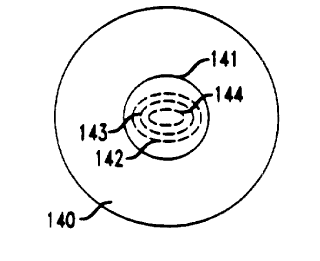
core. This is illustrated in FIG. 14, wherein reference numerals 140 and 141
refer,
respectively, to the cladding and the circumference of the core, and numerals
142-
144 refer to lines of equal refractive index. A preform according to FIG. 14
is
exemplary of a preform that is made such that at least a portion of the
preform has
t CA 02323351 2000-10-17
DIGIOVANTTI, D.J. 52-4-1-16 -tt-
non-circular form. It will be understood that FIG. 14 also represents fiber
drawn
from the preform, the core of the fiber having non-circular cross-section.
A figure of merit (FOM) was defined as follows: Consider all of the pulses
measured on the 300m length of MM fiber. Tabulate the arrival time of the
leading
and trailing edges of the pulses at the half maximum power point. Calculate
the
maximum difference in time between the earliest arrival time of the leading
edges
and the latest arrival time of the trailing edges. This parameter is
designated T",~.
The FOM is then defined as FOM=T",~/P, where P=2/3 times the bit period. In
the
instant example, P=67ps.
to FOM =1 means that the total span of the pulses fits into 2/3 of the bit
period,
and FOM =10 means that the total span of the pulses is 10 times the width of
the bit
period. A small FOM is generally associated with large bandwidth.
The FOM for the four above-discussed MM fibers was determined, and
found to decrease from no vacuum collapse/no twisting (FOM=7.0) to no vacuum
collapse/twisting (FOM=5.4) to vacuum collapse/no twisting (FOM=4.8) to vacuum
collapse/twisting (FOM=2.7).
It will be understood that the above described procedures and results are
exemplary, and that practice of the invention does not require that various
fiber
types are formed from the same tubular preform.