Note: Descriptions are shown in the official language in which they were submitted.
CA 02323455 2000-09-11
WO 99/45989 PCT/US99/05325
METHOD AND APPARATUS FOR PROVIDING
POSITIVE AIRWAY PRESSURE TO A PATIENT
CROSS REFERENCE TO RELATED APPLICATIONS
This is a continuation-in-part of application
Serial No. 08/679,898 filed June 15, 1996, which is a
continuation-in-part of application Serial No. 08/253,496
filed June 3, 1994, now U.S. Patent No. 5,535,738.
BACKGROUND OF THE INVENTION
1. Field of the Invention
The present invention relates generally to methods
and apparatus for treating breathing and/or cardiac
disorders and, more particularly, to methods and apparatus
for providing a pressure to an airway of a patient during at
least a portion of the breathing cycle to treat obstructive
sleep apnea syndrome, chronic obstructive pulmonary disease,
congestive heart failure, and other respiratory and/or
breathing disorders.
2. Description of the Related Art
During obstructive sleep apnea syndrome (OSAS),
the airway is prone to narrowing and/or collapse while the
patient sleeps. Continuous positive airway pressure (CPAP)
therapy seeks to avoid this narrowing by supplying pressure
to splint the airway open. With CPAP, this splinting
pressure is constant and is optimized during a sleep study
to be sufficient in magnitude to prevent narrowing of the
SUBSTIME SHEET (RULE 26)
CA 02323455 2000-09-11
WO 99/45989 PCT/US99105325
airway. Providing a constant splinting pressure, i.e.,
CPAP, is a simple solution to the problem posed by the
collapsing airway. However, this approach exposes the
patient to pressures that are higher than the pressures
S needed to support the airway for most of the breathing
cycle.
During inspiration, the pressure created within
the lungs is lower than the pressure at the nose. This
pressure difference drives the flow of air into the lungs.
This pressure difference creates a pressure gradient in the
airway connecting the lungs with the nose. That is to say,
the nose is typically at ambient pressure while the lungs
and airway of the patient are at sub-ambient or negative
pressures. This negative pressure acts upon the airway and
contributes to its collapse. CPAP levels are typically set
to raise the pressure level in the entire respiratory system
to the level required to both eliminate the sub-ambient
pressures generated by inspiration and overcome any
mechanical collapsing forces that result from the structure
of the airway tissues, muscle tone, and body position. The
inspiratory pressures , i.e., inspiratory positive airway
pressure or "IPAP," in bi-level positive airway pressure
systems are set in a similar manner.
During exhalation, a positive pressure gradient
exists between the interior of the lungs and the exterior of
the body. This positive pressure gradient helps to support
the airway during exhalation. At the end of exhalation, the
pressure gradient is essentially zero; flow is likewise zero
and the airway is unaffected by respiratory efforts. Any
collapse of the airway at the end of exhalation is purely a
function of the structure of the airway tissues, muscle
tone, and body position. Bi-level devices seek to supply
the expiratory pressure required to support the airway at
the end of exhalation.
-2-
SUBSTITUTE SHEET (RULE 26)
CA 02323455 2000-09-11
WO 99/45989 PCT/US99/05325
It should be noted that over the course of a
breathing cycle, the pressure gradients between the lungs
and the exterior of the body are not constant. The
inspiratory pressure gradient falls from zero at the start
of inspiration to a peak negative value and then rises back
to zero at the end of inspiration. The expiratory pressure
gradient rises from zero at the start of exhalation to a
peak value and then falls back to zero as exhalation ends.
Because the pressure gradient varies over the breathing
cycle, the pressure necessary to overcome airway collapse
should ideally vary over the breathing cycle.
Traditional CPAP therapy ignores these variations
in pressure requirements and provides therapy at one
pressure level. Conventional CPAP is rather crude and
offers far from optimal therapy since the CPAP pressure is
based solely on a worst-case treatment parameter, i.e., the
peak pressure requirements during inspiration.
Representing an advancement over conventional
CPAP, bi-level positive airway pressure (bi-level PAP)
therapies seek to take advantage of the different pressure
requirements to lower the pressure during exhalation.
Nevertheless, bi-level therapies also fail to afford optimal
treatment because the inspiratory positive airway pressure
(IPAP) of bi-level PAP is again based on the patient's peak
needs encountered during inspiration and remains constant
over the entire inspiratory phase respiration. Also, during
bi-level treatment, the expiratory position airway pressure
(EPAP) remains constant and is related solely to the support
needs at the end of exhalation.
In addition to OSAS, positive airway pressure
therapy, such as bi-level PAP therapy, has been applied in
the treatment of other breathing disorders, such as chronic
obstructive pulmonary disorder (COPD). One of the problems
with this mode of treatment, however, is that the patient
has difficulty stopping inspiratory flow. This phenomenon
-3-
suBS~ur~ sH~r (~u~ 2s~
CA 02323455 2000-09-11
WO 99/45989 PCT/US99/05325
arises due to the disparity between applied IPAP and the
pressure needed to overcome the patient's respiratory
resistance at the end of inspiration. As the former
pressure typically exceeds the latter, the "surplus" IPAP at
the end of inspiration leads to uncomfortable and
potentially harmful hyperinflation of the patient lungs.
Conversely, in order to begin inspiratory flow, a
COPD patient must reduce the pressure inside his lungs to a
pressure that is less than the ambient pressure at the inlet
of his respiratory system. Due to the condition commonly
known as "Auto-PEEP," the pressure in the patient's lungs is
typically above ambient pressure at the end of exhalation.
The patient's breathing muscles thus must perform additional
work to expand the lungs and thereby reduce lung pressure
below ambient before flow into the lungs can occur. Auto-
PEEP is typically treated with a form of resistive counter
pressure known as PEEP (positive end expiratory pressure).
PEEP is set at a level just below the patient's Auto-PEEP
level, thereby reducing the amount of breathing work
required to initiate inspiratory flow.
With conventional treatments, such as pressure
support, CPAP or bi-level therapy, PEEP is achieved by
applying the same pressure over the entire phase of
expiration, e.g., the EPAP phase of bi-level PAP therapy.
It should be noted that EPAP is not synonymous with PEEP.
EPAP indicates a constant pressure delivered to the patient
throughout exhalation, while PEEP indicates positive end
expiratory pressure. By definition, the PEEP pressure is
only required at the end of exhalation. As such, the
administration of EPAP throughout the expiratory cycle to
assure that satisfactory PEEP is maintained undesirably
contributes to the breathing work that a patient must
perform during exhalation.
In addition to CPAP and bi-level PAP, other
systems have been proposed for clinical research and/or
-4-
SUBSTIME SHEET (RULE 26)
CA 02323455 2000-09-11
WO 99/45989 PCT/US99/05325
therapeutic application, including treatment of OSAS, COPD
and other breathing disorders, that offer an assortment of
methods and apparatus by means of which a subject's
respiratory efforts may be induced, superseded, assisted
S and/or resisted. Some of these systems perform their
prescribed functions responsive to one or more parameters
associated with a subject's respiratory activity including,
but not limited to, inspiratory and/or expiratory flow,
inspiratory and/or expiratory pressure, tidal volume and
symptoms indicative of airway obstruction, e.g., snoring
sounds. Some achieve their objectives transthoracically
while others deliver air at positive or negative pressure
directly to the subject's airway.
An early example of such a system, commonly
referred to as an "iron lung," is disclosed in a publication
entitled "Mechanical Assistance to Respiration in Emphysema,
Results with a Patient-Controlled Servorespirator," authored
by James R. Harries, M.D. and John M. Tyler, M.D., published
in the American Journal of Medicine, Vol. 36, pp. 68-78,
January 1964. The iron lung proposed in that publication is
a respirator designed to apply and remove transthoracic
pressure to and from the exterior surface of the body of a
subject who sits in a large pressurizable chamber in order
to assist the patient's respiratory efforts (i.e., the iron
lung applies negative pressure during inspiration and either
ambient or positive pressure during expiration).
Sophisticated for its day, the apparatus continually
controlled the internal chamber pressure in response to the
patient's spontaneous respiration, specifically in response
to detected respiratory flow or volume. Indeed, a signal
obtained from a strain gauge pneumograph fastened around the
patient's chest was electrically separated into three
components: one proportional to volume, another to
inspiratory flow and a third to expiratory flow. Each
3$ component was assigned a separate gain control. The
-5-
SUBSTIME SHEET (RULE 26)
CA 02323455 2000-09-11
WO 99!45989 PC'T/US99/05325
component signals are then recombined to control the
pressure in the chamber by means of an electrically driven
variable valve situated between a blower and the chamber.
Although effective for their intended purposes,
this and other iron lung devices have generally fallen into
disfavor because of their bulk, inconvenience, cost and
limited application. That is to say, because of their size
and cost such equipment is purchased and maintained
essentially exclusively by medical facilities such as
hospitals and clinics. Further, iron lungs do not lend
themselves to treatment of OSAS and related disorders where
comfort and unobtrusiveness are critical for patient
compliance and treatment efficacy. This is because negative
pressure applied during inspiration compounds the factors
that operate to collapse the airway during an inspiratory
phase.
An essay entitled, "An Apparatus for Altering the
Mechanical Load of the Respiratory System," authored by
M. Younes, D. Bilan, D. Jung and H. Krokes, and published in
1987 by the American Physiological Society, pp. 2491-2499,
discloses a system for loading and unloading of a subject's
respiratory efforts to effect various respiratory responses.
The system may load or unload during inspiration,
expiration, or both, to assist or resist a subject's
spontaneous respiratory activity. The system may apply a
continuous positive or negative pressure directly to the
subject's airway and loading or unloading occurs via a
command signal generated by detected respiratory flow,
volume, applied voltage, an external function, or other
source .
A drawback to this system, however, is that a
single resistive gain is chosen for resistive loading or
unloading. This single gain is applied to a "half-wave" of
the respiratory cycle (e;ther inspiration or expiration) or
the "full-wave" thereof (both inspiration and expiration).
-6-
SUBSTITUTE SHEET (RULE 26)
CA 02323455 2000-09-11
WO 99/45989 PCT/US99/05325
In other words, under full-wave respiratory loading or
unloading, a single chosen gain value is employed during
both inspiration and expiration. Thus, a gain that may
produce favorable results in regard to reducing breathing
work during inspiration, for example, may cause less than
desirable or even detrimental consequences during
expiration. The converse is true for a gain selected
specifically for optimizing expiratory work reduction.
In addition, the Younes et al. system operates as
a closed, leak-proof system. Hence, to predict its ability
to function in an open, leak-tolerant system would be
problematic. As such, whether it may be adapted to OSAS
treatment, which invariably involves some degree of known
and unavoidable unknown system leakage, is suspect.
U.S. Patent No. 5,107,830 to Younes essentially
reiterates all of the "breathing assist" (unloading)
disclosure that is covered in the Younes, et al. American
Physiological Society publication discussed above. In the
system disclosed in U.S. Patent No. 5,107,830, however, the
adjustable pressure gain is only realized during inspiration
because pressure output is set to zero during exhalation.
Additionally, output pressure is calculated as a function of
both detected patient inspiratory flow and volume.
Furthermore, the system is applicable to COPD but not OSAS
therapy.
An article entitled "A Device to Provide
Respiratory-Mechanical Unloading," authored by Chi-sang Poon
and Susan A. Ward and published in March 1987,in IEEE
Transactions on Biomedical Engineering, Vol. BME-33, No. 3,
pp. 361-365, is directed to an apparatus which functions
somewhat similar to one mode of operation described in both
Younes disclosures. That is, the Poon, et al. device may
operate to unload a subject's breathing, but only during
inspiration. Poon, et al. provide their inspiratory
assistance by establishing a positive mouth pressure
_7_
SUBSTITUTE SHEET (RULE 26)
CA 02323455 2000-09-11
WO 99/459$9 PCT/US99/05325
throughout inspiration in a constant proportion to
instantaneous flow. The constant proportion is achieved by
(1) selecting a desired gain for a detected positive mouth
pressure signal, (2) calculating the ratio of the
gain-modified mouth pressure signal over a detected signal
reflecting instantaneous flow, (3) comparing the calculated
ratio to a selected reference ratio to generate a valve
motor control signal, and (4) using the valve motor control
signal to operate a motor that drives « servo valve to
control the positive pressure applied to the subject's
airway. Thus, the apparatus output pressure is determined
as a function of both detected pressure and flow. Further,
the pressure must be output at a value sufficient to
maintain a constant ratio of pressure to flow.
A publication entitled "Servo Respirator
Constructed from a Positive-Pressure Ventilator," by John E.
Remmers and Henry Gautier, which was published in August,
1976 in the Journal of Applied Physiology, Vol. 41, No. 2,
pp. 252-255, describes a modified ventilator that may
function as a "demand" respirator generating a transthoracic
pressure proportional to phrenic efferent respiratory
discharge. Phrenic efferent respiratory discharge is an
indication of the outgoing brain signal to the phrenic
nerve, which controls diaphragm function. A phrenic
efferent respiratory discharge signal causes the diaphragm
to contract whereby the subject exerts an inspiratory
effort. The phrenic efferent respiratory discharge serves
as the apparatus command signal and is processed to produce
a moving time average (MTA) and the subject's tracheal
pressure serves as a negative feedback signal. Like the
Poon et al. device, the Remmers et al. apparatus provides
respiratory assistance only during inspiration.
An apparatus for automatically regulating the flow
and pressure output of a respirator is disclosed in U.S.
Patent No. 3,961,627 to Ernst et al. Like the
_g_
suBSmu~ sH~r (uu~ 2s~
CA 02323455 2000-09-11
WO 99/45989 PCT/US99/05325
aforementioned Poon et al. device, however, the Ernst et al.
apparatus relies upon an unduly complicated scheme dependent
upon detected respiratory pressure and flow in calculating
delivered output flow and pressure. More particularly,
S Ernst et al. propose regulating the delivered flow and
pressure of a respiration gas in a respirator during the
respiration cycle in which the actual flow and pressure of
the respiration gas are measured via a measuring device
arranged proximate a patient interface. The measured values
are converted into electrical signals and the flow and
pressure of the respiration gas are controlled during the
inspiration and expiration portions of the respiration cycle
via a valve arranged between a respiration gas source and
the measuring device. The method for regulating the flow
and pressure output comprises (1) measuring the actual flow
of respiration gas proximate the patient, (2) measuring the
actual pressure of respiration gas proximate the patient,
(3) calculating nominal values of flow and pressure from
preselected fixed values and the actual values, (4)
comparing the actual values measured for the flow and
pressure with the nominal values, and (5) obtaining from the
comparison a control signal for modulating the valve and
thereby regulating the flow and pressure of the respiration
gas.
?5 Additionally, apart from its utilization of two
detected respiratory parameters (flow and pressure) and the
complex manner in which these and other variables are
reiteratively processed to produce apparatus flow and
pressure output, the Ernst et al. system, although capable
of delivering a base pressure equivalent to a patient's
required end expiratory pressure, is nevertheless unable to
deliver any pressure less than the base pressure.
Consequently, the Ernst et al. apparatus requires the
patient to perform more breathing work than is necessary to
satisfy his respiratory needs, especially in the expiratory
_4_
SUBSTITUTE SHEET (RULE 26)
CA 02323455 2000-09-11
WO 99/45989 PCT/US99/05325
phase of a respiration cycle, thereby deleteriously
affecting the patient's comfort and likelihood of continued
compliance with the treatment.
In addition to the treatment of breathing
disorders, positive airway pressure therapy has been applied
to the treatment of congestive heart failure (CHF). In
using CPAP on CHF, the effect of the CPAP is to raise the
pressure in the chest cavity surrounding the heart. This
has the impact of reducing the amount of pressure the heart
has to pump against to move blood into the body. Hy
reducing the pressure the heart works against, the work
required of the heart is reduced. This allows the sick
heart to rest and potentially to get better.
The pressure in the chest cavity is also impacted
by respiration effort. With inspiration, the pressure in
the chest is reduced (negative relative to resting pressure)
due to inspiratory effort. This forces the heart to pump
harder to move blood into the body. With expiration, the
pressure in the chest is slightly increased (positive
relative to resting pressure) due to the elastic properties
of the chest. This allows the heart to decrease its efforts
to pump blood. While conventional CPAP can help the heart
rest, it has negative aspects for the patient such as
increased work of exhalation and discomfort from the
pressure.
SUMMARY OF THE INVENTION
It is an object of the present invention to
provide an uncomplicated system operable to deliver
pressurized air to the airway of a patient and readily
adaptable to the treatment of OSAS, COPD and other
respiratory and/or pulmonary disorders that does not suffer
from the disadvantages of conventional pressure application
-10-
SUBSTIME SHEET (RULE 26)
CA 02323455 2000-09-11
WO 99/45989 PCT/US99/05325
techniques. This object is achieved by providing an
apparatus for delivering pressurized breathing gas to an
airway of a patient. The apparatus, which is referred to
below as a "proportional positive airway pressure" or "PPAP"
apparatus, includes a gas flow generator, a patient
interface that couples the gas flow generator to the
patient's airway, a sensor that detects a fluid
characteristic associated with a flow of gas within the
patient interface, a pressure controller that regulates the
pressure of breathing gas provided to the patient, and a
control unit that controls the pressure controller.
The control unit controls the pressure controller
so that the breathing gas is delivered to the patient at a
minimally sufficient pressure during at least a portion of a
breathing cycle to perform at least one of the following
functions at any given moment: (1) reduce cardiac preload
and afterload, in which case the minimally sufficient
pressure is a summation of a pressure needed to reduce
cardiac preload and afterload in an absence of respiratory
loading and a pressure needed to overcome an impact of
respiratory loading on cardiac preload and afterload, and
(2) prevent airway collapse, in which case the minimally
sufficient pressure is a summation of a pressure needed to
prevent airway collapse and a pressure needed to overcome
respiratory effort. The apparatus also includes a selector
unit that establishes a first gain. The control unit
controls the pressure controller so as to deliver the
breathing gas at the minimally sufficient pressure during at
least a portion of the breathing cycle based on the first
gain and the signal from the sensor.
The PPAP system of the present invention provides
airway pressure that is lower than pressures typically
necessary to treat OSAS, which is normally treated using
conventional CPAP or bi-level PAP therapy. With PPAP, the
patient receives exhalation pressures lower than
-11-
SUBSTITUTE SHEET (RULE 26)
CA 02323455 2000-09-11
WO 99/45989 PCT/US99105325
conventional bi-level PAP expiratory positive airway
pressure levels and well below conventional CPAP levels.
Also, the average pressure delivered during inspiration can
be lower than conventional or bi-level PAP inspiratory
positive airway pressure or CPAP levels, whereas peak PPAP
pressure is roughly equivalent to conventional IPAP or CPAP
levels. The PPAP pressure range (peak inspiratory pressure
to minimum expiratory pressure) is generally between 2 to 20
cm H20, with typical values in the 8 to 14 cm H20 range.
This is consistent with bi-level PAP therapy where
significant comfort/compliance is found with peak
inspiratory to minimum expiratory pressure differentials of
6 cm HZO or more. The complexity of titration using the
apparatus of the instant invention is roughly equivalent to
current bi-level PAP titration. In addition, the titration
system may incorporate a feedback circuit to provide fully
automated PPAP.
Similar to treatment of OSAS, PPAP also delivers
mean airway pressure that is lower than pressures typically
necessary to treat COPD using conventional bi-level PAP
therapy with PEEP or proportional assist ventilation (PAV)
with PEEP. That is, with PPAP, the patient receives average
exhalation pressures lower than conventional EPAP levels,
average inspiration pressures lower than conventional IPAP,
and peak PPAP pressure roughly equivalent to conventional
IPAP pressures and conventional peak PAV levels. Hence,
less breathing work is required with PPAP than with
conventional PAV or bi-level treatments of COPD or OSAS.
It is a further object of the present invention to
provide a modified CPAP apparatus that is capable of easily
detecting exhalation and modifying the exhalation pressure
to match a selected pressure profile. This object is
achieved by providing an apparatus that includes a gas flow
generator, a patient interface that couples the gas flow
generator to the patient's airway, a sensor that detects a
-12-
SUBSTITUTE SHEET (RULE 26)
CA 02323455 2000-09-11
WO 99/45989 PCT/US99/05325
physiological condition that is suitable for use to
differentiate between an expiratory phase and an inspiratory
phase of a breathing cycle, a pressure controller that
regulates the pressure of breathing gas provided to the
patient, and a control unit that controls the pressure
controller. More specifically, the control unit causes the
breathing gas to be delivered at a first pressure level
during an inspiratory phase of the breathing cycle, which
is consistent with the operation of a conventional CPAP
device. However, the control unit causes the breathing gas
to be delivered in accordance with a predetermined pressure
profile during the expiratory phase of the breathing cycle.
This profile provides a decrease in the EPAP provided to the
patient. Because the pressure profile can be obtained by
controlling the operation of existing CPAP devices, it can
be readily implemented on many such devices, thereby
providing a better therapy for a patient using existing
devices.
It is yet another object of the present invention
to provide a system for eliminating oscillations in the flow
provided during patient exhalation that can occur with use
of the PPAP device. According to a first embodiment of the
present invention, this object is achieved by causing the
pressure controller to provide a pressure to the patient
during expiration that is the greater of (1? a first
minimally sufficient pressure that is determined by applying
a gain to the signal output by the sensor and (2) a second
minimally sufficient pressure that corresponds to a current
pressure being provided to the patient. By ensuring that
the pressure provided to the patient is always the greater
of these two pressures, the pressure received by the patient
during expiration does not oscillate, because should the
pressure to be provided to the patient begin to decrease
below the current pressure, the device will not use the
calculated pressure, but will continue to provide the
-13-
SUBSTIME SHEET (RULE 26)
CA 02323455 2000-09-11
WO 99/45989 PCT/US99/05325
patient with the current pressure, thereby preventing a
pressure decrease below the current pressure.
According to a second embodiment of the present
invention, the object of preventing oscillations in the
patient flow provided during expiration is achieved by
causing the pressure controller to provide an expiration
pressure that is determined based on a volume of gas to be
exhaled and a gain. This gain can be the same gain or a
different gain from that applied to the signal from the
sensor during inspiration (if any). The volume of gas to be
exhaled corresponds to a difference between the current
volume of gas in the patient and the volume of gas in the
patient at rest.
These and other objects, features and
characteristics of the present invention, as well as the
methods of operation and functions of the related elements
of structure and the combination of parts and economies of
manufacture, will become more apparent upon consideration of
the following description and the appended claims with
reference to the accompanying drawings, all of which form a
part of this specification, wherein like reference numerals
designate corresponding parts in the various figures. It is
to be expressly understood, however, that the drawings are
for the purpose of illustration and description only and are
not intended as a definition of the limits of the invention.
BRIEF DESCRIPTION OF THE DRAWINGS
Figure 1 is a functional block diagram of an
apparatus according to the instant invention;
Figure 2 is a functional block diagram of a
further embodiment of an apparatus according to the instant
invention;
-14-
suesmurs sH~ tuu~ 2s~
CA 02323455 2000-09-11
WO 99/45989 PCTNS99/05325
Figures 3A and 3B are flow and pressure diagrams,
respectively, graphically representing the general manner in
which an apparatus according to the instant invention
outputs pressurized breathing gas in a proportional relation
to the patient flow in both the inspiratory and expiratory
phases of a single respiratory cycle;
Figures 4A and 4B are flow and pressure diagrams,
respectively, similar to Figures 3A and 3B, exemplifying a
number of apparatus output pressure curves that are achieved
through selective adjustment of inspiratory and expiratory
gain setting controls of the proportional positive airway
pressure circuitry of the instant invention;
Figures 5A and 5B are flow and pressure diagrams,
respectively, similar to Figures 3A and 3B, contrasting a
pressure output curve typical of an apparatus according to
the instant invention with pressure output curves of a
conventional respiratory assistance apparatus;
Figures 6A and 6B are flow and pressure diagrams,
respectively, similar to Figures 3A and 3B, depicting
alternative pressure profiles that are employed at the
beginning of an inspiratory phase of respiration to
facilitate the onset of inspiration;
Figures 7A and 7B are flow and pressure diagrams,
respectively, similar to Figures 3A and 3B, illustrating a
resultant apparatus pressure output curve according to a
further embodiment of the present invention;
Figures 8A and 8B are flow and pressure diagrams,
respectively, similar to Figures 3A and 3B, showing a
resultant apparatus pressure output curve achieved by
combing a conventional bi-level positive airway pressure
therapy with the proportional positive airway pressure
therapy according to the instant invention;
Figures 9A and 9B are flow and pressure diagrams,
respectively, similar to Figures 3A and 3B, reflecting a
further resultant apparatus pressure output curve achieved
-15-
SUBSTITUTE SHEEP (RULE 26)
CA 02323455 2000-09-11
WO 99/45989 PCT/US99/05325
by combining a conventional bi-level positive airway
pressure therapy with proportional positive airway pressure
therapy according to the instant invention;
Figure 10 is a functional block diagram of a
further embodiment of an apparatus according to the instant
invention
Figures 11A and 11B are flow and pressure
diagrams, respectively, similar to Figures 7A and 7B,
illustrating a resultant apparatus pressure output curve
according to a further embodiment of the present invention
that utilizes a simplified pressure profile generating
technique;
Figure 12 is a pressure diagram illustrating the
occurrence of oscillations in the pressure provided to the
patient during exhalation;
Figure 13 is a pressure diagram illustrating a
first technique for reducing the oscillations illustrated in
Figure 12; and
Figure 14 is a pressure diagram illustrating a
second technique for reducing the oscillations illustrated
in Fig. 12.
DETAILED DESCRIPTION OF THE
PRESENTLY PREFERRED EMBODIMENTS
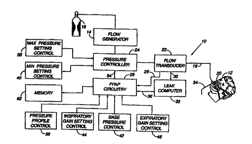
There is generally indicated at 10 in Figure 1 a
proportional positive airway pressure apparatus according to
a presently preferred embodiment of the instant invention
and shown in the form of a functional block diagram.
Apparatus 10 is operable according to a novel process to
deliver breathing gas, such as air, oxygen or a mixture
thereof, at relatively higher and lower pressures (i.e.,
generally equal to or above ambient atmospheric pressure) to
-16-
SUBSTITUTE SHEET (RULE 26)
CA 02323455 2000-09-11
WO 99/45989 PCT/US99/05325
a patient 12 in proportion to the patient's respiratory flow
for treatment of OSAS, COPD and other respiratory disorders.
Apparatus 10 includes a gas flow generator 14,
such as a conventional CPAP or bi-level PAP blower, i.e., a
S centrifugal blower with a relatively steep pressure-flow
relationship at any constant speed, that receives breathing
gas from any suitable source, e.g., a pressurized bottle 16
of oxygen or air, the ambient atmosphere, or a combination
thereof. The gas flow from flow generator 14 is passed via
a delivery conduit 18 to a breathing appliance or patient
interface 20 of any suitable known construction that is worn
by patient 12. In an exemplary embodiment of the present
invention, the conduit 18 is a large bore flexible tube and
the patient interface 20 is either a nasal mask or a full
face mask, as shown. Other breathing appliances that may be
used in lieu of a mask include a mouthpiece, a nasal seal,
nasal prongs or cannulae, an endotracheal tube, a trachea
adapter or any other suitable appliance for interfacing
between a source of breathing gas and a patient. Also, the
phrase "patient interface" can encompass more that the
interface worn by the patient. For example, the patient
interface can include delivery conduit 18 and any other
structures that connect the source of pressurized breathing
gas to the patient.
The apparatus also includes a sensor, such as a
flow transducer 22 or similar flow sensing element, situated
within or near the breathing circuit, i.e., the patient
interface 20, conduit 18 or gas flow generator 14. Flow
transducer 22 may be any suitable gas flow meter, such as,
for example, a bidirectional dynamic mass flow sensor.
Preferably, however, the flow transducer is a pressure
responsive sensor for detecting the magnitude of the
pressure gradients between the inlet of the patient's airway
and his lungs. Within the scope of the present invention,
-17-
SUBSTIME SHEET (RULE 2fi)
CA 02323455 2000-09-11
WO 99/45989 PCT/US99/05325
flow and respiratory pressure gradient are highly
correlated.
In accordance with a presently preferred
embodiment, the flow transducer 22 is interposed in line
with conduit means 18, most preferably downstream of a
pressure controller 24. The flow transducer generates
output signals that are provided, as indicated by reference
numeral 26, to PPAP circuitry 28 described in greater detail
hereinafter. The output signals include first flow rate
signals indicative of inspiration by the patient and second
flow rate signals indicative of the patient's expiration.
The signals are continuously transmitted and correspond to
the instantaneous flow rate of breathing gas within conduct
means 18.
In addition, the output from flow transducer 22 is
also desirably provided, as indicated by reference numeral
30, to an optional leak detecting system 32. A suitable
leak detector for present purposes is that disclosed in LT. S.
Patent No. 5,148,802, the disclosure of which is
incorporated herein by reference. However, other techniques
for substantially instantaneously calculating system
leakage, including both known leakage, such as that
discharged through a mask exhaust port 34, and unknown
leakage, such as that at various conduit couplings or at the
patient contact site of the patient interface 20, are
acceptable. With any non-invasive embodiment of the present
invention, i.e., not involving an endotracheal tube or
trachea adapter, the patient flow must be estimated taking
into account the aforesaid known and unknown system leaks.
The output signal from the leak detecting system
32 is provided, as at 36, to PPAP circuitry 28. In this
way, the PPAP circuitry logic continuously compares the
output from flow transducer 22 with that from leak detecting
system 32 to discriminate that portion of system flow
associated with the patient's respiration from that caused
-18-
SUBSTIME SHEET (RUlF 26)
CA 02323455 2000-09-11
WO 99/45989 PCT/US99/05325
by system leakage. As a result, PPAP circuitry 28 more
precisely controls the output of the pressure controller 24
as a function of patient respiratory flow, rather than
overall system flow.
If formed as a mask, as illustrated, patient
interface 20 commonly includes, as mentioned above, a
suitable exhaust system, schematically indicated at 34, to
exhaust breathing gases during expiration. Exhaust system
34 preferably is a continuously open port that imposes a
suitable flow resistance upon exhaust gas flow to permit
pressure controller 24, located in line with conduit 18
between flow generator 14 and patient interface 20, to
control the pressure of air flow within the conduit and thus
within the airway of the patient. For example, exhaust port
34 may be of sufficient cross-sectional flow area to sustain
a continuous exhaust flow of approximately 15 liters per
minute at a system pressure of 10 cm HZO. The flow via
exhaust port 34 is one component, and, typically, the major
component of the overall system leakage, which is an
important parameter of system operation. In an alternative
embodiment, it has been found that a non-rebreathing valve
may be substituted for the continuously open port.
Pressure controller 24 controls the pressure of
breathing gas within conduit 18 and thus within the airway
of the patient. Pressure controller 24 is located
preferably, although not necessarily, downstream of flow
generator 14 and may take the form of an adjustable,
electronically-controlled valve.
Apparatus 10 also desirably includes a safety
circuit, preferably comprising an adjustable maximum
pressure setting control 38 and an adjustable minimum
pressure setting control 40 operatively connected to
pressure controller 24. The safety circuit allows the
manufacturer, the patient or his overseeing health care
professional to selectively establish minimum and maximum
-19-
SUBSTITUTE SHEET (RULE 26)
CA 02323455 2000-09-11
WO 99/45989 PCT/US99/05325
system output pressures below and above which the system
will not dispense pressurized gas. The minimum pressure
will, of course, be at least zero and, preferably, a
threshold pressure sufficient to maintain pharyngeal patency
during expiration. The maximum pressure, on the other hand,
will be a pressure somewhat less than that which would
result in over-inflation and perhaps rupture of the
patient's lungs. The safety circuit functions differently
than the pressure controls which determine, for instance,
the CPAP prescription pressure or the IPAP and EPAP
prescription pressures used in bi-level PAP therapy. That
is, instead of establishing lower and upper prescription
pressures to be administered during normal usage of the
apparatus (subject to the influence of the PPAP circuitry
28), the maximum and minimum pressure setting controls 38
and 40 set absolute minimum and maximum fail-safe output
pressure limits which are not to be exceeded. Thus, the
danger of potential physical harm to the patient in the even
of malfunction of other system components, e.g., the
prescription pressure controls, is effectively eliminated.
PPAP circuitry 28, according to the present
invention, is subject to the influence of additional
essential controls, including a base pressure control 42, an
inspiratory gain setting control 44, and an expiratory gain
setting control 46. The base pressure control 42
establishes a base pressure (Pbase), usually greater than or
equal to zero and conceptually equal to the EPAP level in
bi-level therapy, sufficient to maintain airway patency at
the beginning and end of exhalation. The inspiratory gain
setting control 44 permits selection of a resistive gain
(Gainin.p) to be applied to the detected inspiratory flow.
Similarly, the expiratory gain setting control 46 enables
selection of a resistive gain (Gaininsp) to be applied to the
detected expiratory flow.
-20-
SUBSTITUTE SHEET (RULE 26)
CA 02323455 2000-09-11
WO 99/45989 PCT/US99/05325
In a broad sense, PPAP therapy and the PPAP
apparatus to constitute a novel system providing pressure to
a patient via nasal, nasal/oral, oral, or trachea interface
to treat OSAS, COPD and other breathing disorders. The
pressure delivered to the patient is a function of the
patient flow rate. The function can be described as
follows:
Pdelivered = Pbase + Gain * Flow
where:
"Pdelivered" is the pressure delivered to the
patient interface;
"Pbase" is the base line pressure (greater than or
equal to zero and conceptually equal to EPAP);
"Flow" is the estimated patient flow rate
determined by the flow transducer; and
"Gain" is the constant used to augment pressure
based on the flow rate. The gain constant can further be
refined to allow one constant for inspiration (positive
flow) and a different constant for exhalation (negative
flow) .
Figures 3A and 3B represent flow and pressure
diagrams, respectively, graphically depicting the manner in
which apparatus 10 outputs pressurized breathing gas in
proportional relation to patient flow, as detected by flow
transducer 22, in both the inspiratory and expiratory phases
of a respiratory cycle. The pressure curve of Figure 3B
reflects a situation where the same gain is chosen for both
inspiratory and expiratory flow. Conceivably, essentially
the same pressure curve may be generated by the apparatus
disclosed in the aforementioned essay entitled "An Apparatus
for Altering the Mechanical Load of the Respiratory System,"
-21-
SUBSTIME SHEET (RULE 26)
CA 02323455 2000-09-11
WO 99/45989 PCT/US99/05325
by Younes, et al. which may use a single resistive gain
applicable to both inspiration and expiration.
With PPAP apparatus 10, however, separate and
independent gains may be chosen for inspiration and
expiration, whereby gains best suited to optimizing
performance, i.e., minimizing breathing work, may be
precisely matched with each of the inspiratory and
expiratory phases. Thus, the function of the apparatus
described in the Younes et al. article.corresponds to a
special and relatively limited application of the present
invention where the selected inspiratory and expiratory
gains are identical.
As is far more often the case, however, an optimum
inspiratory gain is not the optimum expiratory gain and vice
versa. Thus, the pressure output of the PPAP apparatus 10
is more accurately described according to the following
functions, which functions can be encoded into the PPAP
circuitry 28.
Pinhalation = Pbase + Gainin,p * Flow
and
Pexhalation = Pbase + Gains * Flow
Where:
"Gaini",p" is the constant used during inspiration
(positive flow) to boost pressure based on the flow rate;
and
"Gain" is the constant used during exhalation
(negative flow) to reduce pressure based on the flow rate.
The gain typically selected has a range of about 0
to 10 cm H~0/liter/second for inspiration. The gain chosen
for exhalation is normally lower than the inspiratory gain,
-22-
sues sH~r tsu~ 2s~
CA 02323455 2000-09-11
WO 99/45989 PCT/US99/05325
e.g., values in the range of 0 to 4 cm H~O/liter/second,
although higher gain values may be chosen for inspiration
and/or expiration, if such is desired or necessary.
Regardless of the chosen gain values, applying a
flow signal derived from a normal respiratory pattern will
result in a pressure rise above Pbase during inspiration and
will drop below Pbase during exhalation. When patient flow
is near zero, i.e., at the beginning and end of inspiration,
as well as the beginning and end of exhalation, the output
pressure approaches Pbase.
Figures 4A and 4B perhaps most clearly exemplify
the effect that the selection of different gains for both
the inspiratory and expiratory phases of a respiratory cycle
has upon the pressure output curve . Galni"eP~a~ , Galninap(b)
Gaininsp,~, and GainIneP~a~ represent, in descending order,
several of an infinite range of gain values that may be
applied during inspiration. Similarly, Gaine,~~~~ , GainE,~~f~ ,
GainE,~~g~ and GainB,~~h~ indicate increasing expiratory gain
values. With different gain settings, any number of wave
forms can be generated. For example, a high setting may be
established for Gaininap and a low setting for GainE,~, or
vice versa, or the gain settings for inspiratory flow and
expiratory flow may be the same.
In one embodiment of the present invention, PPAP
therapy seeks to provide only the pressure that is necessary
to prevent airway collapse at any given moment during the
breathing cycle. This will generally result in supplying,
at appropriate times, maximum pressure only when peak
negative airway inspiratory pressures are detected and
minimum pressure only when peak positive airway exhalation
pressures are detected. At all other times during the
breathing cycle, the PPAP apparatus delivers air at a
variable pressure responsive to the patient's respiratory
efforts in a range between the maximum and minimum
pressures. As mentioned above, PPAP therapy also involves
-23-
SUBSTITUTE SHEET (RULE 26)
CA 02323455 2000-09-11
WO 99/459$9 PCTNS99/05325
the administration of a base pressure of zero or greater to
which the product of a selected gain times instantaneous
flow (inspiratory and expiratory) is continuously added to
produce the instantaneous output pressure of the PPAP
apparatus,. An identical gain may be selected for
inspiration and expiration, or different gain values may be
independently selected for inspiration and expiration. The
base pressure will be the pressure necessary to overcome any
mechanical collapsing forces that result from the structure
of the airway tissues, muscle tone, and body position. In
other words, the base pressure is generally equivalent to
the expiratory positive airway pressure or "EPAP" typically
used in bi-level PPAP therapy.
In this connection, Figures 5B illustrates the
pressure output curve generated by the PPAP apparatus 10
vis-a-vis conventional CPAP and bi-level PAP apparatus over
a single respiratory cycle. So long as the appropriate
inspiratory and expiratory splint pressures are applied at
point 48 (peak inspiratory flow), point 50 (beginning of
exhalation) and point 52 tend of exhalation), less pressure
may be provided at all other times during the breathing
cycle than is normally supplied by conventional CPAP or
bi-level PAP therapy. This reduced output pressure is
represented by the "PPAP" curve of Figure 5B. The hatched
areas of that figure reflect the difference in pressures
provided by PPAP and the IPAP and EPAP phases of bi-level
PAP during a typical respiratory cycle. The hatched areas
may be conceptualized as the respiratory work or effort
savings that are attributed to PPAP. This work savings, as
would be expected, translates to greater comfort for the
PPAP assisted patient and increased compliance with the
respiratory treatment. According to the present invention,
PPAP therapy thus represents a novel respiratory disorder
treatment by which patient comfort (and, therefore,
-24-
SUBSTIME SHEET (RULE 26)
CA 02323455 2000-09-11
WO 99/45989 PCTNS99/05325
treatment compliance) exceed that offered by either CPAP or
bi-level PAP therapy.
Referring again to Figure 1, it will thus be
appreciated that pressure controller 24 is continuously
governed by and outputs variable pressure responsive to a
command signals 54 from PPAP circuitry 28. Command signals
54, in turn, are the product of the influences of one or
more of the outputs from flow transducer 22, leak detection
system 32, base pressure control 42, inspiratory gain
setting control 44, expiratory gain setting control and, in
an alternative embodiment, a pressure profile control 56
discussed below.
In normal breathing, a negative pressure gradient
must be generated bef ore flow can begin. Hence, the
negative pressure waveform generated in the airway must
precede and thereby induce inspiratory flow at the start of
inspiration. In an unstable airway, which is characteristic
of OSAS, for example, this asynchronous relationship of
negative pressure gradient and inspiratory flow onset would,
if not accommodated by suitable compensatory measures, lead
to a situation where the PPAP therapy would not generate
sufficient pressure (due to low flow) to overcome the
negative pressure in the airway, whereby total or partial
airway collapse may result. This problem can be solved by a
number of methods. For instance, a higher PPAP base
pressure can be used to provide additional pressure to
support the airway at the beginning of inspiration.
Alternatively, however, as demonstrated by Figures 6A and
6B, a temporary pressure increase can be added at the start
of inspiration to support to the airway until sufficient
flow is generated to drive the PPAP process. The present
invention offers several viable approaches by means of which
pressure can be added during the initial phase of
inspiration to support the airway as inspiratory flow
increases.
-25-
SUBST~UT~ SHEET (RULE 26)
CA 02323455 2000-09-11
WO 99/45989 PCTNS99/05325
Temporary pressure increases may be effected using
pressure profile control 56 in operative connection with
PPAP circuitry 28 to select a desired elevated pressure
waveform in the early stages of inspiration. In this
regard, pressure profiles may be used as minimum values for
the output pressure at the outset of inspiration, thereby
giving rise to the following alternative equations for
available output pressure during inspiration.
Pinhalation = greater of:
Pbase + Gaininsp * Flow
or
Pbase + Pprofile
where:
"Pinhalation" is the pressure delivered to the
patient interface during inspiration "Pbase" is the base
line pressure (conceptually equal to EPAP);
"Flow" is the estimated patient flow;
"Galninsp" is the constant used during inspiration
(positive flow) to boost pressure based on the flow rate;
and
"Pprofile" is a function that generates a pressure
profile to support the airway at the start of inspiration.
Such pressure profile functions may be constant, e.g., a
step profile as shown by the dotted line identified by
numeral 58 in Figure 6B, time based (for instance, a
backwards ramp profile as shown by the dotted and dashed
line identified by numeral 60 in Figure 6B), or any other
functional shape.
-26-
SUSSTIME SHEET (RULE 26)
CA 02323455 2000-09-11
WO 99/45989 PCT/US99/05325
Alternatively, pressure profiles can be used
exclusively to control the output pressure for a
predetermined initial segment of inspiration. The following
equations represent system output pressure during
S inspiration under such control conditions.
Pinhalation = Pprofile from start of breath to X
and
Pinhalation = Pbase + GainInaP * Flow from X to
start of exhalation
where
"Pinhalation" is the pressure delivered to the
patient interface during inspiration;
"Pbase" is the base line pressure (conceptually
equal to EPAP);
"Flow" is the estimated patient flow;
"GainInBp" is the constant used during inspiration
(positive flow) to boost pressure based on the flow rate;
and
"Pprof ile" is any function that generates a
?5 pressure profile to support the airway at the start of
inspiration. Such functions could be constant, such as, for
example, a step profile, or time based, such as a backwards
ramp profile, or any other functional shape.
"X" is a preselected transition point determined
by time, or analysis of the flow signal, such as curvature,
percent drop from peak flow rate, integration, derivative,
analysis of prior breaths or a combination of flow analysis
and time.
The PPAP apparatus 10 also has the capacity to
measure and store in a memory 62 (Figure 1) the following
-27-
SUBSTfME SHEET (RULE 26)
CA 02323455 2000-09-11
WO 99/45989 PCT/US99/05325
parameters: tidal volume, inspiratory time, expiratory
time, peak pressure, peak flow, Oz saturation (as a voltage
input from an external source?, plural pressure !as a
voltage input from an outside source), mask pressure,
estimated leakage, and system parameters, e.g., Pbase, Auto
Galninsp, GalnInBp, GainEBp, IPAP and EPAP. It is to be
understood that this list is not exclusive; other parameters
can be stored in memory 62.
A further method by which the present system
addresses the problem presented by the changing needs of the
patient is to combine the beneficial features of PPAP with a
more controlled therapy such as CPAP, as is shown in Figures
7A and 7B.
With CPAP, a single pressure is generated and
delivered throughout the sleeping session. PPAP can be
advantageously joined with CPAP to lower the pressure
provided to the patient during exhalation. The resulting
equations for pressure delivered under combined PPAP-CPAP
are as follows:
Pinhalation = CPAP
and
Pexhalation = CPAP + GainE,~ * Flow
where:
"Gain" is the constant used during exhalation
(negative flow) to reduce pressure based on the flow rate.
Figures 8A and 8B demonstrate that PPAP can also
be combined with bi-level PAP therapy in a number of ways to
produce effective therapeutic pressure waveforms. One
application, generally similar to the aforementioned PPAP-
CPAP scenario, is to use PPAP to lower the pressure during
-28-
SUBSTIME SHEET (RUL~ 26)
CA 02323455 2000-09-11
WO 99/45989 PCT/US99/05325
exhalation. The resulting equations for the delivery of
composite PPAP - bi-level PAP pressure are as follows:
Pinhalation = IPAP
and
Pexhalation = EPAP + GainE,~, * Flow
where:
"GainE,~" is the constant used during exhalation
(negative flow) to reduce pressure based on the flow rate.
Another approach to merging PPAP with bi-level
therapy is shown in Figures 9A and9B where IPAP is applied
to the patient for a first portion of the inspiratory cycle
and PPAP is applied for the remainder of the breathing
cycle. GaininsP is automatically calculated for each breath
based on IPAP and the flow rate as follows:
Pinhalation (to to tl) - IPAP
and
Pinhalation (tl to t~) - Pbase + AutoGain=n,p * Flow
and
Pexhalation = Pbase + GainE,~ * Flow
where:
"Flow" is the estimated flow rate;
"to" is the time at the start of breath;
-29-
SUBSTIME SHEET (RULE 26)
CA 02323455 2000-09-11
WO 99/45989 PCTNS99/05325
"tl" is the time when the estimated flow rate is a
predetermined percentage of peak inspiratory flow rate;
"t~" is the time at the start of exhalation;
"IPAP" is a continuously applied inspiratory
positive airway pressure;
"Pinhalation (to to tl)" is the pressure delivered
to the patent from to to t,;
"Pbase" is a continuous base pressure;
"AutoGainin,p" equals (IPAP-Pbase) /Flow at t,;
"Pinhalation (tl to t2)" is the pressure delivered
to the patient from t, to t2;
"GainE,~" is the constant used during exhalation to
reduce pressure delivered to the patient; and
"Pexhalation" is the pressure delivered to the
patient during exhalation.
It is to be understood that the flow and PPAP
pressure output curves of Figures 3A through 9B represent
the apparatus output pressure and flow during the
inspiratory and expiratory phases of a single respiratory
cycle. The PPAP and flow curves can, of course, be expected
to vary somewhat from respiratory cycle to respiratory cycle
depending on the patient's respiratory requirements,
particularly under fully automated PPAP therapy described
hereinafter. Furthermore, somewhat greater variations will
likely occur between the respiratory cycles associated with
different stages of an extended treatment session,
especially during OSAS treatment.
Figure 2 represents a further preferred embodiment
of a PPAP apparatus pursuant to the present invention,
designated herein by reference numeral 10'. Apart from the
addition IPAP/EPAP (bi-level PPAP) circuitry 64, PPAP
apparatus 10' is identical in structure and function to PPAP
apparatus 10. According to this embodiment, output 66 from
flow transducer 22 is fed to bi-level PAP circuitry 64. Bi-
level PAP circuitry 64 may assume any conventional form such
-30-
SUBSTIME SHEET (RULE 26)
CA 02323455 2000-09-11
WO 99/45989 PCT/US99/05325
as, for example, that described in U.S. Patent Nos.
5,148,802; 5,433,193; and 5,632,269, the contents or which
are incorporated herein by reference. Output 68 from bi-
level PPAP circuitry 64 is transmitted to the PPAP circuitry
28. Output 68 consists of an IPAP signal if the patient is
inhaling and an EPAP signal in the event the patient is
exhaling. The logic of the PPAP circuitry 28 utilizes this
input according to a preselected one any of the
aforementioned combinations of PPAP-bi-level therapy to
generate a desired pressure command signal 54.
Pursuant to the present invention, the pressure
delivered to the patient is determined by the base pressure,
the flow rate and the gain (and the pressure profile if
used). For a given patient condition, these settings can be
adjusted as necessary to stabilize the airway. In OSAS, a
patient's periodic and, to a lesser extent, instantaneous
condition is variable with sleep state and body position.
Thus, settings that may work well in during one portion of a
sleeping session may not work as well at a different time.
In other words, settings that support the airway at its most
unstable state may cause pressures that are higher than
necessary during more stable times. Likewise, settings that
work well at one point in the session may be insufficient at
another time.
The present invention proposes several methods to
minimize the impact of the patient's changing needs on the
optimization of PPAP therapy. One such method is to
automatically adjust the gain, pressure profile and baseline
pressure to meet the patient's demands. This adjustment can
be based on analysis of patient parameters related to flow,
e.g., magnitude, shape, derivative, integral (volume),
pressure , snoring, arterial oxygen saturation, exhaled CO~,
airway diameter, or other parameters.
Using one or more of these parameters the system
may adjust the GainineP to prevent partial airway obstruction
-31-
SUBSTITUTE SHEET (AUK 26)
CA 02323455 2000-09-11
WO 99/45989 PCT/US99/05325
(hypopnea). The goal of such systems is to increase Gaininep
responsive to any of the following patient conditions:
° decreased inspiratory flow;
° decreased inspiratory volume;
° increased airway resistance, as determined by flow or
pressure signal analysis;
° airway instability, as indicated by pressure or sound
variations;
° drops in arterial oxygen saturation; or
° decreases in airway diameter.
The apparatus according to the invention may also
maintain minimal Gainin6p in the absence of these conditions.
The present system may also adjust the base
pressure (Pbase) to prevent complete collapse of the airway
(apnea) or severe collapse (severe hypopnea). Apnea can be
detected by analysis of the flow signal and/or by using
reflected pressure waves, or a combination of pressure and
flow to determine airway patency. Moreover, it may be
important to determine if the apnea is caused by airway
collapse or by a lack of respiratory drive. If an
obstructive event is detected the base pressure can
therefore be increased to open the airway. A further
capability of the present system is to maintain a minimum
Pbase in the absence of these conditions.
The system may also adjust the pressure profile
(Pprofile) to prevent apnea or hypopnea at the onset of
inspiration. As such, the system may increase Pprofile in
response to decreased inspiratory flow, decreased
respiratory volume, flow waveform shape analysis that
indicates increasing airway resistance, pressure or sound
variations indicative of airway instability, drops in
arterial oxygen saturation, decreases in airway diameter or
a change in exhaled COz. Commensurate, therewith, the
-32-
SUBSTIME SHEET (RULE 26)
CA 02323455 2000-09-11
WO 99/45989 PCT/US99/05325
present invention also functions to maintain the minimum
pressure profile in the absence of these conditions.
Figure 10 reveals a presently preferred embodiment
of a fully automated PPAP apparatus 10" constructed
according to the present invention. Generally similar in
structure and function to PPAP apparatus 10 of Figure 1,
PPAP apparatus 10" additionally incorporates a
microprocesser or central processing unit (CPU) 70 that
preferably utilizes an output signal 72 from flow transducer
28 as a continuous feedback signal to enable the CPU to
continuously adjust Pbase, Pprofile, Gainln,p, and Gains as
necessary. The CPU may, however, be configured to effect
its continuous system control functions responsive to any of
the aforementioned patient parameters related or unrelated
to respiratory flow.
Apparatus 10" also has the capability to detect
hypopnea, as evidenced by decreases in peak flow and/or
tidal volume for a given period of time, and the occurrence
of apneas, as manifested by very little flow for a given
period of time. To detect hypopnea, for example, the CPU 70
may be programmed to make a comparison between a short term
average of peak inspiratory flow rate or tidal volume (e. g.,
a 3 breath average) and a long term average of peak flow
rate or tidal volume (e.g., greater than 20 breaths). If a
decrease of greater than 25% is detected the system
determines a hypopnea to be present. This determination is
desirably made only if the leakage is well estimated and
stable. Thus, large changes in leak or initiation of a leak
recovery will cause data to be ignored.
The invention further includes a method for
determining if the airway is open (central apnea) or
obstructed (obstructive apnea) during an apnea. Once an
apnea of significant duration is detected the system, under
the direction of CPU 70, automatically increases Gain~n,P by
2 cm H20, waits approximately 1 second and decreases the
-33-
SUBSTfME SHEET (RULE 26)
CA 02323455 2000-09-11
WO 99/45989 PCT/US99/05325
pressure back to the original value. If there is a
significant change in flow during this pressure change, the
system concludes that the airway is open (central apnea).
If there is no significant change in flow the system
determines that the airway is obstructed (obstructive
apnea). The system will continue to monitor each apnea for
its entire duration at periodic intervals to determine the
nature of the apnea.
In accordance with a preferred embodiment, the
PPAP apparatus 10" controls are automatically adjusted as
follows. In the event of a hypopnea, Gaini"sP is increased
by 2 cm/liter/second. In the event of an obstructive apnea,
Pbase is increased by 1 cm H20. The device will continue to
increase Pbase as long as an obstructive apnea of
significant duration is detected. The device will not
increase Gainlngp again, if necessary, until 5 breaths have
passed. If no hypopnea or apneas occur over a period of 30
breaths, Gainl"sp is decreased by 1 cm/liter/second. If no
hypopnea or apneas occur over a period of 50 breaths, Pbase
is decreased by 1 cm HZO. In addition, the apparatus may
control the delivery of OZwhile patient flow is greater
than zero, if such desired or necessary.
Although not illustrated, still further
embodiments of the present invention contemplate the
incorporation of fully automated PPAP with CPAP and/or bi-
level PAP therapy. In these cases CPAP or IPAP may be
controlled using the same logic that controls Gainln.p in the
above-described fully automated PPAP system. Likewise,
Pbase may be controlled in a similar manner to that
described in connection with fully automated PPAP.
The fully automated PPAP-CPAP or PPAP-bi-level PAP
systems may also adjust Pprofile to prevent apnea or
hypopnea at the start of inspiration. Such systems may
therefore increase CPAP (or IPAP) or Pprofile in the face
any of the following patient conditions:
-34-
SUBSTIME SHEET (RULE 26)
CA 02323455 2000-09-11
WO 99/45989 PCTNS99105325
° decreased inspiratory flow;
° decreased inspiratory volume;
° increased airway resistance, as determined by flow or
pressure signal analysis;
° airway instability, as indicated by pressure or sound
variations;
° drot~s in arterial oxygen saturation; and
° decreases in airway diameter.
It will be understood that CPAP or IPAP would be
maintained at minimal levels in the absence of these
conditions.
Using PPAP therapy, therefore, it is additionally
possible to employ PPAP in response to expiratory flow to
reduce pressure applied during expiration to less than the
patient's PEEP level throughout all but the end of the
expiratory phase in a manner similar to that described for
lowering the pressure below Pbase during exhalation in the
treatment of OSAS. This lowering of applied pressure to
less than PEEP during the expiratory phase diminishes
breathing work and enhances patient comfort when compared to
the constant expiratory phase pressure applied during EPAP.
Indeed, PPAP can be adapted to any ventilation mode that
uses PEEP. Such applications may include pressure support
with PEEP, PAV with PEEP or other applications of PEEP in
respiratory assistance therapy.
Furthermore, the administration of oxygen in phase
with inspiration may also easily be included with PPAP
therapy for the treatment of COPD patients requiring
supplemental oxygen.
The present invention also contemplates that the
pressure of the gas being provided to the patient can be
controlled so as to vary over time. For example, in one
embodiment of the present invention, the pressure provided
-35-
SUBSTfME SHEET (RULE 26)
CA 02323455 2000-09-11
WO 99/45989 PCT/US99/05325
to the patient increases from a first minimum pressure to a
desired therapy pressure over a period of time. This ramp
increase in pressure provides the patient with time to fall
asleep under relatively low pressure that is increased to
the therapy pressure over time. Thereafter, the pressure
increases so that the therapy pressure is being applied
after the patient is asleep. A reverse process can be
performed in the morning, with the pressure being decreased
from the therapy pressure shortly bef ore the patient intends
to wake up. Ramp control 120 in Figure 10 schematically
illustrates a manually actuated controller that provides
commands to PPAP circuitry 28 to cause the pressure to be
provided according to a ramp cycle. Furthermore, the ramp
control may be adjusted according to the output of CPU 70.
Ramp control 120 can be used to set the parameters
associated with the ramp function, such as the ramp period,
ramp start time, ramp stop time, and ramp shape.
Examples of techniques for controlling the
pressure level provided to the patient via one or more ramp
functions, as well as other methods for controlling the
patient pressure, are disclosed in U.S. Patent Nos.
5,492,114; 5,551,418 and RE 35,295, the contents of each are
incorporated herein by reference. Many of the techniques
taught by these patents can be incorporated into the present
apparatus and method to provide the optimum therapy
necessary to treat the patient.
In a still further embodiment of the present
invention, an alarm 122 is coupled to PPAP circuitry 28
and/or CPU 70. Alarm 122 can be controlled so as to be
actuated as a result of a variety of circumstances.
However, in a preferred embodiment of the invention, alarm
122 is actuated responsive to an automatically determined
gain falling outside a predetermined range of values.
The present invention also contemplates limiting a
value for an automatically determined gain, such as
-36-
SUBSTIME SHEEP (RULE 26)
CA 02323455 2000-09-11
WO 99/45989 PCT/US99/05325
AutoGainInsp discussed above, to prevent the automatically
determined gain from exceeding predetermined limits, for
example, from exceeding limits that may result in an
excessively high pressure being provided to the patient.
The limits on the amount that the gain can themselves be
altered so that these limits vary over a predetermined
period of time. Also, the amount of change that may take
place in the automatically determined gain aver a
predetermined period of time can also be controlled, thereby
preventing the automatically determined gain from changing
by more than a predetermined amount over the predetermined
period of time.
In using PPAP to treat CHF, the present invention
reduces mean pressure and work of exhalation while still
providing the same level of rest to the heart. By applying
a positive base pressure substantially equivalent to a
pressure needed to reduce cardiac preload and afterload
(preferably in the range of 5-10 cm Hz0), the present
invention helps the heart reduce its efforts. With
additional positive pressure during inspiration in
proportion to respiratory effort, one can overcome the
effect of negative pressure being produced during
inspiration. PPAP is particularly appropriate in CHF
patients in that the typical CHF patient has normal lung
'S compliance. In these patients, much of the respiratory
loading can be inferred from the flow signal. By reducing
the pressure below the base pressure during exhalation, one
can reduce the work of exhalation without, reducing the
benefit to the heart. The net effect will be the same
benefit to the heart with reduced work of breathing and
lower mean pressure.
Similar to PPAP therapy's use for preventing
airway collapse, PPAP therapy for the treatment of CHF
delivers only the minimum amount of pressure needed to
reduce cardiac preload and afterload. This will result in
-37-
SUBST(ME SHEET (RULE 26)
CA 02323455 2000-09-11
WO 99/45989 PCTNS99/05325
supplying a base pressure to the exterior of the heart
equivalent to the pressure needed to reduce cardiac preload
and afterload in the absence of respiratory loading and a
varying pressure which is needed to overcome the impact of
respiratory loading on cardiac preload and afterload while
minimizing the work of breathing.
Supplying positive pressure to the exterior of the
heart via the respiratory system has two benefits firstly,
the positive pressure will reduce the enlarged heart of a
CHF patient to a size closer to normal. This return to
normal size, allows the muscles of the heart to work more
effectively. Secondarily, the positive pressure in the
chest cavity reduces the amount of pressure the heart must
overcome to pump blood to the rest of the body.
The heart and chest cavity are at the same
pressure. Typically this pressure fluctuates about ambient
pressure due to the impact of respiratory loading. The
circulatory system has a working pressure that varies as the
heart pumps but averages 100 mm HG in normal-tensive
patients. The heart must supply the power to force blood
from the chest cavity into the pressurized circulatory
system. Increasing the pressure in the chest cavity reduces
the amount of pressure the heart must over come to pump
blood. A pressure in the chest cavity of 10 cm H~O or
approximately 10 mm Hg will reduce the load on the heart by
10 mm Hg/100 mm Hg or roughly 10%.
The impact of respiratory effort on the heart is
as follows: during inspiration, the pressure in the chest
(and thus surrounding the heart) becomes more negative
relative to the rest of the body. This increased negative
pressure increases the amount of pressure the heart must
generate to pump blood from the chest cavity to the body.
By providing pressure in excess of the base pressure during
inspiration, PPAP is able to offset this decrease in chest
-38-
SUBSTIME SHEEP (RULE 26)
CA 02323455 2000-09-11
WO 99/45989 PCT/US99/05325
cavity pressure and maintain a relatively constant pressure
in the chest.
During exhalation the pressure in the chest
becomes less negative relative to the rest of the body. By
S reducing the pressure during exhalation, PPAP is able to
offset the increase in chest cavity pressure and maintain a
relatively constant pressure in the chest.
By minimizing the decrease in pressure and taking
advantage of the increased pressure during exhalation, the
variable portion of PPAP allows a lower baseline to be set
relative to using a constant pressure with the same benefits
to the heart. This lower baseline and reduced pressure
during exhalation also reduces the work of breathing and
increases patient comfort.
It is further desirable to implement a version of
PPAP similar to that discussed above with respect to Figure
7 on existing CPAP devices. Providing a version of PPAP on
existing CPAP devices enhances the patient comfort and,
hence, compliance without the significant financial and
other burdens appurtenant to manufacturing and introducing a
new CPAP device that includes a PPAP mode. Providing a PPAP
therapy on a CPAP device can be accomplished in a variety of
ways, such as that discussed above with respect to Figures
7A and 7B.
A version of PPAP can be implemented on a CPAP
system in a more cost effective manner if the reactive
component used to generate the reduced pressure curve during
exhalation in Figure 7 is replaced with a defined reduced
pressure profile. This pressure profile replaces the
constant CPAP pressure otherwise applied by the CPAP device
during the expiratory phase of the patient's breathing
cycle. In an preferred embodiment of the present invention,
the defined pressure profile has a shape that generally
corresponds to a patient's normal flow.
-39-
SUBSTITUTE SHEET (RULE 26)
CA 02323455 2000-09-11
WO 99/45989 PCTNS99/05325
Figures 11A and 11B are flow and pressure diagrams
similar to Figures 7A and 7B illustrating a resultant
apparatus pressure output curve according to a further
embodiment of the present invention that utilizes a
simplified pressure profile generating technique. Flow
signal 80 in Figure 11A illustrates the patient's
inspiratory phase 82 and expiratory phase 84. As shown in
Figure 11B, a continuous CPAP pressure 86 is delivered
during the inspiratory phase 82. During the expiratory
phase, the pressure support device is controlled to deliver
a reduced pressure following a predetermined pressure
profile 88. The resulting equations for pressure delivered
under the combined CPAP and PPAP are as follows:
Pinhalation = CPAP
and
Pexhalation = CPAP - Predetermined Pressure
profile.
The predetermined pressure profile, which is used
to reduce the CPAP pressure, has a magnitude M, which is
typically selected by a respiratory therapist in a range of
0-4cmH20, and a duration D that, unlike the pressure curve
in Figure 7B, is not directly determined base on the
patient's instantaneous flow or volume. The magnitude M
represents the drop in pressure from the constant CPAP
value. The duration D value is preferably a fraction of an
average expiration period of the patient.
Multiple predefined pressure profiles, having
different magnitudes, durations or both can be stored in a
CPAP/PPAP device and provided to the patient. Figure 118
illustrates three predetermined pressure profiles P1, P2 and
-40-
SUBST(ME SHEET (RULE 26)
CA 02323455 2000-09-11
WO 99/45989 PCT/US99I05325
P3, having magnitudes Ml, M2 and M3 and durations D1, D2 and
D3, respectively. In a preferred embodiment of the present
invention, the pressure profiles are selected so that the
pressure provided to the patient during exhalation roughly
correspond to the contour generated from flow or volume
based PPAP, as shown, for example, in Figures 3A and 3B. As
shown in Figure 11B, the pressure drops off quickly at the
start of expiration then rises slowly toward the baseline
CPAP pressure.
Because this embodiment for a CPAP/PPAP device
does not control the flow and/or pressure provided to the
patient based on the flow or pressure signal from the
patient, as is the case with the PPAP devices and techniques
discussed above, but instead, merely detects the start or
expiration and/or inspiration, the sensor required by this
embodiment need not be as accurate as in the previous
embodiments. For example, a thermister or thermocouple
could replace the costly pneumotach flow meter to determine
the inspiratory and expiratory state. Also, the pressure
profile provided to the patient during the expiratory phase
can be generated using motor speed control, thereby avoiding
the use of a pressure control valve.
While the above embodiment has been described
above with respect to the use of a predetermined pressure
profiled used to reduce a CPAP pressure during expiration,
the same technique can be applied to a bi-level pressure
support device to achieve a pressure curve shown, for
example, in Figure 8B by reducing the bi-level EPAP pressure
by the predetermined pressure profile.
It has been observed that in some cases where
PPAP is implemented and the gain is set above a certain
amount, for example beyond the range of 2-3 cm/liter/sec,
there is a tendency for the pressure generated by the device
to become unstable. More specifically, as shown in Figure
12, oscillations 90 occur in the pressure waveform 92
-41-
SUBSTIME SHEET (RULE 26)
CA 02323455 2000-09-11
WO 99/45989 PCTNS99/05325
applied to the patient during portions of the patient's
expiratory phase 94. These oscillations typically occur
after the initial pressure drop following the onset of the
expiratory phase and are believed to be generated as a
result of the interaction of the patient's flow and the
resulting pressure decrease.
Despite the chance of such oscillations occurring,
it is still preferable to provide a relatively large
decrease in the pressure being provided to the patient at
the onset of expiration while maintaining the pressure
profile as smooth as possible during the remainder of the
expiratory phase. This is accomplished according to one
embodiment of the present invention by providing pressure to
the patient during expiration according to the following
1$ equations:
Pexhalation = the greater of:
Pbase - GainE,~ * f low
or
A Current Pressure,
where the "Current Pressure" is the pressure being provided
to the patient at that time during the expiratory phase.
Figure 13 illustrates a pressure profile 92'
similar to profile 92 illustrated in Figure 12, except that
the oscillations occurring during the expiratory phase have
been removed using the above described technique. For
example, at point 96 where the pressure begins to decrease
from the immediately previous pressure due to a pressure
oscillation, the above technique prevents this decrease by
substituting the current pressure, i.e., the pressure at
-42-
SUBSTITUTE SHEET (RULE 26)
CA 02323455 2000-09-11
WO 99!45989 PCT/US99/05325
point 96 at all points thereafter where the calculated
pressure, i.e., Pbase - GainE,~ * flow, is less than the
current pressure, thereby creating a plateau section 98 that
corresponds to the pressure at point 96, i.e., the current
pressure, until a point 100 where the calculated pressure
becomes greater than the current pressure.
By ensuring that the pressure provided to the
patient is always the greater of the current pressure and
the calculated pressure, the pressure received by the
patient during expiration does not oscillate. If the
pressure to be provided to the patient begins to decrease
below the current pressure, the device will not use the
calculated pressure, but will continue to provide the
patient with the current pressure, thereby preventing a
pressure decrease below the current pressure.
In a second embodiment of the present invention,
the pressure oscillations are avoided by using an entirely
different calculation for determining the pressure to be
provided to the patient during the expiratory phase.
Instead of basing the calculation of the pressure to be
provided to the patient based on the patient flow multiplied
by a gain, which is selected either manually or
automatically, as in the previous embodiments, the
calculation of the pressure to be provided to the patient is
based on the volume of gas still contained in the lungs,
referred to as the volume to be exhaled. The volume to be
exhaled corresponds to a difference between a current volume
of gas in the patient and a volume of gas in the patient at
rest. The volume of gas currently in the lungs can be
readily estimated from the flow signal. The volume of gas
in the patient at rest is determined using conventional
techniques, and can be updated on a periodic base to ensure
the accuracy of the calculation.
According to this embodiment, the pressure output
by the PPAP device at least during a portion of the
-43-
SUBSTIME SHEET (RULE 26)
CA 02323455 2000-09-11
WO 99/45989 PCT/US99/05325
expiratory phase is described by the following function,
which can be encoded into the PPAP circuitry:
Pexhalation = Pbase - (Volume~o pe exhaled*Galngxp)
where:
"Pbase" is the base line pressure (greater than or
equal to zero and conceptually equal to EPAP);
IO "Volumexo b..,~,=,.a" is the difference between the
current volume of gas in the patient less the volume of gas
in the patient at rest; and
"GainE,~" is the constant used during expiration
(negative flow) to reduce pressure.
IS The pressure output during the inspiratory phase
is determined using the techniques discussed above. Figure
14 illustrates a pressure curve 102 generated using the
above equation to determine the pressure to be provided to
the patient. It can be appreciated from Figure 14 that
20 pressure curve 102 accomplishes the functions of lowering
the pressure during expiration and returning the pressure to
the baseline at the end of the expiratory phase, preventing
airway collapse.
Because the volume of gas to be exhaled (Volumeto be
25 exhaled) is relatively large at the onset of the expiratory
phase, the pressure drop at the beginning of exhalation can
be quite large. It is preferable to smooth the large drop
at the onset of the expiratory phase by including a
dampening factor in the calculation of the pressure to be
30 provided to the patient.
There are many techniques that can be used to
dampen the initial pressure drop at the start of the
expiratory phase. However, according to a preferred
embodiment of the present invention, the pressure provided
-44-
SUBSTIME SHEET (RULE 26)
CA 02323455 2000-09-11
WO 99/45989 PCT/US99/05325
to the patient during the expiratory phase is described
according to the following equation:
from the start of the expiratory phase (to) to X:
Pexhalation = Pbase - X~Volume,o~~xn,,~d* Gain~P)
and from X to the end of the expiratory phase (t,):
Pexhalation = Pbase - (Volumeto b~ ~,~,,al~a*GainE,~,)
where:
"t" is a current time following the start of the
expiratory phase; and
"X" is a predetermined transition point after the
start of the expiratory phase determined by time, or
analysis of the flow signal, such as curvature, percent drop
from peak flow rate, integration, derivative, analysis of
prior breaths or a combination of flow analysis and time.
As shown in Figure 14, the value of X is chosen so
that the pressure provided to the patient during the initial
period from to to X is calculated taking into consideration
the dampening factor t/X, thereby reducing the pressure drop
at the onset of exhalation. Thereafter, the dampening
factor is not taken into consideration and the exhalation
pressure to be applied to the patient is calculated
according to the second of the above two equations. Thus,
this embodiment of the present invention provides a smooth
pressure curve throughout the expiratory phase while
ensuring that the initial pressure drop at the start of the
exhalation is within expectable parameters.
It is to be understood that any other dampening
technique for smoothing the size of the initial pressure
drop at the start of the expiratory phase can be used in
-45-
SUBSTIME SHEET (RULE 26)
CA 02323455 2000-09-11
WO 99/45989 PCT/US99/05325
this embodiment. Thus, the present invention is not limited
to the dampening technique discussed above.
Although the invention has been described in
detail for the purpose of illustration based on what is
currently considered to be the mast practical and preferred
embodiments, it is to be understood that such detail is
solely for that purpose and that the invention is not
limited to the disclosed embodiments, but on the contrary,
is intended to cover modifications and equivalent
arrangements that are within the spirit and scope of the
appended claims.
-46-
SUBSTIME SHEET (RULE 26)