Note: Descriptions are shown in the official language in which they were submitted.
CA 02323513 2000-09-11
WO 99/48218 PCT/US99/06096
POWER LINE CARRIER DATA LINK
WITH EMBEDDED MODEM IN BASE UNTT
Background of the Invention
Fietd of the Invention. This invention relates to electronic communications
systems
for remote signaling to a telephone line over available AC power lines. More
specifically, this invention relates to communication modems which are
incorporated
into the base unit of an AC power line jack to enhance high speed modem
performance.
Description of Related Art. A variety of power line carrier telephone voice
and/or
data communication systems have been developed and are used to facilitate
telephonic
communications in locations where little or no availability exists for
dedicated
telephone wires. While these devices provide a connection to the existing
power
lines, they typically do not provide an electronic communications modem
incorporated
into the base unit or a unit connect to a telephone central office of an AC
power line
jack. The incorporation of the modem within the base unit of the AC power line
data
link avoids signal degradation and thereby enhances the combined performance
of the
modem and the power line jack. Prior systems, which are recommended to the
reader
for background of power line communications technology, include the following
United States and foreign patent documents: 2,510,273, 2,516,211, 2,516,763,
2,535,446, 2,567,908, 2,577,731, 2,654,805, 2,820,097, 2,828,363, 2,932,794,
3,045,066, 3,280,259, 3,334,185, 3,369,078, 3,399,397, 3,400,221, 3,475,561,
3,521,267, 3,529,216, 3,659,280, 3,693,155, 3,810,096, 3,818,481, 3,846,638,
CA 02323513 2000-09-11
WO 99/48218 PCT/US99/06096
2
3,852,740, 3,876,984, 3,911,415, 3,922,664, 3,924,223, 3,925,763, 3,925,728,
3,942,168, 3,949,172, 3,967,264, 3,973,087, 3,980,954, 4,012,733, 4,012,734,
4,016,429, 4,057,793, 4,058,678, 4,065,763, 4,107,656, 4,161,027, 4,173,754,
4,174,517, 4,218,655, 4,222,035, 4,239,940, 4,254,403, 4,307,380, 4,321,581,
4,323,882, 4,344,066, 4,357,598, 4,371,867, 4,377,804, 4,386,436, 4,400,688,
4,408,185, 4,408,186, 4,429,299, 4,433,326, 4,442,319, 4,471,399, 4,473,817,
4,475,193, 4,479,033, 4,495,386, 4,514,594, 4,523,307, 4,535,447, 4,538,136,
4,556,864, 4,556,865, 4,556,866, 4,559,520, 4,599,598, 4,609, 839, 4,611,274,
4,633,218, 4,638,298, 4,638,299, 4,641,126, 4,641,322, 4,642,607, 4,644,321,
4,675,648, 4,701,945, 4,745,391, 4,745,392, 4,746,897, 4,749,992, 4,759,016,
4,763,
103, 4,772,870, 4,774,493, 4,783,780, 4,788,527, 4,809,296, 4,829,570,
4,835,517,
4,845,466, 4,847,903, 4,864,589, 4,866,733, 4,890,089, 4,912,553, 4,962,496,
4,963,853, 4,968,970, 4,988,972, 4,995,053, 5,003,457, 5,032,833, 5,049,876,
5,063,563, 5,065,133, 5,066,939, 5,136,612, 5,151,838, 5,155,466, 5,168,510,
1S 5,187,865, 5,192,231, 5,210,518, 5,241,283, 5,257,006, 5,262,755,
5,274,699,
5,278,862, 5,289,476, 5,319,634, 5,327,230, 5,349,644, 5,351,272, 5,355,114,
5,357,541, 5,404,127, 5,406,248, 5,406,249, 5,410,292, 5,412,369, 5,424,709,
5,448,593, 5,452,344, 5,461,629, 5,463,662, 5,467,011, 5,471,190, 5,504,454,
5,530,737, 5,530,741, 5,550,905, 5,554,968, 5,559,377, 5,630,204, GB 544,243,
GB
549,948, GB 553,225, GB 683,265, GB 1,393,424, GB 2,094,598, AU-B1-12,488/76,
Canada 1057436, Canada 1216689, EPO 0 078 171 A2, EPO 0 555 869 A2,
PCT/US83/01717, PCT/US90/02291, PCT/US90/06701, PCT/US92/08510,
PCT/US93/04726, PCT/US94/03110, and PCT/US95/00354 each of which is hereby
CA 02323513 2000-09-11
WO 99/48218 PCT/US99/06096
3
incorporated by reference in its entirety for the material disclosed therein.
Sum~nary of the Invention
It is desirable to provide a modem connection that is able to optimize the use
of high speed modems by avoiding performance degradation. In particular, it is
desirable to provide a telephone=data link base unit with an embedded modem,
wherein the data link base unit is connected to AC power lines by way of an AC
power outlet and where the data link base unit transfers the data and control
signals to
and from the modem using the power lines as the communication medium.
Accordingly, it is a general object of this invention to provide a wireless
modem power line connection which is embedded in the base unit to avoid
performance degradation.
Another object of this invention is to provide a wireless data link having the
modem embedded in the base unit.
A further object of this invention is to provide a wireless data link
extension
with a built-in data transceiver.
It is a still further object of this invention is to provide a wireless data
link,
having a modem embedded in the base unit, wherein the jack is adapted to
transfer
data over an AC power outlet for the purpose of connecting to one or more
remote
extension units.
Additional objects, advantages and other novel features of this invention will
be set forth in part in the description that follows and in part will become
apparent to
those skilled in the art upon examination of the following or may be learned
with the
practice of this invention. The objects and advantages of this invention may
be
CA 02323513 2000-09-11
WO 99/48218 PGT/US99/06096
4
realized and attained by means of the instrumentalities and combinations
particularly
pointed out in the appended claims. Still other objects of the present
invention will
become readily apparent to those skilled in the art from the following
description
wherein there is shown and described the preferred embodiment of this
invention,
simply by way of illustration of one of the modes best suited to carry out
this
invention. As it will be realized, this invention is capable of other
different
embodiments, and its several details, and specific electronic circuits, are
capable of
modification is various aspects without departing from the scope of this
invention.
Accordingly, the drawings and descriptions should be regarded as illustrative
in nature
and not as restrictive.
To achieve the foregoing and other objectives, and in accordance with the
purposes of the present invention, a power line data link extension unit and a
power
line data link base unit are provided. Each unit has a connection to a wall AC
outlet
and either a telephone service connection (data link base unit) or a user's
electronic
equipment (data link extension unit).
Brief Descriution of the Drawinss
Figure 1 is a top level block diagram showing the major sections of the
invention.
Figure 2 is a detailed block diagram of the preferred embodiment of the base
unit of invention.
Figure 3 is a detailed block diagram of the preferred embodiment of the
extension unit of the invention.
Reference will now be made in detail to the present preferred embodiment of
CA 02323513 2000-09-11
WO 99/48218 PCT/US99/06096
S
the invention, an example of which is illustrated in the accompanying
drawings.
Detailed Descriution of the Invention
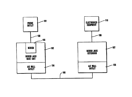
Figure 1 shows a top level block diagram of the major sections of the
invention. In its preferred embodiment, this invention consists of a standard
industry
compatible modem 103 embedded in the base unit of a data link 102. The modem
103 is electrically connected, using standard phone cable 108, to a standard
RJ-11
compatible telephone outlet 101. The modem 103 transmits and receives data to
be
transferred across the telephone lines. The telephone outlet 101 is typically,
though
not necessarily, mounted in a wall. The data link base unit 102 is also
provided with
an A/C power outlet connection 104. The data link base unit 102 communicates
with
the data /ink extension unit 107 across A/C power lines 105, typically
installed in the
walls, via the A/C power outlet connection 104 in the data link base unit 102
and the
A/C power outlet connection 106 in the data link extension unit 107. The data
link
extension unit 107 transmits and receives data across the A/C power lines 105
and
communicates with the user's electronic equipment 110. The data link extension
107
is connected electrically 109 to the user's electronics equipment 110. This
invention
is adapted to connect electrically 109 to such electronics equipment 110 as
including
but not limited to a computer, an Internet device, a television receiver and a
facsimile
machine. Further details on the internal components of the data link base unit
102 and
the data link extension 107 are provided below in the discussion of figures 2
and 3
respectively.
Figure 2 shows the detailed block diagram of the preferred embodiment of the
base unit 102 of the invention. A telephone line connection 206 from the
central
CA 02323513 2000-09-11
WO 99/48218 PCT/US99I06096
6
office (CO) is provided which connects directly to an embedded modem 201
installed
in the base unit 102 of the invention. The data output 207 of the embedded
modem
210 is connected to the digital processor 202. The digital processor 202
receives the
data from the embedded modem 201 and formats and processes the data to be sent
over the power line data link to the extension unit 107. For incoming data
from the
embedded modem 201, the processor utilizes a transmitter 203 to modulate the
data to
be sent over the power lines to the extension unit 107. This data link
invention can
employ a wide variety of different methods of transmission, including but not
limited
to straight data transmissions using simple A/D conversions, frequency
translations,
and/or FDMA, TDMA, CDMA methods. In order to improve the reliability of the
data transmission, the link may use forward error correction (FEC) and spread
spectrum methods well known in the art to improve the signal-to-noise ratio of
the
data link. The transmitter 203 sends the desired modulated data signal to the
power
supply/line interface 205. The receiver 204 demodulates and receives the data
link
signal from the extension 107 via the power supply/line interface 205 and
sends this
data to the digital processor 202 to be processed and reformatted for use by
the
embedded modem 201. The power supply/line interface 205 provides electrical
power
the other base components and as well as providing the connection for the
received
and transmitted carrier signals to and from the transmitter 203 and the
receiver 204
interfacing with the AC power lines 105, via a standard two or three-prong AC
power
plug. Typically, the AC power lines 105 provide 110 VAC, however, alternative
power systems are compatible with the concept of this invention.
Figure 3 shows the detailed block diagram of the preferred embodiment of the
CA 02323513 2000-09-11
WO 99/48218 PCTNS99/06096
7
extension unit 107 of the invention. The power supply/line interface 301, in
the
extension unit 107, provides the power for the other extension unit 107
components as
well as the connections for the received and transmitted carrier signals to
and from the
transmitter 303 and the receiver 302 interfacing with the AC power lines 105,
via a
standard two or three-prong AC plug. Typically, the AC power lines 105 provide
110
VAC, however, alternative power systems are compatible with the concept of
this
invention. The data link receiver 302 receives and demodulates the data,
sending it
over to the extension digital processor 304. The extension digital processor
304
processes the received data from the receiver 302 and decodes, processes and
retrieves
this data and sends the data over to the device interface unit 305. The device
interface
unit 305 conditions and processes the data and provides the interface to
external
electronics equipment, such as digital computer equipment. The device
interface unit
305 receives data from the external electronics equipment 306 and sends this
received
data to the extension digital processor 304, which then processes and
conditions the
data to be sent out to the transmitter 303. The processor utilizes a
transmitter 303 to
modulate the data to be sent over the power lines to the base unit 102. This
data link
can use different methods of transmission, including but not limited to
straight data
transmissions using simple AID conversions, frequency translations, and/or
FDMA,
TDMA, CDMA methods of transmission. In order to improve data transmission
reliability, the link may use forward error correction (FEC) and spread
spectrum
techniques to further improve the data link signal-to-noise ratio. The
transmitter 303
sends the desired modulated signal to the power supply/line interface 301.
The foregoing description is of a preferred embodiment of the invention and
CA 02323513 2000-09-11
WO 99/48218 PGT/US99/06096
8
has been presented for the purposes of illustration and description of the
best mode of
the invention currently known to the inventors. It is not intended to be
exhaustive or
to limit the invention to the precise form, connections, or choice of
components
disclosed. Obvious modifications or variations are possible and foreseeable in
light of
the above teachings. This embodiment of the invention was chosen and described
to
provide the best illustration of the principles of the invention and its
practical
application to thereby enable one of ordinary skill in the art to utilize the
invention in
various embodiments and with various modifications as are suited to the
particular use
contemplated. All such modifications and variations are within the scope of
the
invention as determined by the appended claims when they are interpreted in
accordance with the breadth to which they are fairly, legally and equitably
entitled.