Note: Descriptions are shown in the official language in which they were submitted.
CA 02323540 2004-02-11
ENDOSCOPIC SUTURE SYSTEMS
Technical Field
The invention generally relates to surgical instruments for applying sutures
to tissue.
More particularly, the invention relates to needle deployment mechanisms and
catch
mechanisms.
Background Information
Suturing of body tissue is a time consuming aspect of many surgical
procedures. For
many surgical procedures, it is necessary to make a large opening in the human
body to expose
the area that requires surgical repair. There are instruments available that
allow for viewing of
certain areas of the human body through a small puncture wound without
exposing the entire
body cavity. These instruments, called endoscopes, can be used in conjunction
with specialized
surgical instruments to detect, diagnose and repair areas of the body that
previously required
open surgery to access.
Currently, most surgical instruments used in endoscopic procedures are limited
by the
manner in which they access the areas of the human body in need of repair. In
particular, the
instruments may not be able to access tissue or organs located deep within the
body or that are in
some way obstructed. Also, many of the instruments are limited by the way they
grasp tissue,
apply a suture, or recapture the needle and suture. In addition, many of the
instruments are
complicated and expensive to use due to the numerous parts and/or
subassemblies required to
make them function properly.
Summary of the Invention
The present invention generally is directed to medical instruments for
inserting a suture
through body tissue in a quick and easy manner using needle deployment
mechanisms and catch
CA 02323540 2000-09-13
WO 99/47050 PCT/US99/06085
-2-
mechanisms. In some embodiments, the needle deployment mechanism employs a
linear needle
path. In other embodiments, the needle deployment mechanism employs a curved
needle path.
Some embodiments of the needle deployment and catch mechanism include a
rotatable head.
The instruments of the present invention are useful for application of sutures
to
approximate the sides of a tissue wound in; for example, open, mini-incision,
trans-vaginal, or
endoscopic surgical procedures. These instruments may be used in surgical
procedures such as
burch colposuspension, sacrospinous vaginal vault suspension, paravaginal
repair, radical
prostatectomy, sub-urethral sling, oopherectomy, myomectomy, nissen
fundoplication,
cholecystectomy, and urethral anastomosis, for example.
In one aspect, the invention relates to a suturing instrument comprising an
elongated body
member, a head, and a needle carrier. The head extends from a distal end of
the elongated body
member, and the head defines a longitudinal groove and an opening in
communication with the
longitudinal groove. The head also includes a needle catch disposed within the
opening. The
needle carrier is for holding a needle, and the needle carrier is disposed and
movable within the
longitudinal groove to advance linearly the needle into the opening and
towards the needle catch.
Embodiments according to this aspect of the invention can include the
following features.
The needle carrier can define a needle holder and a recess for suture
material. The needle carrier
can include a U-bend. The needle catch can include an opening with at least
two flexible edges.
The suturing instrument can include a handle located opposite the distal end
of the elongated body
2o member, and the handle can include an actuator coupled to the needle
carrier.
In another aspect, the invention relates to a suturing instrument comprising
an elongated
body member, a needle catch, and a needle Garner. The needle catch includes at
least one opening
for receiving a needle, and the needle catch is movable from within the
elongated body member to
outside of the elongated body member. The needle carrier is for holding the
needle, and the
needle carrier is movable from within the elongated body member to outside of
the elongated
body member.
Embodiments according to this aspect of the invention can include the
following features.
The suturing instrument can include a pusher movably disposed within the
elongated body
member and coupled to the needle carrier and needle catch. The suturing
instrument can also
CA 02323540 2000-09-13
WO 99/47050 PCT/US99/06085
-3-
include a needle catch driver coupled to the pusher and the needle catch
and/or a needle carrier
driver coupled to the pusher and the needle carrier. The pusher can move the
needle carrier and
needle catch from within the elongated body member to outside the elongated
body member. The
pusher can move the needle carrier and needle catch towards each other, and in
one embodiment,
the needle carrier and needle catch can intersect. In addition, the suturing
instrument can include
a distal end with an inner taper to direct the needle carrier and needle catch
towards each other
when moved from within the elongated body member to outside the elongated body
member.
The needle carrier can include a needle holder and a recess for suture
material located it its distal
end. The needle catch can include a point for tissue penetration.
In yet another aspect, the invention relates to a suturing instrument
comprising an
elongated body member, a curved needle, and a pusher. The elongated body
member includes a
distal portion and defines a curved channel within the distal portion. The
curved needle includes a
series of notches and is receivable within the curved channel. The pusher is
movably disposed
within the elongated body member and contacts the notches of the needle to
advance the needle
out of the curved channel.
Embodiments according to this aspect of the invention can include the
following features.
The curved channel and/or the curved needle can comprise a semi-circular
shape. The series of
notches disposed on the curved needle can be located on the needle's concave
or convex surface.
The suturing instrument can define an opening leading to the curved channel
and a protruding
2o edge at the opening for engaging the series of notches of the needle.
In still another aspect, the invention relates to a suturing instrument
comprising an
elongated body member and a head. The elongated body member includes a first
engaging
element located at its distal end. The head includes a second engaging element
located at its
proximal end that engages with the first engaging element of the elongated
body member to
position the head in one of a plurality of orientations with respect to the
elongated body member.
Embodiments according to this aspect of the invention can include the
following features.
The first engaging element can include a female configuration, and the second
engaging element
can include a male configuration for mating with the first engaging element.
Alternatively, the
first engaging element can include a male configuration and the second
engaging element can
CA 02323540 2000-09-13
WO 99/47050 PCT/US99/06085
-4-
include a female configuration for mating with the first engaging element. The
female
configuration can include a series of notches and/or a flexible detent for
engaging the male
configuration, aad the male configuration can include a series of
protuberances, notches, and/or
fluted cuts for engaging the female configuration. The head of the suturing
instrument can be
secured in position by engaging the first and second engaging elements, and
the head can be
rotated when the first and second engaging elements are disengaged.
Alternatively, the head can
be positioned by rotating one engaging element with respect to the mating
engaging element, and
in this configuration the head is secured in place by mechanical engagement of
the two engaging
elements. The head can be rotated with respect to the body member in
increments as small as
10°. The head can include a needle deployment mechanism and a catch
mechanism located at its
distal end, and the distal end can be bullet-shaped to maintain a body lumen
in a dilated state.
Additional embodiments according to any of the foregoing aspects of the
invention can
include the following features. The elongated body member of the suturing
instrument can be
adapted to access remote tissue or organs within the body. The elongated body
member can
include a bend or bends. The bend can take the shape of an elbow, a soft
curve, a double curve,
or any other shape suited to access remote organs or tissue within the body.
The elongated body
member can be preshaped and permanently bent and comprised of sturdy or
resilient material.
The elongated body member can also be comprised of a malleable material and
thus be bent and
shaped to a desired form. The shaping can be done manually outside the body,
or remotely within
2o the body to fit the required course for the instrument.
In still yet another aspect, the invention relates to a needle catch for use
with a suturing
instrument. The needle catch includes at least one opening for receiving a
needle, and the needle
catch includes a point for tissue penetration. The point can be formed by at
least two tapered
edges. The needle catch can also be bent to include convex and concave
surfaces, and the needle
2S catch can comprise stainless steel.
These and other objects, along with advantages and features of the present
invention
herein disclosed, will become apparent through reference to the following
description of
embodiments of the invention, the accompanying drawings, and the claims.
CA 02323540 2000-09-13
WO 99/47050 PC'T/US99/06085
-5-
Brief Description of the Drawings
In the drawings, like reference characters generally refer to the same parts
throughout the
different figures. Also, the drawings are not to scale; emphasis instead
generally being placed
upon illustrating the principles of the invention.
FIG. lA is a top view of the distal end of one embodiment of the suturing
system
according to the invention.
FIG. 1 B is a side view of the distal end of one embodiment of the suturing
system
according to the invention featuring a Z-bend needle catch.
FIG. 1 C is a longitudinal section view of the distal end of one embodiment of
the suturing
system according to the invention taken along line C-C.
FIG. 1D is a side view of an embodiment of a needle and suture for use with
the invention.
FIG. 2A is a schematic representation of one embodiment of the invention for
suturing
transversely positioned tissue.
FIG. 2B is another schematic representation of one embodiment of the invention
for
suturing transversely positioned tissue.
FIG. 3A is a section view of the distal end of the suturing system of the
embodiment
shown in FIGS. 2A and 2B in the retracted position.
FIG. 3B is a section view of the distal end of the suturing system of the
embodiment
shown in FIGS. 2A and 2B in the extended position.
FIG. 4 is a perspective view of one embodiment of a needle catch for use with
the suturing
system of FIGS. 2 and 3.
Fig. SA is a longitudinal section view of the distal end of one embodiment of
the suturing
system of the invention.
Fig. SB is a cross-section view of the distal end of one embodiment of the
suturing system
of the invention taken at line B-B.
CA 02323540 2000-09-13
WO 99/47050 PCT/US99/06085
-6-
FIG. SC is a side view of one embodiment of a needle with suture.
FIG. SD is a perspective side view of one embodiment of a pusher.
FIGS. 6A-6C are schematic, perspective, side-view representations of one
embodiment of
the suturing system of the invention featuring an elbow-shaped, elongated body
member with a
rotatable head shown in various rotated positions, but not showing a needle
deployment
mechanism or a needle catch mechanism.
FIGS. 6D-6F are schematic representations of some details of the rotatable
head shown in
FIGS. 6A-6C and featuring a needle deployment mechanism, a needle catch
mechanism, and the
engaging elements.
FIG. 7A is a schematic representation of one embodiment of a suturing system
of the
present invention featuring an elbow-shaped, elongated body member with a
rotatable suturing
head used in connection with a grasper.
FIG. 7B is a schematic representation of one embodiment of a suturing system
of the
present invention showing a sectional view of the grasper in the extended
position.
FIG. 7C is a schematic representation of one embodiment of a suturing system
of the
present invention shown located in the urethra and bladder.
Descriution
In general, the present invention is directed to various improvements of
components and
mechanisms of needle deployment systems for suturing devices, such as those
disclosed in U.S.
2o Patent No. 5,713, 910 to Gordon et al., U.S. Patent No. 5,578,044 to Gordon
et al., U.S. Patent
No. 5,575,800 to Gordon, U.S. Patent No. 5,540,704 to Gordon et al., U.S.
Patent
No. 5,458,609 to Gordon et al., and U.S. Patent No. 5,364,408 to Gordon, all
of which are
incorporated herein by reference in their entirety.
Referring to FIGS. lA and 1B, the distal end 10 of one embodiment of a
suturing system
according to the present invention defines a distal longitudinal groove 12
located at the tip 14 of
the distal end 10 and intersecting with the distal wall 16 of an opening 18.
The suturing system
CA 02323540 2000-09-13
WO 99/47050 PCT/US99/06085
can include a handle located opposite the distal end of the elongated body
member. The handle
could take a variety of forms, for example, the handle could be one of the
types used with Boston
Scientific Corporation suturing systems, in particular the Laurus-Capio Push &
Catch suturing
system. The distal end 10 may be fabricated from molded or machined plastic
material such as
polycarbonate or glass-filled polycarbonate. Located within the opening 18 and
in a plane
substantially perpendicular to the needle carrier 44 path is a needle catch 20
having a distal side
22 resting on the floor 24 of the opening 18 and a proximal side 26 resting
against the proximal
wall 28 of the opening 18. Between the two sides 22 and 26, the needle catch
20 forms a concave
bend 30 proximal to side 22 and a convex bend 32 proximal to side 26 forming a
Z-like shape.
1 o Between the two sides 22 and 26 of the needle catch 20 and aligned with
the distal longitudinal
groove 12 is an opening 34 formed by two flexible edges 36 and a mouth 38. The
lateral sides 40
of the needle catch 20 wrap around the distal end 10 of the suturing system
and are secured in
place by notches 42 turned inward into the body of the distal end, or
alternatively into small
grooves. The needle catch 20 is preferably made of thin stainless steel
material, in particular, high
temper stainless steel. The needle catch may be manufactured by stamping,
laser machining or
chemical etching, for example.
Referring to FIG. 1 C, in the longitudinal groove 12 is positioned a needle
carrier 44
having a convex U-bend 46. At the end 48 of the needle carrier is a needle
holder 50 that defines
a hole with a recess 52 for lodging the needle 54 and suture 56. When the
needle carrier 44 is
2o actuated along the longitudinal axis of the elongated body member, the
needle carrier 44 advances
the needle 54 linearly from the distal end of the longitudinal groove 12,
through the tissue located
within the opening 18, and into the needle catch 20. The release of the needle
54 from the needle
carrier 44 occurs upon reverse motion of the needle carrier 44.
Referring to FIG. 1D, suitable needles 54 for positioning into the needle
holder 50, include
a neck 58 with a hole at one of its ends for inserting a suture 56 and at
least one shoulder 60. The
body 62 of the needle 54 is tapered from the shoulder 60 to the point 64 to
facilitate tissue
penetration and insertion into the opening 34 of the needle catch 20. The
shoulders 60 are made
of larger dimensions than the opening 34 of the needle catch 20. During
insertion of the needle
54 into the opening 34 of the needle catch 20, the edges 36 of the opening 34
flex upon pressure
exerted by the body 62 of the needle 54 at the shoulders 60 and permit entry
of the needle 54 into
the opening 34. The needle 54 is retained within the needle catch 20 when the
edges 36 return to
CA 02323540 2000-09-13
WO 99/47050 PCT/US99/06085
_g_
their original position once the shoulders 60 have entered the opening 34 and
the neck 58 of the
needle 54 is lodged in the opening 34. Preferably, the neck 58 has smaller
dimensions than the
opening 34 to permit the edges 36 to return to their original position. The
needle 54 is released
from the needle catch 20 by sliding the neck 58 of the needle 54 toward the
mouth 38 of the
opening 34. The dimensions of the mouth 38 are larger than the dimensions of
the shoulders 60
to permit the release of the needle 54 from the needle catch 20.
Needle deployment/catch systems as described in FIGS. lA 1C can be made with
various
dimensions as necessary for a specific application. In particular, this
instrument is well suited to
being made to minute dimensions. For example, suitable dimensions to use for a
instrument for
1 o performing an urethral anastomosis can be as follows: the tip 14 may be
1.15 in. long, 0.205 inch
wide, and 0.275 in. high; the distal end 10 may be 0.058 in. in diameter; the
needle Garner 44 may
be 0.032 in. in diameter; the distance between the distal wall 16 of the
opening 18 to the
opening 30 of the needle catch 20 may be 0.15 in. long.
One advantage of the suturing system/instrument of FIGS. lA-1D is that it
requires fewer
parts; thereby, making it easier and less expensive to manufacture than known
devices.
Referring to FIGS. 2A and 2B, in another embodiment of the suturing instrument
66
according to the present invention, the instrument is configured to deploy a
needle 54 through
tissue 68 positioned substantially perpendicular to the elongated body member
82 of the suturing
instrument 66. The suturing instrument comprises a pusher 72 having a knob 74
at the proximal
2o end and an elongated portion 76 extending from the knob 74 to the distal
end and connected to
the needle carrier driver 78 and the needle catch driver 80. The elongated
portion 76 of the
pusher 72 is positioned within an elongated body member 82, which includes a
tubular body 70
that extends from the proximal end to the distal end where it contacts the
tissue 68 to be sutured.
The elongated body member 82.includes a handle portion 84 located at the
proximal end that
provides grip for manipulation of the instrument and support for actuating the
pusher 72.
In the retracted position, as shown in FIG. 2A, the tissue 68 to be sutured is
positioned at
the distal end of, and substantially perpendicular to, the elongated body
member 82. The needle
carrier 44 and the needle catch 20 are positioned within the elongated body
member 82, and the
knob 76 is afar from the handle portion 84 of the elongated body member 82. In
an extended
CA 02323540 2000-09-13
WO 99/47050 PCT/US99/06085
-9-
position, as shown in FIG. 2B, the needle carrier 44 holding a needle 54 and
the needle catch 20
are moved to a position outside the elongated body member 82 and into the
tissue 68. The needle
carrier 44 and the needle catch 22 can be moved simultaneously by the needle
carrier driver 78
and the needle catch driver 80 when actuated by the pusher 72. The needle
carrier 44 and the
needle catch 22 meet afar from the distal end of the elongated body member and
into the tissue 68
such that the needle 54 with a suture 56 attached thereto is pushed through
the opening 34 of the
needle catch 20 until the shoulders 60 of the needle 54 snap there through. In
the extended
position, the knob 74 of the pusher 72 is proximal to, and in contact with,
the handle 84 of the
elongated body member 82. The suture 56 and the needle 54 are brought back out
of the
tissue 68 with the needle catch 20 when the suturing system is returned to its
retracted position.
To facilitate return to the retracted position, the knob 74 of the pusher 72
may alternatively
comprise a ring for insertion of a finger by the operator of the instrument.
Refernng to FIGS. 3A and 3B, showing a longitudinal section of the distal end
of a
particular embodiment of a suturing instrument 66, the interior wall 86 of the
elongated
body member 82 tapers inward at the distal end. When the pusher 72 is
depressed, moving from
afar towards the handle 84, the elongated portion of the pusher 72 pushes
simultaneously the
needle Garner driver 78 and the needle catch driver 80 towards their extended
position. The
tapered interior wall 86 directs both, the needle Garner 44 and the needle
catch 20 towards each
other when pusher 72 is depressed.
2o Alternatively, the needle carrier driver 78 and needle catch 80 can be
prebent or include a
pivotal system such as a pivot pin or scissors so that the paths of the needle
carrier 44 and the
catch 20 run from separated lateral positions within the elongated body member
82 to an
intersecting point outside the elongated body member 82. In the fully extended
position, shown in
FIG. 3B, the needle 54 has been pushed through the opening 34 of the needle
catch 20 within the
tissue 68 to be sutured. When the suturing instrument 66 is returned to its
retracted position, as
shown in FIG. 3A, the needle 54 is retained by the needle catch 20 and drawn
out of the tissue 68.
The needle 54 can then be released from the needle catch 20 by pulling the
needle 54 and cutting
the suture 56 off
A needle catch 20, suitable for use in the suturing instroment 66 shown in
FIGS. 2A and
2B, is shown in FIG. 4. The needle catch 20 is preferably made of a sheet of
stainless steel which
CA 02323540 2000-09-13
WO 99/47050 PCT/US99/06085
-10-
is bent to provide a concave surface 88 and a convex surface 90 for rigidity.
The needle catch 20
can contain several openings 34. The needle catch 20 also comprises two
tapered sides 92 that
merge into a point 94 for easy penetration of tissue 68. The needle catch 20
can be mounted and
secured to the needle catch driver 80 either by permanent bond using glue or
any known
interlocking system such as pressure snap-in.
Refernng to FIGS. SA-SD, in another embodiment of the invention the suturing
instrument includes an elongated body member 82 having a channel 96 extending
from the head
portion to the distal end. FIG. SA shows a longitudinal sectional view of the
distal end of the
suturing instrument 66 with the distal end of channel 96 intersecting
tangentially with a curved
guiding channel 98. The guiding channel 98 is positioned along the
longitudinal axis of the
elongated body member 82 and defines two openings 100, 102 on the lateral side
of the elongated
body member 82. The proximate opening 100 permits ingress of a needle 104
(shown in FIG.
SC) having a curved shape and a series of notches 106 on a portion of the
convex surface 108.
The point 110 of the needle having smooth surfaces and being tapered to
facilitate penetration of
tissue 68. The tail 112 of the needle 104 having a hole to permit fixation of
the suture
material 56.
Referring to FIGS. SA and SB, a pusher 114 is positioned in the longitudinal
channel 96
with the head 116 forming an edge to provide support and engage into the
notches 106 of the
needle 104 introduced into the guiding channel 98.
On the outer wall 118 of the distal opening 102 is positioned a protruding
edge 120 that
provides for locking of the needle 104 during egress from the guiding channel
98. Each push of
the pusher 114 moves the needle 104 within the guiding channel 98 from the
proximal
opening 100 to the distal opening 102 until a notch 106 locks onto the
protruding edge 120. A
pull of the pusher 114 slides the head 116 of the pusher 114 against the
sliding sides of the
notches 106 until it engages in a notch 106 closer to the tail 112 of the
needle. The push and pull
motion is repeated several times until all of the needle 104 has passed
through the guiding
channel 98, and into tissue positioned parallel to, and in contact with, the
distal opening 102. The
needle 104 can then be extracted from the tissue once the point 110 resurfaces
out of the mass of
the tissue with surgical pliers, tweezers, hemostats, needle holders, or other
appropriate surgical
instrument.
CA 02323540 2000-09-13
WO 99/47050 PCT/US99/06085
-11-
FIG. SB shows a cross-sectional view of the distal end of the suturing
instrument at the
intersection between the longitudinal channel 96 and the guiding channel 98.
FIG. SD shows a prospective view of the pusher 114 with the head 116.
In yet another embodiment, the instrument can be adapted to facilitate access
into the
abdominal cavity and the placement of sutures) radially in a body lumen. Such
instrument may
be particularly useful where anastomosis is required such as urethral
anastomosis following radical
prostatectomy or in blood vessel or bowel anastomosis. Referring to FIGS. 6A
6C, the suturing
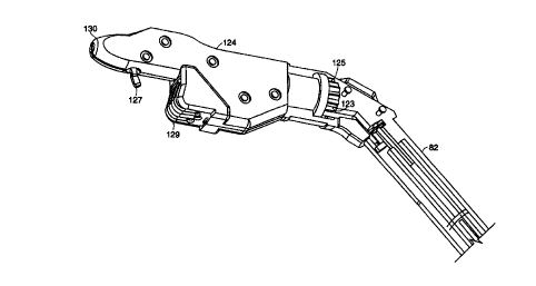
instrument 66 includes an elongated body member 82 and a rotatable head 124.
The elongated
body member 82 can include an elbow 122 (or bend). The head 124 rotates by
angular
increments. The elongated body member 82 includes an engaging element located
at its distal end
128. The head 124 includes an engaging element located at its proximal end 126
for mating with
the engaging element of the elongated body member 82. The head 124 includes a
dilator cap or a
bullet-shaped end at the distal end 130 of the head 124 to maintain the
urethra or any body lumen
in a dilated configuration. The rotation of the head 124 is performed manually
between each
application of a suture in a body lumen and before reloading with the needle
and suture to permit
application of a series of sutures along the circumference of the lumen, at
incremental angular
positions that can be as small as 10°. The embodiment of the suturing
instrument featuring an
elbow and rotatable head is particularly adapted to perform suturing after
removal of the prostate
to connect the bladder to the urethra or generally following any other type of
resection.
In one embodiment, the rotatability of the head 124 is accomplished with the
structure
depicted in FIGS. 6D-6F. The head 124 includes an engaging element with a male
configuration
123. The male configuration 123 includes a series of fluted cuts 133 located
along 330° of its
perimeter. The male configuration 123 includes a stop to prevent the head from
rotating 360°.
The elongated body member 82 includes an engaging element with a female
configuration 125 and
a flexible detent 131. The female configuration 125 is a substantially
circular recess with the
flexible detent mounted within the elongated body member 82 and protruding
into the
substantially circular recess. The flexible detent 131 can be a length of
spring wire or a pin, and
can be made of nitinol. The head 124 can be positioned by rotating the male
configuration 123
engaging element with respect to the female configuration 125 engaging
element, deflecting the
flexible detent 131, and then allowing the flexible detent 131 to mechanically
engage the fluted cut
CA 02323540 2000-09-13
WO 99/47050 PCT/US99/06085
-12-
133 which corresponds to the desired angular orientation. The head can be
positioned in angular
increments of 30°. In addition, the head 124 depicted in FIGS. 6D-6F
includes a needle
deployment mechanism 127 and a needle catch mechanism 129.
Referring to FIGS. 7A-7C, to further facilitate positioning of the instrument
within the
body passageway, a grasper device 132 may be introduced into the body cavity
by a second point
of entry. The grasper device comprises a hollow elongated body member 134 for
housing a pair
of spring-loaded jaws or tweezers 136 at the distal end of the body member
134. The
tweezers 136 are close together in a retracted position as shown in FIG. 7A
and open to permit
gasping of the knob 138 located on the distal end of the head 124 in an
extended position as
shown in FIG. 7B. When closed around the ball or knob 138, the grasping
tweezers 136 can
allow rotatable movement of the knob 13 8 and thus rotation of the head 124.
The proximal end of the grasper device 132 features a button 140 that is
positioned at the
proaamal end of a wire 142. The wire 142 is connected to the tweezers 136 at
the distat end. The
device is maintained in the retracted position by a spring 144 located in the
head 146 of the
grasper 132 which rests its proximal end against the button 140 and its distal
end against a
protuberance 148 positioned in the interior wall of the head 146.
FIG. 7C shows both the grasper 132 and the suturing instrument 66 located in
the
urethra 150 and the bladder I52 below the public bone 154 of a male following
prostatectomy.
The void left by the removed prostate is addressed by using the instrument 66
together with the
2o grasper 132 to insert sutures all around the end of the urethra 150 to join
it to the bladder 152.
In yet other embodiments of the instant invention, the aforementioned suturing
systems
can be used to deploy an anchor or fastener that is to remain in the tissue.
Such anchor or
fastener may be; for example, a barbed needle, a metal clip, or a staple.
Having described embodiments of the invention, it will be apparent to one
skilled in the art
that other embodiments incorporating the concepts disclosed herein may be used
without
departing from the spirit of the invention. Thus, numerous other embodiments
include, but are
not limited to: changes in the dimensions of the instruments; the type of
materials employed; the
location and type of needle, anchor or fastener; and needle loading
mechanisms. All are within
the scope of the present invention. The described embodiments are to be
considered in all
CA 02323540 2000-09-13
WO 99/47050 PC"fNS99/06085
-13-
respects only as illustrative and not restrictive. Therefore, it is intended
that the scope of the
present invention be only limited by the following claims.
What is claimed is: