Note: Descriptions are shown in the official language in which they were submitted.
CA 02323549 2000-09-13
WO 99/47834 PCT/CA99/00202
BELT TENSIONER WITH REDUCED 17LT ACTION ON SUPPORT STRUCTURE AND METHOD FOR
INSTALLING
THE SAME
Field of Invention
This invention relates to a belt tensioner. In particular, this invention
relates to an anti-
tilt timing belt and a method of installing such a tensioner.
Background of Invention
In conventional belt tensioner arrangements, the belt load force applied
during
installation, while the mounting bolt is still loose, has a natural tendency
to apply a tilting force
to the tensioner. More specifically, the loose bolt tends to pivot or tilt
around the area at which
the bolt enters into mounting structure. The installation shaft and pivot
shaft also tend to bend
or pivot about this area as a result of the belt load force and loose mounting
bolt.
When the bolt is tightened after the installation shaft is rotated to move the
tensioner to
the nominal installation position, the bolt, installation shaft, and pivot
shaft tend to straighten
against the tilting action of the belt load force. It can be appreciated that
this straightening
action can cause the tensioner arm to rotate away from its nominal
installation position. As a
result, the tensioner might not be installed in its proper static position.
While a position
indicating pointer connected with the belt tensioner lever arm might be
brought out of alignment
with a position correct indicator during this tightening of the bolt to alert
the operator to re-
adjust the tensioner, the inaccurate positioning of the tensioner may go
unnoticed due to the fact
that the hysteresis forces (friction) of the tensioner may be restricting the
final rotation of the
belt tensioner lever arm when the tensioner and belt are static. The incorrect
tensioner location
may, therefore, only be detected after first running the engine (which will
release the frictional
"stickiness" of the tensioner).
In order to reduce the tilting of the tensioner during the installation
process and the
consequent unwanted movement of the lever arm caused by the final tightening
of the mounting
bolt, it has also become customary to specify a precise pre-tightening torque
for the mounting
bolt prior to the application of the installation force. The drawbacks of this
practice are twofold.
First, it increases the frictional forces between the tensioner and the
tensioner mounting surface
on the engine, requiring higher installation forces. This may also cause
possible scarring of the
surfaces resulting in tensioner angularity errors. Second, the practice adds
extra labor and cost
on the engine assembly line without satisfactorily solving the problem of
erratic tensioner
positioning.
U.S. Patent No. 5,244,438 ("438 patent) discloses a belt tensioner that
employs a flanged
eccentric bush that extends in an axial direction essentially abutting the
belt centerline plane.
There are a number of shortcomings to this design. First, the flanged
eccentric bush is truncated
in that its axial extent terminates at the same location in which its
engagement with the
surrounding bearing neck terminates. This truncated configuration is
impractical from a
manufacturing and assembly standpoint. For example, because the eccentric bush
is truncated, it
may fall out from the bearing neck under the force of gravity (perpendicular
to the bush axis
-1-
CA 02323549 2000-09-13
WO 99/47834 PCT/CA99/00202
when mounted on an engine) prior to the mounting screw being employed to mount
the
tensioner on the engine.
U.S. Patent No. 5,759,125 suggests a belt tensioner arrangement comprising a
rigid
support base having a longitudinal slot for allowing translational
displacement of the support
base to adjustably secure the support base to the vehicle engine. This
movement is not restricted
to an arcuate, connecting-rod type movement, but is free to move in any
direction as dictated by
an externally applied force. This freedom of movement is no better or even
worse than the
connecting rod type arcuate movement with regard to proper alignment of the
tensioner during
installation.
io Summary of Invention
To overcome the difficulties noted above, the present invention provides an
arrangement
in which the tensioner tilt during installation is counteracted, thereby
ensuring accurate
installation. This can be done manually, for example, by use of a tool or by a
particular
construction of the tensioner, e.g., in the way it interfaces with a mounting
bolt.
In accordance with one preferred embodiment of the present invention, this is
accomplished by providing a belt tensioner having integral structure that
isolates the main points
of installation tilting force engagement to positions remote from the engine
mounting surface
than the belt width centerline plane.
The present invention provides a belt tensioner for a motor vehicle engine,
comprising a
pivot shaft; an eccentric pivoted structure mounted for pivoted movement on
the pivot shaft; a
rotatable pulley member mounted for rotation on the eccentric pivoted
structure; a spring
constructed and arranged to bias the eccentric pivoted structure in a
direction tending to force
the pulley member into tensioning engagement with a belt trained about the
pulley member
when the belt tensioner has been installed on the motor vehicle engine; an
eccentric installation
shaft received within the pivot shaft, a mounting bolt constructed and
arranged to extend
through the installation shaft to secure the belt tensioner to the motor
vehicle engine, the
installation shaft being rotatable about the mounting bolt to move the pulley
into tensioning
engagement with the belt and to pre-load the spring to bias the eccentric
pivoting structure;
wherein a belt load force applied by the belt to the belt tensioner pulley is
centered about a belt
centerline plane bisecting a width of the belt; the pivot shaft contacting the
installation shaft at a
first contact portion opposing the belt load force, and the installation shaft
contacting the
mounting bolt at a second contact portion opposing the belt load force, at
least one of the first
and second contact portions being limited to a location on one side of the
belt centerline plane
remote from the motor vehicle engine, the installation shaft having a portion
thereof disposed
closer to the motor vehicle engine than the at least one of the first and
second contact portions
limited to the one side of the belt centerline plane.
A further shortcoming of the '438 patent is that it fails to provide a
mechanism for
adequately countering the tilting forces applied to the tensioner during
installation.
Accordingly, it is another object of the present invention to overcome this
shortcoming as well.
-2-
CA 02323549 2000-09-13
WO 99/47834 PCT/CA99/00202
Thus, the present invention further provides a belt tensioner for a motor
vehicle engine, and
constructed and artanged to be mounted on a mounting surface of the motor
vehicle engine, the
belt tensioner comprising a pivot shafft, an eccentric pivoted structure
mounted for pivoted
movement on the pivot shaft, a rotatable pulley member mounted for rotation on
the eccentric
pivoted structure, a spring constructed and arranged to bias the eccentric
pivoting structure in a
direction tending to force the pulley member into tensioning engagement with a
belt trained
about the pulley member when the belt tensioner has been installed on the
motor vehicle engine,
an eccentric installation shaft received within the pivot shaft, a mounting
bolt constructed and
arranged to extend through the installation shaft to secure the belt tensioner
to the motor vehicle
engine, the installation shaft being rotatable about the mounting bolt to move
the pulley into
tensioning engagement with the belt and to pre-load the spring to bias the
eccentric pivoting
structure, wherein a belt load force applied by the belt to the belt tensioner
pulley is centered
about a belt centerline plane bisecting a width of the belt, the pivot shaft
contacting the
installation shaft at a first contact portion opposing the belt load force,
and the installation shaft
contacting the mounting bolt at a second contact portion opposing the belt
load force, at least
one of the first and second contact portions being limited to a location on
one side of the belt
centerline plane remote from the motor vehicle engine, wherein the at least
one of the first and
second contact portions is spaced a distance from the belt centerline plane,
the distance being at
least 7% of a distance between the belt centerline plane and the tensioner
mounting surface of
the motor vehicle engine.
In accordance with another type of tensioner device disclosed herein, a
further
shortcoming of prior art belt tensioner arrangements is overcome. In certain
prior art tensioners,
such as that in the '438 patent, the belt tensioner is guided by a connecting
rod type arrangement
when the tensioner is moved into tensioning engagement with a belt. As a
result, the tensioner
moves in an arcuate path and may not be in ideal alignment for proper
tensioning of the belt
when the tensioner is eventually tightened into its final installation
position. It is desirable
therefore to provide a belt tensioner that does not require this connecting
rod controlled arcuate
movement during installation.
It is an object of the present invention to provide a belt tensioner that is
with guiding
structure that restricts movement of the tensioner during installation to
linear movement for
improved alignment during installation. In accordance with this object, the
present invention
provides a belt tensioner for a motor vehicle engine, comprising a pivot
shaft; an eccentric
pivoted structure mounted for pivoted movement on the pivot shaft; a rotatable
pulley member
mounted for rotation on the eccentric pivoted structure; a spring constructed
and arranged to bias
the eccentric pivoted structure in a direction tending to force the rotatable
pulley member into
tensioning engagement with a belt trained about the pulley member; a mounting
bolt constructed
and arranged to mount the belt tensioner on the motor vehicle engine, the
pivot shaft being
movable relative to the mounting bolt and towards the belt during a belt
tensioner installation
procedure; linear guiding structure providing surfaces of interengagement
between the belt
-3-
CA 02323549 2000-09-13
WO 99/47834 PCT/CA99/00202
tensioner and the motor vehicle engine to limit movement of the pivot shaft to
linear movement
toward the belt during the installation procedure.
It is a further object of the invention to provide a method for installing a
belt tensioner
which counteracts the normal tilting forces during installation. In accordance
with this object,
the present invention provides a method of installing a belt tensioner
comprising a pivot shaft, a
pivoted structure mounted on the pivot shaft, a rotatable pulley member
mounted for rotation on
the pivoted structure, a spring that biases the pivoted structure in a
direction tending to force the
pulley member into tensioning engagement with a belt when the belt tensioner
is installed on a
motor vehicle engine, the method comprising mounting the belt tensioner on the
motor vehicle
l o engine with a mounting bolt moving the pulley into forcible engagement
with the belt so as to
cause pivoting movement of the pivoted structure against the bias of the
spring, the belt
applying a counteracting belt load force to the pulley, the belt load force
tending to tilt the
tensioner and applying an external force to the belt tensioner in a direction
which tends to
balance the belt load force so as to reduce or eliminate tilting of the
tensioner during installation.
In accordance with another aspect of the present invention, an integrated
eccentric
installation pivot shaft is provided, as opposed to a pivot shaft and separate
eccentric installation
shaft. In accordance with this aspect, there is provided a belt tensioner for
a motor vehicle
engine which comprises an eccentric installation pivot shaft. An eccentric
pivoted structure is
mounted for pivoted movement on the eccentric pivot shaft. A rotatable pulley
member is
mounted for rotation on the eccentric pivoted structure. A spring is
constructed and arranged to
bias the eccentric pivoted structure in a direction tending to force the
pulley member into
tensioning engagement with a belt trained about the pulley member when the
belt tensioner has
been installed on the motor vehicle engine. A mounting bolt is constructed and
arranged to
extend through the eccentric pivot shaft to secure the belt tensioner to the
motor vehicle engine.
The eccentric pivot shaft is rotatable about the mounting bolt to move the
pulley into tensioning
engagement with the belt and to pre-load the spring to bias the eccentric
pivoting structure,
wherein a belt load force is applied by the belt to the belt tensioner pulley
centered about a belt
centerline plane bisecting a width of the belt. The eccentric pivot shaft
contacts the mounting
bolt at a contact portion which opposes the belt load force. The contact
portion is limited to a
location on one side of the belt centerline plane remote from the motor
vehicle engine.
In accordance with another aspect of the invention, the tensioner structure
tilts the
tensioner beyond perpendicular relation with the engine mounting surface, to
actually tilt the
tensioner towards the belt to accommodate for stretched belts or hysteresis of
the tensioner arm
in strongly damped tensioners.
Description of the Drawings
Fig. 1 is a front plan view of a belt tensioner in accordance with a first
embodiment of
the present invention.
Fig. 2 is a cross-sectional view taken along the line 2-2 in Fig. 1.
Fig. 3 is a longitudinal sectional view generally depicting an installation
shaft and a pivot
-4-
CA 02323549 2000-09-13
WO 99/47834 PCT/CA99/00202
shaft of a second embodiment of a tensioner in accordance with the present
invention.
Fig. 4 is a longitudinal sectional view generally depicting an installation
shaft and a pivot
shaft of a third embodiment of a tensioner in accordance with the present,
invention.
Fig. 5 is a longitudinal sectional view generally depicting an installation
shaft and a pivot
shaft of a fourth embodiment of a tensioner in accordance with the present
invention.
Fig. 6 is a longitudinal sectional view generally depicting an installation
shaft and a pivot
shaft of a fifth embodiment of a tensioner in accordance with the present
invention.
Fig. 7 is a longitudinal sectional view generally depicting an installation
shaft and a pivot
shaft of a sixth embodiment of a tensioner in accordance with the present
invention.
Fig. 8 is a longitudinal sectional view generally depicting an installation
shaft and a pivot
shaft of a seventh embodiment of a tensioner in accordance with the present
invention.
Fig. 9 is a longitudinal sectional view generally depicting an installation
shaft and a pivot
shaft of an eighth embodiment of a tensioner in accordance with the present
invention.
Fig. 10 is a longitudinal sectional view generally depicting a pivot shaft of
a ninth
embodiment of a tensioner in accordance with the present invention.
Fig. 11 is a top plan view depicting an installation shaft identical to that
in the
embodiment of Fig. 3.
Fig. 12 is a longitudinal sectional view taken along line 12-12 of Fig. 11.
Fig. 13 is a top plan view depicting an installation shaft of a tenth
embodiment of a
tensioner in accordance with the present invention.
Fig. 14 is a longitudinal sectional view taken along line 14-14 of Fig. 13.
Fig. 15 is a side plan view of a tensioner with an external installation pivot
or linear
installation stroke tensioner in accordance with an eleventh embodiment of the
present
invention.
Fig. 16 is a side plan view of a tensioner with an external installation pivot
or linear
installation stroke tensioner in accordance with a twelfth embodiment of the
present invention.
Fig. 17 is a side plan view of a tensioner identical to the embodiment of Fig.
16 except
that the installation force is being applied in a different direction in
accordance with the method
of a thirteenth embodiment of the present invention.
Fig. 18 is a side plan view of a tensioner with an external installation pivot
or linear
installation stroke tensioner in accordance with a fourteenth embodiment of
the present
invention.
Fig. 19 is a side plan view of a tensioner with an external installation pivot
or linear
installation stroke tensioner modified for simultaneous application of two
separate installation
forces in accordance with a fifteenth embodiment of the present invention.
Fig. 20 is a side plan view of a tensioner with an external installation pivot
or linear
installation stroke tensioner also indicating the disposition of an
installation tool in accordance
with a sixteenth embodiment of the present invention.
Fig. 21 is a side plan view of a tensioner with an external installation pivot
or linear
-5-
CA 02323549 2000-09-13
WO 99/47834 PCT/CA99/00202
installation stroke tensioner also indicating the disposition of an
installation tool in accordance
with a seventeenth embodiment of the present invention. .
Fig. 22 is a side plan view of a tensioner with an external installation pivot
or linear
installation stroke tensioner in accordance with an eighteenth embodiment of
the present
invention.
Fig. 23 depicts a side plan view of a tensioner identical to the embodiment of
Fig. 22
except the installation force is being applied in a pulling manner (as opposed
to pushing) in
accordance with the method of a nineteenth embodiment of the present
invention.
Fig. 24 is a side plan view of a tensioner with an extesmal installation pivot
or linear
1o installation stroke tensioner in accordance with a twentieth embodiment of
the present invention.
Fig. 25 is a partial section side view of a belt tensioner with a linear
installation stroke in
accordance with a twenty-first embodiment of the present invention.
Fig. 26 is a partial section top view of the belt tensioner embodiment in Fig.
25, the
partial section being taken along line 26-26 of Fig. 27.
Fig. 27 is a longitudinal sectional view taken along the line 27-27 of Fig.
26.
Fig. 28 is a side plan view of the belt tensioner embodiment in Fig. 27 and
depicting the
disposition of an installation tool in accordance with the present invention.
Fig. 29 is a plan top view of the tensioner embodiment depicted in Fig. 28.
Fig. 30 is a side view of the tensioner embodiment depicted in Fig. 28, but
the view
being taken from a position displaced 90 relative to Fig. 28.
Fig. 31 is a side plan view of a belt tensioner with a linear installation
stroke tensioner
and depicting the disposition of an installation tool in accordance with a
twenty-second
embodiment of the present invention.
Fig. 32 is a top plan view of the tensioner embodiment depicted in Fig. 31.
Fig. 33 is a right side view of the tensioner embodiment depicted in Fig. 31.
Fig. 34 is a plan view of a belt tensioner utilizing an external pivot used
for installation
and that can be adapted to employ an anti-tilt device in accordance with the
present invention.
Detailed Description of the Invention
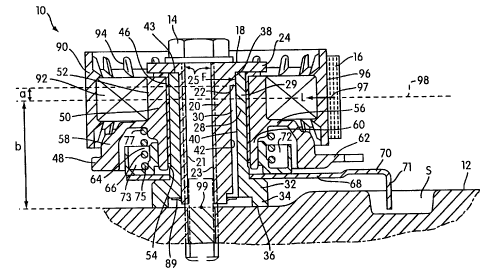
Referring particularly to the drawings, Fig. I is a front plan view of a belt
tensioner 10 in
3o accordance with a first embodiment of the present invention. The belt
tensioner 10 is shown
bolted on a tensioner mounting surface, which could be an engine block or
frame, generally
indicated at 12. Tension 10 is mounted to mounting surface 12 by a threaded
mounting bolt 14
and is in tensioning engagement with a drive or timing belt 16. A tubular
installation shaft 18
has a main tubular portion 20 (see Fig. 2) disposed eccentrically around the
mounting bolt 14
and has a radially extending flange 24 at an end of the tubular portion 20
furthest away from
surface 12. A generally cylindrical pivot shaft 28 is disposed around the
installation shaft 18
and is eccentric to the mounting bolt 14 by virtue of the installation shaft.
An annular lever arm
or pivoting eccentric 48 has a main tubular eccentric portion 50 (See Fig. 2)
disposed in
surrounding relation to the pivot shaft 28. A ball bearing 92 is disposed
around the eccentric
-6-
CA 02323549 2000-09-13
WO 99/47834 PCT/CA99/00202
portion 50, and a pulley 90 is disposed around the ball bearing 92. Fig. 1
shows the belt 16
engaged with an outer surface 96 of the pulley 90. The lever arm 48 has a
radially projecting
pointer 62 that extends radially outwardly beyond the radial extent of pulley
90, and a notch 63
in the tip of the pointer 62 is seen in alignment with an indication mark I on
an extension 70 of a
base plate 68. Fig. 1 also shows that the base plate extension 70 is received
within a slot S in the
tensioner mounting surface 12.
Fig. 2 is a cross-sectional view taken through the line 2-2 in Fig. 1. As
shown, the inner
eccentric installation shaft 18 has an upper eccentric portion 22 of much less
longitudinal extent
but of slightly greater outer diameter than the main eccentric portion 20 so
as to be of greater
eccentricity than the main portion 20. The installation shaft 18 may have any
construction that
provides the function of maintaining the pivot or lever arm 50 in eccentric
relation to the
mounting bolt 14, which is disposed in a cylindrical bore 25 defmed by an
inner surface 21 in
the installation shaft 18. The surface 21 has a portion 23 thereof that faces
or opposes the belt
load force applied by belt 16. The main eccentric portion 20 of the
installation shaft 18 has a
preferably cylindrical exterior configuration (although several other
configurations are possible),
and longitudinal bore 25 extends through installation shaft 18 at position
axially displaced from
the central longitudinal axis of the cylindrical exterior configuration. As
clearly shown in Fig. 2,
the main eccentric portion 20 of installation shaft 18 is disposed closer to
the motor vehicle
engine mounting surface 12 than the end of upper eccentric portion 22. The
longer extension of
the main eccentric portion 20 beyond the contacting portion provided by
portion 22 facilitates
assembly of the tensioner.
It can be seen in Fig. 2 that the installation shaft 18 is disposed within a
longitudinal
central bore 30 defined by cylindrical inner wall 40 of the tubular pivot
shaft 28. The pivot shaft
28 has a main cylindrical wall portion 29 and a radially extending annular
wall portion 32. Wall
portion 32 is generally thicker than the main wall portion 29 of tubular shaft
28. A cylindrical
lower wall portion 34 extends downwardly from the radially extending portion
32 and ends in a
circular flat bottom edge 36 that is disposed in surface to surface engagement
with the tensioner
mounting surface 12.
The upper, eccentric portion 22 of the installation shaft 18 has a laterally
or outwardly
facing surface 38 which is disposed in surface-to-surface sliding engagement
with the interior
wall 40 of the pivot shaft 28. Outer surface 42 of the main tubular portion 20
of installation
shaft 18 has a predetermined circumferential portion thereof also in contact
with the inner
surface 40 of the pivot shaft 28. The bottom surface of the flange 24 of the
installation shaft 18
is disposed in surface to surface engagement with the flat annular top edge 43
of the pivot shaft
28. As can also be appreciated in Fig. 2, the area immediately beneath or
adjacent to the upper
portion 22 of installation shaft 18 in the direction towards the mounting
surface 12 is devoid of
any structure, thus isolating the points of contact between the surface 38 of
installation shaft 18
and surface 40 of pivot shaft 28 on the side thereof towards the belt 16 to an
area above the belt
centerline plane indicated at 98. Otherwise stated, the belt centerline plane
98 (which bisects the
-7-
CA 02323549 2000-09-13
WO 99/47834 PCT/CA99/00202
width of belt 16) is closer to mounting surface 12 than the engagement between
eccentric
portion 22 of installation shaft 18 and inner surface 40 of pivot shaft 28.
What is meant by the
engagement being "above" the centerline plane is that the points of engagement
are higher than
the belt centerline plane as viewed in the cross-sectional views, such as that
of Fig. 2. Because
the mounting surface 12 in actual practice (in an engine) is normally
vertical, it can also be said
that the main points of tilting force transmitting engagement between the
pivot shaft and
installation shaft are disposed further away from the mounting surface 12 than
the belt centerline
plane. The configuration of the tensioner 10 embodied in Figs. 1 and 2 causes
the installation
force F and belt load force L to be transferred between the pivot shaft 28 and
the installation
shafft 18 at the relatively limited surface area at which the lateral surface
38 of the upper
eccentric portion 22 of the installation shaft 18 engages surface 40 of pivot
shaft 28. The
transfer of force occurs above the belt centerline plane 98 in accordance with
the invention and
is designed to minimize tilting of the pivot shaft 28 and entire tensioner 10
in the direction of the
belt load force L about the tensioner pivot point 99.
Referring back to Fig. 1, it can be seen that flange 24 is provided with a
hexagonal
opening 44 therethrough adapted to cooperate with an adjusting tool (not
shown) in an
installation operation wherein the belt 16 is trained about the belt tensioner
10 and wherein the
belt tensioner 10 is adjusted to its proper installation position.
Referring to Fig. 2, a sleeve bearing 46 is disposed in engagement with the
cylindrical
exterior surface of the main portion 29 of pivot shaft 28. A working lever arm
48 constitutes a
pivotable structure with the main tubular eccentric portion 50 disposed in
surrounding slidable
engagement about the sleeve bearing 46. The lever arm eccentric portion 50 has
a cylindrical
exterior upper surface 52 as viewed in Fig. 2. The lever arm eccentric portion
50 also has a
longitudinal bore extending therethrough defined by an interior surface 54.
The interior surface
54 surroundingly engages the cylindrical outer surface of the sleeve bearing
46. The lever arm
48 is eccentrically disposed relative to the bolt 14 and to pivot shaft 28.
The bolt 14, installation
shaft 18, and pivot shaft 28 form a fixed structure during tensioner operation
about which the
pivotable lever arm 48 pivots.
Extending radially outward from the arm eccentric portion 50 is an annular
wall portion
56. An outer cylindrical wall portion 58 extends from the outer periphery of
the annular wall
portion 56 toward the mounting surface 12 in generally concentric relation to
a lower end
portion 60 of the lever arm eccentric portion 50 closest to the mounting
surface 12.
Fig. 2 shows the radially projecting pointer 62 extending radially outwardly
from the
cylindrical wall portion 58. The pointer 62 is used in installation of the
belt tensioner 10 to
make certain that the tensioner 10 is in its proper installation position
during the initial set up, as
in conventional tensioners.
The metal base plate 68 is disposed in surrounding relation to the pivot shaft
28 at the
juncture between main portion 29 and the radially outwardly projecting portion
32. The base
plate 68 has a projecting portion 70 that includes a bent guide portion 71
that extends into a slot
-8-
CA 02323549 2000-09-13
WO 99/47834 PCT/CA99/00202
S in the mounting surface 12. Engagement of the projection 71 within slot S
prevents rotation
of base plate 68 about pivot shaft 28 during installation or operation of the
tensioner, and guides
the tensioner 10 as it moves towards and away from the belt 16 during
installation. An annular
spring support or spring mounting structure 73 is preferably made from plastic
and is prevented
from rotating on the base plate 68. The mounting structure 73 has a U-shaped
cross section
throughout its annular extent. The U-shaped section defines an annular groove
72 facing away
from the mounting surface 12 for receiving one end 75 of a coil torsion spring
64 in fixed
relation. An opposite end 77 of the coil torsion spring 64 is fixed to the arm
48. The coil
torsion spring 64 functions to provide a spring bias to eccentric arm 48 so as
to bias the arm 48
in a pivotal direction relative to the fixed structure (which may be
considered to also include
mounting structure 73 and base plate 68, in addition to the previously
mentioned pivot shaft 28,
installation shaft 18, and bolt 14) so as to tend to tension the belt 16. The
spring 64 has a main
portion 66 coiled freely about the lower cylindrical portion 60 of the arm 48.
A locking ring 89 locks the installation shaft 18 to the pivot shaft 28 for
shipping
purposes.
The belt engaging pulley 90 is mounted on ball bearings 92 annularly disposed
about the
arm 48 in conventional fashion. A plurality of outer pulley support ribs 94
are evident in Figs. 1
and 2. The pulley 90 provides a cylindrical exterior surface 96 to engage the
exterior surface of
the belt 16.
The intersection between the belt centerline plane 98, which is generally
parallel to
surface 12 and bisects the width of belt 12, and pulley outer cylindrical
surface 96 along the
angle of belt wrap is where the belt force, or hub load designated L, is
considered to be acting.
The point 97 along this intersection which bisects the angle of belt wrap
around pulley 96 can be
considered to be a point at which the hub load or belt load force L is applied
to the tensioner.
For convenience, the hub load L indicated in each of the figures herein are
all acting from right
to left. The installation force designated F is applied toward the right in
Fig. 2, opposing the belt
load force L.
After the belt 16 is trained around tensioner 10, the installation shaft 18 is
rotated about
the bolt 14 by use of a tool engaging opening 44. The bolt 14 is relatively
loose to permit this
rotation. The eccentric installation shaft 18 continues to be rotated so that
the thicker upper
eccentric portion 22 is moved in a direction towards the location at which the
belt load force is
applied. This rotation causes the rest of the tensioner to shift towards the
belt. The eccentric
arm and pulley will follow the base plate 68 and pivot shaft 28 during such
movement until
further movement of the pulley 90 is restricted by engagement with the belt
16. If the
installation shaft 18 is turned further, the eccentric arm 48 begins to pivot
against the bias of
spring 64 so that the thicker portions of main eccentric portion 50 slowly
rotate towards the belt.
This causes movement of the pointer 62. The shaft 18 continues to be rotated
by the operator
until pointer 62 is aligned with indication I on the base plate 68. At this
point, the tensioner 10
is at the correct predetermined installation position.
-9-
CA 02323549 2000-09-13
WO 99/47834 PCT/CA99/00202
To install the tensioner at this proper position, the bolt 14 is tightened to
lock the bolt 14,
installation shaft 18, and pivot shaft 28 in place as a fixed structure. The
eccentric arm 48 can
now pivot with respect to the fixed pivot shaft.
Depicted in Figs. 3 to 9 are cross sectional views of alternate embodiments of
an
installation shaft and pivot shaft that can be used in conjunction with the
tensioner illustrated in
Figs. I and 2. As in the embodiment shown in Figs. 1 and 2, the embodiments in
Figs. 3-9 are
all arranged to minimize tensioner tilt during installation by isolating the
main points of
engagement between the pivot shaft and installation shaft to a position at or
above the belt
centerline plane 98.
Referring particularly to Fig. 3, a pivot shaft is indicated at 128 and an
installation shaft
is indicated at 118. A lower portion 132 of the wall of the pivot shaft 128 is
preferably much
thicker radially than the wall thickness of other portions of the pivot shaft.
The main body 120
of the eccentric installation shaft 118 has an outer surface 142 which is of
appropriate diameter
to be disposed in engagement within the cylindrical interior surface 140 of
the pivot shaft 128.
The top end of the installation shaft 118 has a radially extending annular
flange 124. The
eccentrically disposed bore 119 of the installation shaft 118 is preferably of
uniform diameter
through most of its length, except for a top portion 123 of the bore that is
of slightly smaller
diameter as a result of a radially inwardly protruding wall portion 125. This
smaller diameter
portion 123 accepts a mounting bolt, such as the mounting bolt 14 depicted in
Figs. 1 and 2 for
securing the tensioner to the tensioner mounting surface 12.
During installation, the installation shaft 118 is rotated around the mounting
bolt. The
tensioner is moved into tensioning engagement with the belt as a result of the
eccentric
installation shaft 118 being rotated such that the thicker wall portion 150
thereof is moved
towards the belt and the thinner wall portion 152 is moved away from the belt
(e.g., the belt
would be disposed to the right of the pivot shaft 128 and installation shaft
118 in Fig. 3. As the
belt is tensioned, it applies an increasing equal and opposite force to the
tensioner. The
installation force F is applied by the mounting bolt (not shown) to the
surface 126 of wall
portion 125, then from the outer surface 142 of the installation shaft 118 to
the inner surface 140
of the pivot shaft 128. The outer surface 142 of installation shaft 118 is in
surface engagement
with the inside surface 140 of the pivot shaft 128. The installation force F
being applied to the
installation shaft 118 above the belt centerline plane 98 is effectively
applied to the pivot shaft
128 above the belt centerline plane 98, thereby counteracting the tilting of
the tensioner
generally about the pivot point 99 at the interface of the pivot shaft 128 and
mounting surface 12
during application of the installation force in accordance with the invention.
Referring particularly to Fig. 4, an installation shaft is depicted at 218 and
a pivot shaft is
depicted at 228. The -bore 219 of the installation shaft 218 is preferably of
uniform diameter
throughout its length and receives a mounting bolt (not shown). The
installation shaft 218 has a
radially outwardly extended upper portion 222 with an outer surface 23 8
disposed in surface-to-
surface engagement with the interior surface 240 of the pivot shaft 228. The
installation shaft
-10-
CA 02323549 2000-09-13
WO 99/47834 PCT/CA99/00202
218 transmits the installation force from the bolt to the pivot shaft 228
through force F at surface
238 engagement with portion 222. During installation, the installation shaft
218 is rotated
around the mounting bolt to move the outer surface 23 8 of the installation
shaft toward the belt
16 and move the tensioner to its installation position. The relatively limited
area where the outer
cylindrical surface 238 of the installation shaft 218 has contact with the
inner surface 240 of the
pivot shaft 228 is where the installation force F is applied from the
installation shaft 218 to the
pivot shaft 228. This particular application of force F to oppose the hub load
L occurs at or
above the belt centerline plane 98 in accordance with the invention and
tilting of the tensioner is
counteracted during installation.
Referring particularly to Fig. 5, an installation shaft is indicated at 318
and a pivot shaft
is indicated at 328. A top portion 333 of the pivot shaft 328 projects
radially inwardly towards
the installation shaft to define a reduced diameter portion of the bore 330 of
the pivot shaft 328.
This top portion 333 of the pivot shaft 328 has a radially inwardly facing
surface 335 that
engages outer surface 342 of the installation shaft 318. The area of contact
between the
installation shaft 318 and pivot shaft 328 in the installation force direction
F is limited to where
the outer surface 342 of installation shaft 318 touches the surface 335 of the
top portion 333
created by the eccentric reduced diameter portion of the pivot shaft 328. As
the installation shaft
318 is rotated during installation to move the thicker wall portion 350 toward
the belt 16, the
installation force F is applied from the installation shaft 318 to the pivot
shaft 328 to oppose the
2o belt load force L at or above the belt centerline plane 98 in accordance
with the invention.
Referring particularly to Fig. 6, an installation shaft 418 and a pivot shaft
428 are
indicated. A bolt engagement hole 423 is disposed through the top of the
installation shaft 418
and constitutes a smaller diameter eccentric upper portion of the bore 419 of
the installation
shaft 418, resulting in a radially inwardly extending projection 425 of the
installation shaft 418.
Additionally, a radially outwardly extending upper portion 422 of the
installation shaft 418
below a flanged top portion 424 is of a diameter allowing this upper portion
422 to be disposed
in surface-to-surface sliding relation within the pivot shaft inner surface
440. The result of this
configuration is that when the installation shaft 418 is rotated during
installation directing the
contact surfaces 425 and 438 toward the belt, the installation force F is
directed from the
mounting bolt to the most radially inwardly projecting surface 426 of the
projection 425 of the
installation shaft 418, then from the lateral surface 438 of the larger
diameter upper portion 422
of the installation shaft 418 to the inside surface 440 of the pivot shaft
428. The installation
force F is thereby applied against the hub load L at or above the belt
centerline plane 98 in
accordance with the invention.
Referring to Fig. 7, an installation shaft 518 and a pivot shaft 528 are
depicted. An
eccentric bolt engagement hole 523 is disposed in the top of the installation
shaft 518. The hole
523 is partially defined by a radially inwardly extending portion 525 of the
installation shaft.
Portion 525 defines a surface 526 which engages the mounting bolt. An
eccentric radially
inwardly projecting upper portion 533 of the pivot shaft 528 defines a
radially inwardly facing
-11-
CA 02323549 2000-09-13
WO 99/47834 PCT/CA99/00202
surface 535. Rotating the installation shaft 518 to move the contact surface
525 of the
installation shaft 518 toward the belt directs the installation force F from
the mounting bolt to
the inner surface 526 of the installation shaft 518 and then from the outside
surface 542 of the
installation shaft 518 to the inside surface 535 of the reduced diameter upper
portion 533 of the
pivot shaft 528. The installation force is thereby applied at or above the
belt centerline plane 98
in accordance with the invention.
Referring to Fig. 8, an installation shaft 618 and a pivot shaft 628 are
depicted. When
the installation shaft 618 is rotated to move its outer lateral surface 627
toward the belt, the
installation force F is directed from outer lateral surface 627 of an
eccentric radially outwardly
projecting portion 622 of the installation shaft 618 to the inwardly facing
surface 627 of a
reduced diameter upper portion 633 of a pivot shaft 628. These surfaces are
disposed in surface-
to-surface sealed relation with each other and are disposed at or above the
belt centerline plane
98 in accordance with the invention.
Referring particularly to Fig. 9, an installation shaft 718 and a pivot shaft
728 are
indicated. An eccentric bolt hole 723 is disposed in the top of the
installation shaft 718 and a
radially outwardly projecting upper portion 722 of the installation shaft 718
is indicated. A
radially inwardly projecting upper portion 733 of pivot shaft 728 is also
shown. When a laterally
projecting portion 727 of installation shaft 718 is rotated toward the belt,
the installation force F
is applied from the mounting bolt to the inside surface 726 of a radially
inwardly extending
portion 725 of the installation shaft 718, then from the outside lateral
surface 727 of the
eccentric wider diameter portion 722 of the installation shaft 718 to the
interior surface 735 of
the reduced diameter eccentric upper portion 733 of the pivot shaft 728. The
installation force is
thereby applied at or above the belt centerline plane 98 in accordance with
the invention.
Referring to Fig. 10, an eccentric installation pivot shaft 828 is depicted.
This pivot
shaft 828 also acts as the installation shaft because of an eccentric bolt
hole 823 (eccentric with
respect to outside surface 831 of the pivot shaft) and the tensioner arm is
mounted on the pivot
shaft directly (with a bearing therebetween). The pivot shaf1828 has an
eccentric bore 830. The
eccentric bolt hole 823 is disposed in the top of the pivot shaft 828,
creating a radially inwardly
projecting upper portion 833 with an inwardly facing surface 835. During
installation, the pivot
shaft 828 is rotated to bring the thicker wall portion 850 of the pivot shaft
828 toward the belt.
This rotation causes the installation force F to be applied directly from the
mounting bolt to the
interior lateral face 835 of the radially inwardly projecting upper portion
833 of the pivot shaft
828. The installation force F is thereby applied at or above the belt
centerline plane 98 in
accordance with the invention and tilting is minimized.
Referring to Fig. 11, a top view of the installation shaft 118 shown in Fig. 3
is depicted.
Fig. 11 shows the eccentric disposition of the bolt hole 123 and installation
shaft bore 119 with
respect to each other and to the main cylindrical portion 120 of the
installation shaft 118. Fig.
11 also shows the circumferential extent of the projecting wall 125 generally
defining the
surface 126. When the installation shaft 118 is rotated during installation to
move the thicker
-12-
CA 02323549 2000-09-13
WO 99/47834 PCT/CA99/00202
wall portion 150 toward the belt and thereby apply tensioning force to the
belt, surface 126
receives the installation force F horizontally from the mounting bolt at or
above the belt
centerline plane 98 and in accordance with the invention.
Fig. 12 is a longitudinal sectional view of the installation shaft 118
depicted in Fig. 11
(and Fig. 3) and shows better the relative dispositions of the axes of the
installation shaf3118,
the installation shaft bore 119, and the bolt hole 123.
Referring to Fig. 13, a top view of an installation shaft 918 is indicated and
shows the
concentric disposition of a bolt hole 923 with respect to the bore 919 of
installation shaft 918.
Fig. 14 is a longitudinal sectional view along the line 14-14 in'Fig. 13 and,
better indicates the
radially inwardly projecting ledge 915 surrounding the concentric bolt hole
923. The ledge 915
projects an equal radial extent inwardly around the entire circumference of
the bolt hole 923.
When the installation shaft 918 is rotated to move the thicker wall portion
950 toward the belt,
the installation force is directed from the mounting bolt to the inwardly
laterally facing surface
925 of the ledge 915 defining the bolt hole 923 at the top of the installation
shaft 918. The
installation force is applied above the belt centerline plane 98 in accordance
with the invention.
Figs. 13 and 14 demonstrate that bolt hole 923 can be concentric with the
installation
shaft bore 919 and still produce the effect of having the tilt counteracting
force F acting surface
disposed at or above the belt center line.
In the above embodiments, the pivot shaft contacts the installation shaft at a
first contact
portion opposing the belt load force (e.g., at surface 38 in Fig. 2, surface
142 in Fig. 3, surface
238 in Fig. 4, etc.) and the installation shaft contacts the mounting bolt at
a second contact
portion opposing the belt load force (e.g., at surface 23 in Fig. 2; 126 in
Fig. 3, etc.). Preferably,
either one, or both of the first and second contact portions are limited to a
location on one side of
the belt centerline plane, which side is remote from the motor vehicle engine.
It is also
preferable for the installation shaft to have a portion thereof disposed
closer to the motor vehicle
engine than one or both of the first and second contact portions that oppose
the belt load force,
as discussed previously (for example) with regard to FIG. 2, wherein portion
20 of shaft 18 is
closer to the engine surface 12 than upper eccentric portion 22.
It is also preferable in the above embodiments for either one or both of the
first and
second contact portions to be spaced a distance from the belt centerline
plane, which distance is
at least 7% of the distance between the belt centerline plane and the
tensioner mounting surface
of the engine. For example, in Figure 2, distance g is preferably at least 7%
of distance b.
Another category of belt tensioner in accordance with the present invention
includes
tensioners with an external installation pivot. Such tensioners utilize an
arcuate installation
stroke. One such tensioner which would utilize the anti-tilt devices (e.g.,
see Figs. 15-24) in
accordance with the present invention is illustrated in Fig. 34.
Known methods to apply an installation force to a tensioner with an external
installation
pivot include use of a square or hexagonal hole formed into the base of the
tensioner to apply
installation torque, or the presence of a contact face on the base of the
tensioner on which a
-13-
CA 02323549 2000-09-13
WO 99/47834 PCT/CA99/00202
horizontal force can be applied to push the tensioner against the belt. With
both methods, the
installation force is applied well below the belt centerline plane, the acting
location of the hub
load. Consequently, the hub load causes tilting of the tensioner as the
installation force is
applied to slide the tensioner toward and into tensioning engagement with the
belt.
Tilting also occurs in the case of conventional linear installation stroke
tensioner designs
that rely on horizontal installation forces being applied to the base of the
tensioner and well
below the hub load level, which is at the belt centerline plane.
Examples of anti-tilt force arrangements for tensioners with a linear
installation stroke or
an external pivoted arcuate installation stroke in accordance with the present
invention are
represented in Figs. 15-24. These tensioners are placed in tensioning
engagement with a belt by
sliding the entire tensioner toward the belt by application of an installation
force parallel to and
at or above the belt centerline plane; or by application of an installation
force that may be
applied parallel to the belt centerline plane, but with another force
component perpendicular or
nearly perpendicular to the belt centerline plane and toward the tensioner
mounting surface in
such a way that the resulting forces to the tensioner assembly will create a
torque that will
oppose the torque created by the hub load. The two force components can be
separate forces
acting on different locations of the tensioner, or two separate vectors of one
force acting non-
parallel to the belt centerline plane (e.g., generally at an angle that is
directed both against the
hub load and toward the tensioner mounting surface, or against the hub load
and away from the
tensioner mounting surface). It will be appreciated from the depicted
tensioner embodiments of
FIGS. 17, 18 and 21, to which the installation force is not applied parallel
to the belt centerline
plane, that this arrangement results in more torque opposing the tilting of a
tensioner than would
normally result from applying the installation force parallel to the belt
load, because the
obliquely applied force presents a greater moment arm between the line of
application of the
force and the point about which the tensioner will tend to tilt which is at
the interface of the
tensioner base and mounting surface.
Referring particularly to Fig. 15, a side plan view of a tensioner 1010 with a
base plate
1012 (which, in the case of an external pivot tensioner, also serves or may be
considered as an
external installation pivot member) in accordance with the present invention
is depicted. A belt
16 is shown in operational relation with the belt tensioner pulley 1090. One
end of a pivot shaft
1028 is engaged with the tensioner mounting surface 12. Between the pulley
1090 and
mounting surface 12, the base plate 1012 comprises a radially outwardly
extending extension
portion or member 1014. The extension member 1014 bends away from surface 12
when
extended radially past belt engaging surface 1096 of the pulley 1090 to become
an installation
engagement portion 1016, which extends away from surface 12 to a position
slightly above the
belt centerline plane 98, and terminates at an engagement tip 1018. In
accordance with the
invention, the installation force F is applied by the operator with a tool to
the engagement tip
1018 of the engagement portion 1016 of the external installation pivot member
1012 in a
direction opposite to the hub load L (to the right in Fig. 15) and slightly
above the belt centerline
-14-
CA 02323549 2000-09-13
WO 99/47834 PCT/CA99/00202
plane 98, minimizing tilting of the tensioner 1010 along a curving tilt path
95 (dotted line
starting at intersection 97 of belt 16 and pulley surface 1096)
counterclockwise generally around
the pivot point 99 as the tensioner 1010 is forced against the hub load L by
the installation force
F. It should be understood that in all the embodiments disclosed herein, that
pivot point 99 is
used for convenience of description, and that the tensioner actually pivots
more generally about
the outer edges of the tensioner member which is in contact with the engine
mounting surface.
For example, in Fig. 15, the tensioner 1010 would rock back and forth on outer
edges 1064 and
1066, depending on the tilting direction.
Referring to Fig. 16, a tensioner 1110 is depicted with a configuration
similar to that of
the embodiment in Fig. 15, except the installation engagement portion 1116 and
engagement tip
1118 of the base plate 1112 are disposed radially farther from the pulley 1190
than in Fig. 15.
In Fig. 16, the base plate 1112 is arranged on the same side of the tensioner
1110 as belt 16.
Thus, to counteract the installation tilting force, it is necessary to pull
the inside surface of
engagement tip 1118 away from the tensioner 1110 and belt 16 while installing
the tensioner,
instead of applying a pushing installation force F on the outside surface of
the engagement tip
toward the belt 16 as in the previous embodiment. The installation force F
applied by the
operator with a tool in Fig. 16 is applied parallel to and above the belt
centerline plane 98 and
achieves the same result as described with Fig. 15, i.e., tilting of the
tensioner by the belt force is
reduced or eliminated while the tensioning force F is applied to oppose the
hub load or belt load
force L.
The tensioner embodiment 1210 of Fig. 17 is identical to that of Fig.16, but
the
installation force F applied by the operator is directed to the engagement tip
1218, which is
above the belt centerline plane 98, not parallel to the belt load, but
obliquely away from the
pulley 1290 and downward toward the tensioner mounting surface 12. This
obliquely applied
installation force F has two components as seen in Fig. 17. A horizontal
component Fh opposes
the hub load L, while being parallel to and just above the belt centerline
plane 98, and a vertical
component Fv acts downward toward the tensioner mounting surface 12. Together
these
components reduce or eliminate tilting of the tensioner 1210 caused by the
belt force about a
pivot point 99 at the area of engagement of the pivot shafft 1228 and
tensioner mounting surface
12 during installation. As noted previously, the tendency of the tensioner
1210 to tilt with the
hub load L (counterclockwise along dashed line 95) around the pivot point 99,
is better opposed
by the obliquely applied installation force F that offers more torque against
the tilting force,
because of a greater moment arm between the direction of the installation
force and the pivot
point 99 than is presented by the strictly horizontally applied installation
force as in Fig. 16,
providing the force contact point is at the same height in both cases.
In each of the embodiments described in the present application, it may be
desirable to
force the tensioner beyond perpendicular relation to the engine mounting
surface so that it
actually tilts towards the belt during installation. This may be desirable,
for example, when
installing an old, used and stretched belt using the existing new belt
installation index marks or
-15-
CA 02323549 2000-09-13
WO 99/47834 PCT/CA99/00202
when - in strongly damped tensioners - the hysteresis of the tensioner (arm)
is considerably
high causing it to drag well behind its dynamic position during the
installation process when
nearly static installation forces are applied to the tensioner. This can be
accomplished (1) with
structure internal to the tensioner by providing the contact point for the
horizontal installation
force far enough from the engine mounting surface to add additional tilting
torque that will tilt
the tensioner beyond perpendicular relative to the engine so that it tilts
towards the belt, or (2)
for an externally applied tilting force, by applying a manual tilting force
large enough to tilt the
tensioner away from the belt.
Referring to Fig. 18, a tensioner 1310 is depicted similar to that in Fig. 17,
except an
installation engagement portion 1316 of a base plate/ external installation
pivot member 1312
does not extend to the belt centerline plane 98. The installation force F is
applied in the same
oblique manner as with the embodiment of Fig. 17 and has a horizontal
component Fh directed
parallel to and below the belt centerline plane 98 and against the hub load L
direction, and a
vertical component Fv directed toward the tensioner mounting surface 12. The
force
components acting together create torque that opposes and minimizes tilting of
the tensioner
1310, despite the fact that the installation force F is applied below the belt
centerline plane 98.
The tensioner embodiment 1410 of Fig. 19 has a base plate/extension portion
1414
having an engagement portion 1416 extending just below the belt centerline
plane 98. A
horizontal auxiliary extension 1411 extends in the diametrically opposite
direction. In this
tensioner embodiment 1410, installation forces are to be applied to two
separate locations
simultaneously (see force component vectors FI and F2). The first force
component F1 is
applied horizontally as viewed in Fig. 19 to an engagement tip 1418 of the
engagement portion
1416 of the external installation pivot 1412 and is applied directly opposite
to the direction of
the hub load L. The second force component F2 is applied vertically downward
to an
engagement tip 1419 of the auxiliary base extension 1411 and is therefore
directed perpendicular
to the hub load L and toward the tensioner mounting surface 12. These separate
installation
forces are both applied below the belt centerline plane 98, but act together
as components of a
single installation force F to provide a torque that minimizes or totally
eliminates tilting of the
tensioner 1410 about the pivot point 99 during installation.
It should be appreciated that, in accordance with the invention, there are two
ways of
controlling the direction of the installation force, or a combination thereof.
In the first way, the
direction of the load carrying surface, so as to enable a perpendicular
external force to be applied
thereto. For example, Fig. 20 depicts a tensioner 1510 of an embodiment
similar to that depicted
by Fig. 15, and also illustrates an installation pushing tool 1516 in pushing
engagement with a
pushing contact tip 1514 of the base plate 1512. The pushing contact tip 1514
is similar to the
engagement tips illustrated previously, but is bent slightly toward tensioner
pulley 1590. As a
result, the tip 1514 provides a surface that can be best engaged by a tool in
a perpendicular
direction to the surface at the point where the installation force F is
applied. Because the tool
1516, when in pushing engagement with the pushing contact tip 1514, is not
restricted in
-16-
CA 02323549 2000-09-13
WO 99/47834 PCT/CA99/00202
movement with respect to the tip 1514, the installation force F is directed
perpendicular to the
load carrying surface 1590 of the tensioner 1510. In Fig. 20 the installation
force F is applied
obliquely and has two components. The horizontal component is directed
parallel to, and
against the hub load L. A vertical component is directed toward the tensioner
mounting surface
12. Here, the contact tip 1514 is above the belt centerline plane 98. The
result is minimal tilting
of the tensioner 1510 in accordance with the invention.
Fig. 21 illustrates the second way of controlling the direction of an
installation force F
applied to a linear installation stroke tensioner or external installation
pivot tensioner in
accordance with the present invention; by controlling the direction of the
movement of the
installation tool. The tensioner embodiment 1610 depicted by Fig. 21 is very
similar to that
depicted by Fig. 18, except it has a base plate section 1612 with an
engagement portion 1616
that terminates with it bending backward towards the pulley 1690, thereby
creating a pulling
contact tip 1618. A pulling installation tool 1620 is depicted in pulling
engagement with the
pulling contact tip 1618. With the pulling installation tool 1620 in pulling
engagement with the
pulling contact tip 1618, the direction of the installation force F is solely
affected by the pulling
tool 1620. In Fig. 21, as with the embodiment of Fig. 18, an oblique pulling
installation force is
applied. It the embodiment shown in Fig. 21, the force F is applied below the
belt centerline
plane 98, and the two components of this force act together as previously
described, to create
torque that minimizes tilting of the tensioner 1610 during installation.
The tensioner embodiments depicted in Figs. 22, 23, and 24 have a different
type of
installation force contact point from those shown in the preceding
embodiments. In the present
three examples, the pivot shaft extends (as viewed in the figures) beyond the
side of the pulley
facing away from the mounting surface 12, and the exposed pivot shaft top
portion serves as the
installation force contact point member, receiving the installation force F.
In Fig. 22, the installation force F is applied horizontally to push against a
top portion
1729 of a pivot shaft 1728 of the tensioner 1710 thereby sliding the tensioner
1710, into
tensioning engagement with the belt 16. The installation force F thus applied
is directed parallel
to and above the belt centerline plane 98 and against the hub load L. Tilting
of the tensioner
1710 caused by hub load or belt load is reduced or eliminated during
application of the
installation force F in this manner which is in accordance with the invention.
The tensioner embodiment 1810 of Fig. 23 is identical to that of Fig. 22, but
the top
portion 1829 of the pivot shaft 1828 of the tensioner 1810 is hooked or
otherwise grasped by a
pulling installation tool to apply an installation force F to slide the
tensioner 1810 toward and
into engagement with the belt 16. The installation force F is thus directed
against the hub load L
parallel to and above the belt centerline plane 98, and, in accordance with
the invention, minimal
tilting of the tensioner occurs.
The tensioner embodiment 1910 in Fig. 24 is very similar to the preceding two
tensioner
embodiments, except that the pivot shaft 1928 has a top portion 1931 with one
side tapered in a
manner presenting a tapered pushing surface 1933 generally perpendicular to
the preferred
-17-
CA 02323549 2000-09-13
WO 99/47834 PCT/CA99/00202
direction of a pushing installation force F oblique to the direction of hub
load L. The oblique
installation force F for the tensioner embodiment 1910 has a horizontal
component Fh directed
against the hub load L and above and parallel to the belt centerline plane 98,
and a vertical
component Fv directed toward the tensioner mounting surface 12. These force
components act
together to create torque which reduces or eliminates tilting caused by hub
load when the
tensioner 1910 is forced against and into tensioning engagement with the belt
16 in opposition to
the hub load L.
Referring to Figs. 25 to 30, a more detailed design of a linear installation
stroke tensioner
2010 is depicted with a base plate member adapted to be installed by an
installation tool (shown
lo in Fig. 28) that applies the installation force F to move the tensioner
2010 in a linear direction
and into tensioning engagement with the belt 16 in accordance with the
invention, and in a
similar way as in Fig. 18.
Fig. 25 is a partial section side view of a tensioner embodiment 2010 having a
linear
installation stroke. The base plate 2014 has a fnst portion 2016 that extends
generally parallel to
tensioner mounting surface 12 and beyond the radial extent of a pulley 2090 on
the belt
engaging side of the pulley 2090. A section of the base plate 2014 then bends
away from the
surface 12, forming a support rim 2018 that extends a relatively short
distance before bending
back toward the tensioner to provide a tool engagement lip 2020. A guide
tongue or protrusion
2022 is cut-away from a central portion of the support rim 2018 and extends
into a guide slot S
in the tensioner mounting surface 12 and helps define the linear stroke path
of the tensioner
during installation. The installation force F that slides the tensioner 2010
into tensioning
engagement with the belt 16 is applied with a tool in a manner to be
illustrated in Fig. 28. The
cut out from rim portion 2018 leaves an opening or slot 2024 in the portion
2016 of the base
plate 2014.
As it can be appreciated from Figs. 26 and 27, the tensioner 2010 has a pivot
shaft 2028
having an exterior surface that provides a mounting surface for a sleeve
bearing 2076, which in
turn mounts an eccentric lever arm 2050. The pivot shaft 2028 has a
longitudinal bore 2030
therethrough for receiving the mounting bolt 14. As shown, the bore 2030 has
an oblong or
elongated lateral cross-section that permits the tensioner 2010 to slide along
the mounting
surface 12 relative to bolt 14 and towards the belt 16 during installation of
the tensioner. A top
washer 2029 is fixed at the pivot shaft 2028. The tensioner 2010 is forced
into engagement with
the belt 16 by use of a tool 2126 as will be described. The cooperation of the
laterally elongated
bore 2030 with the bolt 14 and the cooperation of the guide tongue 2022 with
the slot S form
linear guiding structure that provide surfaces of intergagement between the
belt tensioner and
the motor vehicle engine to limit movement of the pivot shaft 2028 to linear
movement toward
the belt 16 during the installation process. It should be understood that the
linear guiding
structure discussed above is merely one of numerous structural arrangements
that can be used.
In essence, any cooperative surfaces between the belt tensioner and engine 12
that allows the
tensioner to move relative to the bolt 14, and which restricts such movement
to linear movement
- ~8 -
CA 02323549 2000-09-13
WO 99/47834 PCT/CA99/00202
would satisfy the contemplated scope of the linear guiding structure. The more
preferred linear
guiding structures comprise some combination of interengaging surfaces of
slot(s) and
projection(s)/bolt(s); although a single elongated sliding track with
cooperative surfaces between
the tensioner and engine is also preferred. In FIG. 27, it can be appreciated
the slot S may be
replaced by a protrusion that can be received in a slot in the base plate
2014.
Each of the tensioner embodiments described herein which have a linear
installation
stroke or movement are preferably provided with this elongated slot in the
pivot shaft to permit
linear movement of the tensioner towards the tension during installation.
After the tensioner is
moved linearly into tensioning engagement with the belt, the bolt 14 is
tightened to fix the pivot
shaft in place.
In Figs. 26 and 27, a pointer 2062 is shown in the after-installation position
where it is
aligned with the indication I (as seen in Fig. 26), indicating that the
tensioner 2010 is in correct
predetermined position with respect to the belt 16. The method for achieving
correct position
was discussed in relation to the embodiment of Fig. 1. In Fig. 25 the pointer
2062 is in a before-
installation position, not aligned with the indication I, and where only the
tip of the pointer 2062
is evident.
Referring to Fig. 28 the tensioner embodiment 2010 of Figs. 25, 26 and 27 is
depicted
with an installation too12026 engaging the base plate 2014 for installing the
tensioner 2010.
The installation tool 2026 can be a screwdriver or other rigid rod like device
that can fit through
the tool slot 2024 and into the slot S, and is to be used as a lever. With the
bottom end of the
installation too12026 resting at the corner formed by the bottom surface of
the slot S, and the
wall of the slot S closest to the tensioner 2010, the upper end of the tool
2026 is tilted away from
the tensioner and downward (curved arrow in Fig. 28), causing the tool 2026 to
engage the
engagement lip 2020 of the external installation pivot 2014. The too12026 thus
applies to the
engagement lip 2020 the installation force F necessary to cause linear
movement of the tensioner
2010 toward the belt 16 and into tensioning engagement with the belt 16. The
installation force
F thereby applied is non-parallel to the belt centerline plane 98 and is
comprised of a horizontal
force component Fh directed parallel to surface 12, below the belt centerline
plane 98, and
against the hub load L, and a vertical force component Fv directed downward
toward the
tensioner mounting surface 12. Together these components create an
installation torque to
oppose and minimize tilting of the tensioner 2110 about pivot point 99 during
installation. Fig.
29 shows the pivot shaft bore 2030 linearly elongated to facilitate linear
displacement of the
tensioner 2010 relative to the mounting bolt 14 during application of the
installation force F that
slides the tensioner 2010 toward the belt.
Refen-ing particularly to Figs. 31, 32 and 33, a tensioner embodiment 2110
similar to the
preceding one is depicted. In Figs. 31-33 however, the base plate 2114
includes a pair of
parallel slide members 2128 that originate at the support rim 2118, and are
disposed on opposite
sides of guide tongue 2122. Slide members 2128 extend downwardly from support
rim 2118,
then extend horizontally toward the tensioner, then terminate in an upward
curving tip. The
-19-
CA 02323549 2000-09-13
WO 99/47834 PCT/CA99/00202
bottom surfaces of the slide members 2128 are disposed in sliding surface-to-
surface relation on
the tensioner mounting surface 12, on opposite sides of the slot S. This gives
additional
structural support to the base plate 2114 during application of the
installation force F, and
particularly, support against the vertically downward component Fv (toward
surface 12 ) of the
installation force F applied by installation too12126. The installation force
F is applied with the
too12126 with the motion previously described, causing linear motion of the
tensioner 2110
toward and into tensioning engagement with the belt 16. Use of the too12126
directs the
installation force F nonparallel to the hub load L, with horizontal Fh and
vertical Fv components
that together create torque that opposes and minimizes tilting of the
tensioner 2110 caused by
the hub load L during installation. It should also be noted that if sliders
such as 2128 are not
provided, as in the case of the previously described tensioner 2010, the base
plate 2114 could be
designed to better carry the vertical component Fv of the installation force F
by the use of
thicker material sections or the addition of strengthening ribs and/or folds.
With regard to the linear stroke tensioners illustrated in Figs. 25-33 and the
external
installation pivot tensioner of Fig. 34, the present invention contemplates
that rather than
requiring an external force towards the belt during installation, the force
can be applied by
structure that is internal or integral with the tensioner.
It will be appreciated that the objects of the present invention have been
fully and
effectively accomplished. The above description and appended drawings are
preferred examples
of the present invention, but are in no way intended to limit the scope of the
invention. Thus,
the present invention is directed to all embodiments that are within the scope
of the following
claims and equivalents thereof.
-20-