Note: Descriptions are shown in the official language in which they were submitted.
CA 02323563 2000-09-12
WO 00/41636 PGT/US00/00809
RESORBABLE PIN SYSTEMS
BACKGROUND OF THE INVENTION
Field of the Invention
The present invention relates to bioresorbable pin systems useful for the
reduction
of bone fragments and for fixing barrier membranes used in conjunction with
guided bone
regeneration procedures, particularly pins having a detachable handle and a
pre-fabricated
hole in the handle to facilitate its removal following detachment from the
pin.
Description of the Related Art
A variety of bone and membrane fixation devices are known, including screws,
pins, stables, cables and anchors. These devices are formed of a number of
compositions,
are available in a wide variety of shapes and have a variety of surface
textures. See, e.g.,
U.S. Patent No. 5,716,358 to Ochoa et al, "Directional Bone Fixation Device"
(1998).
However, metal implants are generally undesirable because they are associated
with
osteopenia and allergic reactions, and often require a second operation for
their removal
after the bone has healed. Accordingly, several resorbable products have been
developed
to provide anatomical reduction of bony fragments produced by a fracture.
A. Bioresorbable Pins
Various compositions have been used to form resorbable pins and screws,
including polydioxanone and polyglycolide. These compositions tend to degrade
and lose
strength within days to weeks. Thus, their main use is for fast-healing
fractures.
CA 02323563 2000-09-12
WO 00/41636 PCT/US00/00809
-2-
Resorbable fixation devices for torn bodily material are described in U.S.
Patent No.
5,236,431 to Gogolewski et al., "Resorbable Fixation Device with Controlled
Stiffness for
Treating Bodily Material In Vivo and Introducer Therefore" (1993). Also known
in the art
are absorbable self locking screw and plate systems for internal fixation of
bone fractures
and for tendon-to-bone attachment, as described, for example, in U.S. Patent
No.
5,275,601 to Gogolewski et al., "Self locking Resorbable Screws and Plates for
Internal
Fixation of Bone Fractures and Tendon-to-bone Attachment" (1994).
Recently, a pin comprising 70:30 poly(L, DL-lactide), and known as the
Polypin~,
was developed, and has improved degradation and strength characteristics
appropriate for
use in reducing slow-healing fractures. See, e.g., Claes et al., "New
bioresorbable pin for
the reduction of small bony fragments: design, mechanical properties and in
vitro
degradation," Biomaterials 17(16):1621-1626 (1996).
The Polypin~ is an injection molded product of cylindrical shape, and having a
length of 35 mm and a diameter of 2 mm. A small head, having a diameter of 2.6
mm
1 S allows the application of light compressive forces to the fragment to be
fixed in place.
Transverse ridges of 0.15 mm thickness provide a press fit of the pin into a
pre-drilled bore
hole in the bone. In use, as described by Claes et al., a drill hole of about
0.8 mm in
diameter and about 2.6 mm in length in the head of the pin, is filled with an
X-ray contrast
marker to allow detection of the pin by X-ray.
B. Guided bone regeneration
Guided bone regeneration is a technique used to facilitate, for example, the
use of
dental implants in certain procedures where regeneration of bone or the
incorporation of
bone substitutes is desired. In the dental context, guided bone regeneration
can be used
successfully to promote bone formation in osseous deformities and defects in
conjunction
with teeth or endosseous implant placement. Osseous defects consist mainly of
periodontal extraction sites, dehiscences or fenestrations, and localized
ridge deformities.
In addition, bone defects may either provide natural space making or be non-
space
making. Non-space making defects usually require bone graft materials to
assist in space
CA 02323563 2000-09-12
WO 00/41636 PCT/US00/00809
-3-
maintenance and to enhance bone formation. See, e.g., Mellonig, "Guided bone
regeneration of bone defects associated with implants: an evidence-based
outcome
assessment." Int. J. Periodontics Restorative Dent. 15 {2): 168-85 (1995);
U.S. Patent No.
5,839,899 to Robinson, "Method and Apparatus for Growing Jaw Bone Utilizing a
Guided-tissue Regeneration Plate Support and Fixation System" (1998); and U.S.
Patent
No. 5,511,565 to Syers, "Guided Bone and Tissue Generation Device and Method
to Be
Used During or After Dental Surgery or Jaw Surgery" (1996).
Fixation pins, as described above, are used in such guided bone regeneration
procedures, with or without graft materials. For example, stainless steel bone
pins have
been used with decalcified freeze-dried bone allograft for localized ridge
augmentation.
Doblin, et al., "A Histologic Evaluation of Localized Ridge Augmentation
Utilizing
DFDBA in Combination with e-PTFE Membranes and Stainless Steel Bone Pins in
Humans." Int. J. Periodontics Restorative Dent., 16 (2): 120-9 (1996).
Similarly,
resorbable pins are used with various oral implants. See, e.g., Hurzeler et
al., "Guided
Bone Regeneration Around Exposed Implants: A New Bioresorbable Device and
Bioresorbable Membrane Pins," Practical Periodontics and Aesthetic Dentistry
7(9):37-49
(1995). Moreover, pins also are used in cranial surgery where bone
regeneration is
involved. See, e.g., Eppley, " Potential for Guided Bone Regeneration and Bone
Graft
Fixation with Resorbable Membranes in Pediatric Craniofacial Surgery," J.
Craniofacial
Surgery, 8(2):127-128 (1997).
In fact, one of the major uses for bioresorbable pins is to fix or stabilize
barrier
membranes that are themselves bioresorbable. See, Hurzeler et al., cited
above. Such
membranes are used to block the ingrowth of fibrous connective tissue, thereby
encouraging bone cells to colonize the area adjacent to an implant. See, e.g.,
U.S. Patent
No. 5,609,881 to Ikada, "Biodegradable/Absorbable Barrier Membrane" (1997);
and
Piatelli, "Bone Formation inside the Material Interstices of e-PTFE Membranes:
A Light
Microscopical and Histochemical Study in Man," Biomaterials 17(17):1725-1731
(1996).
CA 02323563 2000-09-12
WO 00/41636 PCT/US00/00809
C. Pin Installation Systems
A variety of systems exist for installing pins used for various orthopedic and
dental
purposes. For example, the BioTackTM delivery system is useful for fixing
bioabsorbable
membranes. Pins come prepackaged in a sterile container with specifically
designed
friction fit drivers that are used to pick up and to deliver the pins to the
site where
bioabsorbable membranes are to be fixed for purposed of guided bone
restoration.
Retentive dental pins also have been described, which comprise a lower portion
that can be secured within the dentine of a tooth and an enlarged head portion
to which a
tooth restoration may be secured. For example, as shown in Fig. 1 of U.S.
Patent No.
5,263,996 to Filhol, "Dental Pin" (1993), a head portion (3) is connected, via
a shearable
connection (4) to a fixing portion (5) that is used to insert the pin into a
tooth. Somewhat
similar are the pins shown in Figs. 1 and 2 of U.S. Patent No. 4,171,569 to
Rovins,
"Dental Pin" (1979). In this system, a handle (4) includes fracture grooves
(3) and (7)
which are intended to break leaving the pin protruding from the tooth in order
to anchor a
superstructure on an excavated tooth.
What has been missing in the art, however, are appropriately-configured
resorbable
pins with handles to facilitate manual insertion of the pins, and associated
techniques for
using such pins, to facilitate the insertion of such pins for the fixation of
bony fragments
and barrier membranes, without the need for specialized tools, and that also
facilitate
removal of a severable handle portion after insertion of the pin portion into
the bone.
SUMMARY OF THE INVENTION
The present invention has been made in view of the above circumstances and has
as an object to provide a bioresorbable pin system useful for the reduction of
bone
fragments and for fixing bioresorbable membranes to a bone. An object of the
present
invention is to provide such pin systems having a pin portion having a shank
and a head
that is larger in diameter than the shank; and a detachable handle portion
capable of being
severed proximal to the head of the pin. Preferably, the pin system includes a
pre-
CA 02323563 2000-09-12
WO 00/41636 PCTNS00/00809
-5-
fabricated hole in the handle through which a tether may be threaded to
facilitate removal
of the handle once it has been detached from the pin. The handle portion of
the
bioresorbable pin system also preferably includes a gripping portion distal
from said head,
said gripping portion being sufficiently large to be manually grasped by a
user to insert the
pin shank into the aperture in the bone.
A further object of the present invention is to provide a bioresorbable pin
system
with which a pin may be manually inserted in a pre-drilled aperture in a bone
without the
use of specialized tools. Additional objects and advantages of the invention
will be set
forth in part in the description which follows, and in part will be obvious
from the
description, or may be learned by practice of the invention. The objects and
advantages of
the invention will be realized and attained by means of the elements and
combinations
particularly pointed out in the appended claims.
To achieve the objects and in accordance with the purpose of the invention, as
embodied and broadly described herein, the invention comprises a bioresorbable
pin
1 S system comprising a unitary elongated handle portion and a pin portion,
the pin portion
having a shank and a head, and the handle having a shaft portion directly
abutting the head
and being capable of being severed proximal to the head. The handle of the
bioresorbabie
pin system may also include an enlarged end portion or tip distal from the
head of said pin,
with a hole pre-formed or drilled through the tip through which a string or
wire may be
threaded to facilitate removal of the handle portion after it has been severed
from the pin
portion.
It is to be understood that both the foregoing general description and the
following
detailed description are exemplary and explanatory only are not restrictive of
the
invention, as claimed. All references and other documents identified herein
are
incorporated by reference in their entireties.
CA 02323563 2000-09-12
WO 00/41636 PCT/US00/00809
-6-
BRIEF DESCRIPTION OF THE DRAWINGS
The accompanying drawing, which is incorporated in and constitutes a part of
this
specification, illustrate one embodiment of the invention and together with
the description,
serve to explain the principles on of the invention.
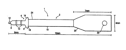
Fig. 1 is a side view of the resorbable pin system.
Fig. 2 is a side view of the resorbable pin system shown after insertion into
a bone
structure and before removal of the handle portion.
DESCRIPTION OF THE PREFERRED EMBODIMENTS
Reference will now be made in detail to the presently preferred embodiments of
the
invention, an example of which is illustrated in the accompanying drawings. In
accordance with the invention, the bioresorbable pin system includes a pin
having a head
and a shank that can be secured within a preformed aperture in a bone, and a
handle having
a shaft and a tip or gripping portion that can be used to insert the pin into
the aperture.
Fig. 1 show a preferred embodiment of the pin system (1) according to the
present
invention, which comprises an elongated handle portion (2) and a pin portion
(4). The pin
portion (4) further comprises a head (6) and a shank (8), the shank preferably
having
compressible ridges (10) and a point (12). The ridges (10) provide a press fit
for the pin as
it is inserted into a pre-drilled aperture in a bone. Cement or other bonding
agent may be
utilized in lieu of, or in addition to, the ridges to anchor the pin in a
bone.
The handle portion (2) of the system further comprises a shaft ( 18) with a
tip or
gripping portion (20). Tip (20) is preferably large enough to be readily
grasped between
the finger tips of the user to permit the user to insert the point (12) and
shank (8) of the pin
portion (4) through a membrane or bone fragment and securely into a pre-formed
aperture
in a bone (as shown in Fig. 2). Rather than forming the entire shaft with the
same
thickness as the tip, most of the shaft is thinner. This facilitates severing
the shaft after the
pin portion has been inserted. In the illustrated embodiment, the shaft and
tip are
CA 02323563 2000-09-12
WO 00/41636 PC'T/US00/00809
_7_
cylindrical, with a conical transition between the two cylindrical portions.
However, other
profiles would be suitable, including a tip portion that is flattened (e.g.,
that has a
thickness equal to the diameter of the shaft but a greater width).
Additionally, the shaft
may be scored or partially cut-through, or otherwise configured, to facilitate
cutting the
S shaft or breaking the shaft using finger pressure, thereby obviating the
need for additional
instrumentation to sever the handle portion from the pin portion.
The head (6) of the pin is relatively flat, has a greater diameter than the
shank (8)
of the pin and has a pin-side face (14) and a handle-side face (16). The pin
side face (14)
is configured to bear against, and provides a compressive force to, the
membrane or bony
fragment to be fixed to the underlying bone. It is preferred that the head
protrude above
the surface of the membrane or bony fragment as little as possible to avoid
irritation of
surrounding tissue. The head is therefore dimensioned with the minimum
thickness
required to sustain the desired compressive loads (in the illustrated
embodiment,
approximately 0.5 mm). This design criterion is therefore contrary to systems
in which the
head provides an anchoring function for other structure, such as the dental
restoration as
shown in U.S. Patent No. 5,263,996. The pin-side face (14) of the pin (4) is
thus capable
of fixing, e.g., a bioresorbable membrane to a bone or fixing a bony fragment
to an
underlying bone.
In use, the pin (4) of resorbable pin system ( 1 ) is inserted through a hole
or other
opening in a bioresorbable membrane or bony fragment (30) into a predrilled
aperture (34)
in underlying bone (32) adjacent to the bone defect to be treated (not shown).
The pin (4)
may be held in place by the frictional forces between bone (32) and the ridges
(10).
Alternatively, or additionally, a bonding agent or other fixative may be used
to further
fasten the pin (4) into the aperture. After an appropriate period of time for
the bonding
agent, if used, to cure, the shaft (18) may be sheared or cut proximal to the
handle-side
face (16) of the head (6) in the vicinity of the proximal portion (24) of the
shaft (18).
Conventional side-cutting pliers or a dental drill may be used for such
shearing or cutting.
In a preferred embodiment of the present invention, the bioresorbable pin
system
further includes a pre-formed hole (22) in the tip (20) of the handle (2). In
use, a tether
(40), which may be any convenient thread-like material such as dental floss or
wire, may
CA 02323563 2000-09-12
WO 00/41636 PCT/US00/00809
_g_
be inserted through the pre-formed hole (22) before the pin portion is
inserted through a
bioresorbable membrane into a bone. As described, the shaft of the handle may
be severed
in the vicinity of the head of the pin by conventional tools. Thereafter, the
handle portion
of the pin system may be withdrawn, e.g., from a patient's mouth, by
withdrawing the
tether to which the handle portion has been threadably attached.
In a preferred embodiment of the present invention, the pin portion and handle
portions are formed as a unitary device and are made of the same polymer
composition.
As illustrated in Fig. 1, the shank of the pin is approximately 3.0 mm in
length and the
head of the pin is about 0.5 mm in thickness (measured along the axis of the
pin). The
shaft of the handle portion is about 8.0 mm and the tip portion of the handle
is about 7.0
mm in length. The diameter of the shank of the pin is about 0.8 mm and the
ridges on the
shank are about 1.0 mm in diameter. The head of the pin is about 2.0 mm in
diameter, and
the diameter of the tip is about 4.0 mm, tapering down to about 2.0 mm where
the tip
meets the shaft.
The bioresorbable pin system of the present invention may be formulated of any
composition known in the art as being appropriate for reabsorption. However,
the
formulation utilized must be sufficiently strong to allow the pin to be
pressed into pre-
drilled holes. A preferred formulation is 70:30 poly(L, DL-lactide). Other
bioresorbable
formulations are known in the art.
It will be apparent to those skilled in the art that various modifications and
variations can be made in the geometry and dimensions of the pin of the
present invention
and in construction of this bioresorbable pin system without departing from
the scope or
spirit of the invention. For example, the length and diameter of the shank and
the diameter
and thickness of the head may be varied to suit different applications, e.g.,
different
thicknesses of membranes or bony fragments to be fixed to the underlying bone.
The
number, profile, position, and dimensions of ridges may be varied, and the
handle may be
scored in the vicinity of the head of the pin to facilitate severing the
handle from the pin.
Other embodiments of the invention will be apparent to those skilled in the
art
from consideration of the specification and practice of the invention
disclosed herein. It is
CA 02323563 2000-09-12
WO 00/41636 PCT/US00/00809
-9-
intended that the specification and examples be considered as exemplary only,
with a true
scope and spirit of the invention being indicated by the following claims.