Language selection

Search

Patent 2323868 Summary

Third-party information liability

Some of the information on this Web page has been provided by external sources. The Government of Canada is not responsible for the accuracy, reliability or currency of the information supplied by external sources. Users wishing to rely upon this information should consult directly with the source of the information. Content provided by external sources is not subject to official languages, privacy and accessibility requirements.

Claims and Abstract availability

Any discrepancies in the text and image of the Claims and Abstract are due to differing posting times. Text of the Claims and Abstract are posted:

  • At the time the application is open to public inspection;
  • At the time of issue of the patent (grant).
(12) Patent Application: (11) CA 2323868
(54) English Title: DEFROSTING DEVICE, IN PARTICULAR FOR REFRIGERATION SYSTEMS
(54) French Title: DISPOSITIF DE DEGIVRAGE DESTINE PARTICULIEREMENT AUX SYSTEMES DE REFRIGERATION
Status: Deemed Abandoned and Beyond the Period of Reinstatement - Pending Response to Notice of Disregarded Communication
Bibliographic Data
(51) International Patent Classification (IPC):
  • F25D 21/02 (2006.01)
(72) Inventors :
  • BURATTI, MAURIZIO (Italy)
  • FIORENTINI, ANTONIO (Italy)
(73) Owners :
  • I.R.C.A. S.P.A. - INDUSTRIA RESISTENZE CORAZZATE E AFFINI
(71) Applicants :
  • I.R.C.A. S.P.A. - INDUSTRIA RESISTENZE CORAZZATE E AFFINI (Italy)
(74) Agent: ROBIC AGENCE PI S.E.C./ROBIC IP AGENCY LP
(74) Associate agent:
(45) Issued:
(86) PCT Filing Date: 1999-02-25
(87) Open to Public Inspection: 1999-09-23
Availability of licence: N/A
Dedicated to the Public: N/A
(25) Language of filing: English

Patent Cooperation Treaty (PCT): Yes
(86) PCT Filing Number: PCT/EP1999/001227
(87) International Publication Number: WO 1999047870
(85) National Entry: 2000-09-12

(30) Application Priority Data:
Application No. Country/Territory Date
VE98A000013 (Italy) 1998-03-19

Abstracts

English Abstract


A device for defrosting the finned cooling assembly (17) of a refrigeration
system, characterised by comprising: an ellipsoid (2, 26) of transparent
polymer materiel housing a light source (6, 32) positioned substantially in
correspondences with one of the focal points, and a sensor (12, 30) for the
light beam radiated by said source and reflected by the inner surface of the
ellipsoid, a plurality of heating and defrosting elements (18) for the finned
cooling assembly (17), which are activated by a signal emitted by the sensor
(12, 30) when this senses a variation in the luminous intensity of the beam,
said variation in luminous intensity of the beam being caused by the formation
of frost along the path of the light beam.


French Abstract

La présente invention concerne un dispositif de dégivrage de l'ensemble de refroidissement à ailette (17) d'un système de réfrigération, caractérisé en ce qu'il contient: (a) un ellipsoïde (2, 26) en matière polymère transparente contenant une source lumineuse (6, 32) placée sensiblement en correspondances avec un des points focaux, et un détecteur (12, 30) de faisceaux lumineux émis par ladite source et réfléchis sur la surface interne de l'ellipsoïde, (b) plusieurs éléments de chauffage et de dégivrage (18) conçus pour l'ensemble de refroidissement (17), qui sont activés par un signal émis par un détecteur (12, 30) lorsqu'il détecte une variation de l'intensité lumineuse d'un faisceau, provoquée par la formation de gel le long du trajet du faisceau lumineux.

Claims

Note: Claims are shown in the official language in which they were submitted.

-7-
CLAIMS
1. A device for defrosting the finned cooling assembly (17) of a
refrigeration system, characterised by comprising:
- an ellipsoid (2,26) of transparent polymer material housing a light source
(6,32) positioned substantially in correspondences with one of the focal
points, and a sensor (12,30) for the light beam radiated by said source and
reflected by the inner surface of the ellipsoid,
- a plurality of heating and defrosting elements (18) for the finned cooling
assembly (17), which are activated by a signal emitted by the sensor
(12,30) when this senses a variation in the luminous intensity of the beam,
said variation in luminous intensity of the beam being caused by the
formation of frost along the path of the light beam.
2. A device as claimed in claim 1, characterised in that said ellipsoid (2)
has a refractive index to air and an eccentricity such that if frost is absent
the
rays emitted by the light source (6) are reflected directly onto the
photodetector (12), whereas if frost is present said rays are refracted so
that
the photodetector senses a variation in luminous intensity.
3. A device as claimed in claim 2, characterised in that said ellipsoid has a
refractive index of 1.49 and an eccentricity of between 0.4 and 0.75.
4. A device as claimed in claim 2, characterised in that said ellipsoid is
provided with a conducting tube (20) thermally connected to the heating
elements (18), so that activation of said elements (18) also causes the frost
on the ellipsoid surface to melt.
5. A device as claimed in claim 1, characterised in that said ellipsoid (2)
has a metallized outer surface and comprises, in correspondence with the
other focal point, a black body which following the formation of frost
interferes

-8-
with the rays radiated by light source, to feed them to the photodetector via
an
optical system (42).
6. A device as claimed in claim 5, characterised in that said black body
consists of a needle with its tip positioned in correspondence with the focal
point and with its other end in contact with the finned assembly.

Description

Note: Descriptions are shown in the official language in which they were submitted.


CA 02323868 2000-09-12
WO 99/47870 PCT/EP99/01227
DEFROSTING DEVICE, IN PARTICULAR FOR REFRIGERATION SYSTEMS
This invention relates to a defrosting device, in particular for
refrigeration systems.
In refrigeration units, the finned assembly is defrosted by the use of
heating elements in contact with the assembly itself. Said heating elements
are in the form of electrical resistance elements, which are powered at
predetermined time intervals for a constant period. If excessive heating
occurs, a safety thermostat ensures that the items contained in the
refrigeration unit remain preserved, by deactivating the heating elements.
This known defrosting system has the drawback of non-optimum
defrosting of the finned because the powering of the heating elements is not
correlated with the effective presence of frost. This can result in:
- activation of the heating elements even if frost is not present on the
finned
assembly, with consequent energy consumption and increase in the
temperature of the environment, resulting in damage to the food,
- inefficient heat transfer by the refrigeration assembly due to the presence
of
frost because of delay in operation of the heating elements.
This drawback is eliminated according to the invention by a device for
defrosting the finned cooling assembly of a refrigeration system as described
in claim 1.
A preferred embodiment of the present invention and one modification
thereof are described in detail hereinafter by way of non-limiting example
with
reference to the accompanying drawings, in which:
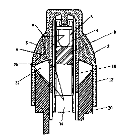
Figure 1 is a schematic view of a first embodiment of the device of the
invention,
Figure 2 shows it mounted on the finned assembly, and

CA 02323868 2000-09-12
WO 99/47870 PCT/EP99/01227
-2-
Figure 3 shows a modification thereof.
As can be seen from the figures the device of the invention consists of
an ellipsoid portion 2, of eccentricity between 0.4 and 0.75, constructed of
transparent polymer (for example polypentenes, PMMA, water-saturated
transparent polyamides, etc.) having a refractive index to air of about 1.49.
Within the ellipsoid 2 there is provided a seat 4 housing a light emitting
diode 6 (preferably a 940 nm IRED) positioned preferably in proximity to a
focal point of the ellipsoid. The diode seat 4 is closed by a plug 8 of black
plastic. Said ellipsoid portion is prolonged in the form of two concentric
tubes
10,12, in one of which, namely in the inner tube 10, there is housed a
photodetector 14 connected to a control unit for an electrical resistance
element 16 mounted on a bracket 18 facing the finned assembly 17 of the
refrigeration unit 19.
In particular, said photodetector is positioned substantially in
correspondence with the other focal point of the ellipsoid.
In the annular compartment bounded by the two tubes 10,12 there is
housed a copper tube 20 having that end surtace facing the ellipsoid
substantially inclined to the tube axis so as to define with the ellipsoid an
annular aperture 22 having two walls formed by portions of the tubes 10,12,
one wall formed by the copper tube 20, and one wall 24 formed by the body of
the ellipsoid itself.
That end of the copper tube external to the ellipsoid is rigid with the
bracket 18, so as to achieve good thermal contact.
The device of the invention operates in the following manner: when
frost is absent, because of the geometrical characteristics of the ellipsoid
the
light rays leaving the diode 6 strike a region of the ellipsoid surface 5 with
an

CA 02323868 2000-09-12
WO 99/47870 PCT/EP99/01227
-3-
angle of incidence (>43°) which is greater than the limiting angle
corresponding to the refractive index of the ellipsoid to air. Consequently
the
rays r are not refracted, but instead are reflected within the ellipsoid
itself, to
then emerge therefrom through the annular band 24 which Pies substantially
perpendicular to the rays. The light rays then interfere with the inner
annular
portion of the tube 10, to undergo double refraction and be conveyed onto the
photodetector 12, which consequently receives all the light rays emitted by
the
diode onto the surface S.
In this configuration, in which the intensity of the radiation received by
the photodetector is a maximum, the resistance element 16 is not powered.
At that moment in which, during the operation of the refrigeration unit,
frost microcrystals form on the outer surface of the ellipsoid, the refractive
index of the ellipsoid to said microcystals covering it varies by virtue of
the
presence of these covering microcystais. As this refractive index decreases,
with consequent increase in the limiting angle corresponding to the new
refractive index, the rays radiated by the diode and which strike this region
are
no longer reflected, but instead are refracted with consequent isotropic light
diffusion to the outside.
This situation consequently results in a decrease in the luminous
intensity of the rays sensed by the photodetector. Moreover the presence of
frost on the annular surface 24 causes a maked defocusing of the beam,
contributing to accelerating the extinguishing of the light beam received by
the
photodetector. Consequently the photodetector feeds a different signal to the
control unit, which compares it with the basic signal previously received when
all the rays struck the photodetector, the control unit causing the resistance

CA 02323868 2000-09-12
WO 99/47870 PCT/EP99/01227
-4-
element 16 to operate when the ratio of the attenuated signal to the basic
signal reaches the order of 50%.
The activation of the resistance element 16 results both in the
defrosting of the finned assembly 17 and, by virtue of the heat conducted
through the bracket 18 and the annular tube 10, the defrosting of the outer
surface of the ellipsoid body, which consequently returns to its initial state
in
which the photodetector 12 receives virtually all the rays transmitted by the
diode. The control unit consequently receives a signal substantially similar
to
the basic signal, to consequently deactivate the resistance element.
In the embodiment shown in Figure 3, the device of the invention
consists substantially of a truncated portion of ellipsoid 26, also of
transparent
polymer material but with its outer surface 5 metalized. Along the major axis
of the portion there is provided a seat 28 housing a photodetector 30, and a
light source 32 in the form of an LED positioned substantially in
correspondence with the focal point of the ellipsoid.
A black mask 34 is interposed between the light source 32 and the
photodetector 30 so that the rays emitted by this source cannot directly
strike
the photodetector.
External to the ellipsoid, in correspondence with its substantially
circular surface 36, there is provided a metal needle 38 with its burnished
mirror-like tip positioned to correspond with the position which would have
corresponded with the other focal point of the ellipsoid if this had not been
truncated. The other end of the needle is in thermal contact with the finned
assembly 17.
The circular surface 38 and the end surface of the seat 28 are curved
and shaped to form a micro-lens 42.

CA 02323868 2000-09-12
WO 99/47870 PCT/EP99/01227
This embodiment of the device of the invention operates in the
following manner:
under normal conditions the light rays r radiated by the LED 30 are
reflected by the metallized surface of the ellipsoid and fed to the tip of the
needle. When in this configuration the photodetector receives no radiation and
consequently feeds no signal to the control unit for activating the resistance
element. In the same manner the burnished tip 39 generates to radiation
towards the photodetector, even if it interferes with the beam. At that moment
in which, as result of the operation of the refrigeration machine, a layer of
frost
forms on the finned assembly, the thermal connection between the metal
needle 38 and the finned assembly 17 creates the same frost conditions on
the tip 39 as on the finned assembly. The increase in the frost thickness on
the needle causes its frost crystals to interfere with the f fight bean
radiated by
the LED and reflected by the surface S of the ellipsoid, with the formation of
an isotropic light source with conjugate image by the LED primary source,
which via the micro-lens 42 is fed to the photodetector 30, which feeds a
signal to the control unit causing it to activate the resistance element in
order
to defrost the finned assembly 17.
In this case the defrosting of the finned assembly also causes
defrosting of the needle tip. The result is the restoration of normal
conditions
with no radiation received by the photodetector, which feeds a signal to the
control unit to deactivate the resistance element.
From the aforegoing it is apparent that the device presents numerous
advantages, and in particular:
- it provides rapid and effective defrosting of the finned assembly as the
resistance element operates only if frost is present,

CA 02323868 2000-09-12
WO 99/47870 PCT/EP99/01227
-s-
- energy costs are reduced as it operates only when frost is present,
- accurate control is obtained on the basis of the thickness of the frost
present on the distributor.

Representative Drawing
A single figure which represents the drawing illustrating the invention.
Administrative Status

2024-08-01:As part of the Next Generation Patents (NGP) transition, the Canadian Patents Database (CPD) now contains a more detailed Event History, which replicates the Event Log of our new back-office solution.

Please note that "Inactive:" events refers to events no longer in use in our new back-office solution.

For a clearer understanding of the status of the application/patent presented on this page, the site Disclaimer , as well as the definitions for Patent , Event History , Maintenance Fee  and Payment History  should be consulted.

Event History

Description Date
Application Not Reinstated by Deadline 2005-02-25
Time Limit for Reversal Expired 2005-02-25
Inactive: Abandon-RFE+Late fee unpaid-Correspondence sent 2004-02-25
Deemed Abandoned - Failure to Respond to Maintenance Fee Notice 2004-02-25
Letter Sent 2001-04-27
Inactive: Single transfer 2001-03-23
Inactive: Cover page published 2000-12-08
Inactive: First IPC assigned 2000-12-06
Inactive: Courtesy letter - Evidence 2000-12-05
Inactive: Notice - National entry - No RFE 2000-11-30
Application Received - PCT 2000-11-28
Application Published (Open to Public Inspection) 1999-09-23

Abandonment History

Abandonment Date Reason Reinstatement Date
2004-02-25

Maintenance Fee

The last payment was received on 2002-12-16

Note : If the full payment has not been received on or before the date indicated, a further fee may be required which may be one of the following

  • the reinstatement fee;
  • the late payment fee; or
  • additional fee to reverse deemed expiry.

Please refer to the CIPO Patent Fees web page to see all current fee amounts.

Fee History

Fee Type Anniversary Year Due Date Paid Date
Basic national fee - small 2000-09-12
MF (application, 2nd anniv.) - small 02 2001-02-26 2001-02-15
Registration of a document 2001-03-23
MF (application, 3rd anniv.) - small 03 2002-02-25 2002-02-12
MF (application, 4th anniv.) - small 04 2003-02-25 2002-12-16
Owners on Record

Note: Records showing the ownership history in alphabetical order.

Current Owners on Record
I.R.C.A. S.P.A. - INDUSTRIA RESISTENZE CORAZZATE E AFFINI
Past Owners on Record
ANTONIO FIORENTINI
MAURIZIO BURATTI
Past Owners that do not appear in the "Owners on Record" listing will appear in other documentation within the application.
Documents

To view selected files, please enter reCAPTCHA code :


To view images, click a link in the Document Description column. To download the documents, select one or more checkboxes in the first column and then click the "Download Selected in PDF format (Zip Archive)" or the "Download Selected as Single PDF" button.

List of published and non-published patent-specific documents on the CPD .

If you have any difficulty accessing content, you can call the Client Service Centre at 1-866-997-1936 or send them an e-mail at CIPO Client Service Centre.


Document
Description 
Date
(yyyy-mm-dd) 
Number of pages   Size of Image (KB) 
Representative drawing 2000-12-08 1 15
Abstract 2000-09-12 1 72
Description 2000-09-12 6 236
Claims 2000-09-12 2 57
Drawings 2000-09-12 2 65
Cover Page 2000-12-08 1 59
Reminder of maintenance fee due 2000-11-29 1 112
Notice of National Entry 2000-11-30 1 195
Courtesy - Certificate of registration (related document(s)) 2001-04-27 1 113
Reminder - Request for Examination 2003-10-28 1 112
Courtesy - Abandonment Letter (Maintenance Fee) 2004-04-21 1 175
Courtesy - Abandonment Letter (Request for Examination) 2004-05-05 1 167
Correspondence 2000-11-30 1 15
PCT 2000-09-12 9 285
Correspondence 2001-03-23 2 76
Fees 2002-12-16 1 32
Fees 2002-02-12 1 30
Fees 2001-02-15 1 31