Note: Descriptions are shown in the official language in which they were submitted.
CA 02324288 2000-09-07
WO 99/45990 PC"f/AU99/00150
ENDOTRACHEAL TUBE FOR SELECTIVE BRONCHIAL OCCLUSION
TECHNICAL FIELD
The present invention relates to an improved endotracheal tube for selective
bronchial
occlusion for use in medical and surgical procedures in hospitals, and for on-
site post-
trauma medical stabilisation procedures.
BACKGROUND ART
In the event of damage to a lung, such as a collapsed lung following some form
of
trauma, it is often necessary to intubate the lungs with a view to isolating
and occluding
the damaged lung and ventilating the other lung.
Present devices and procedures for achieving this end are, in general, complex
and
require a high level of training and skill for accurate and effective
placement. For
example, with some patients, it may take the anaesthetist or surgeon up to one
hour to
occlude a collapsed lung and to ensure correct placement and intubation of the
remaining
functioning lung. Quite often anaesthetists lack the training or skills to
ensure correct
lung intubation/occlusion, and this procedure is left to the surgeon to
perform.
In the case of paramedics, such as ambulance personnel, instigating primary
stabilisation
and treatment of traumatised patients at, for example, the scene of an
accident, such
paramedics lack the skills to correctly intubate and ventilate a patient with
a damaged
lung using existing medical equipment and procedures.
DISCLOSURE OF THE INVENTION
It is an object of this invention to provide an improved endotracheal tube for
medical
intubation which goes at least some way towards overcoming or at least
minimising the
prior art problems or limitations outlined above, and for providing a clear
alternative
choice for use by medical personnel.
SUBSTIT'ITTE SHEET (Rule 26) (RO/AU)
CA 02324288 2000-09-07
PCT/AU99/00150
Received O1 Feb 2000
2
It is another object of this invention to provide an endotracheal tube for
medical
intubation which provides for selective bronchial occlusion and ventilation of
the lungs.
It is a further object of this invention to provide an endotracheal tube
including means for
easier or simpler selection of, and placement in, left or right bronchii.
It is yet another object of this invention to provide an improved endotracheal
tube for
selective bronchial occlusion/placement which is relatively simple to operate,
and is
suitable for use by both medical and paramedical personnel with minimal
training and/or
supervision.
These and other objects of the present invention will become more apparent
from the
following descriptions and drawings.
According to one aspect of the present invention, there is provided an
endotracheal tube
for selective bronchial occlusion and/or placement for lung ventilation of a
patient,
comprising an elongate, flexible bronchial/tracheal tube having a central
channel or
lumen extending throughout its entire length with an opening at each of
opposed distal
and proximal ends thereof, the opening at the proximal end of the tube being
adapted for
connection to a ventilation device and the opening at the distal end
comprising a first or
distal air vent for venting air into the lungs of a patient, said
bronchial/tracheal tube
having separate spaced apart distal and proximal peripherally inflatable
portions at the
distal end of the tube and at a proximal location relative thereto,
respectively, and a
second or proximal air vent opening in the sidewall of that portion of the
tube extending
between said distal and proximal inflatable portions thereof, wherein in situ
said distal
inflatable portion is inflatable both radially outwardly adapted to seal
against the
surrounding bronchus connected to one of the lungs and radially inwardly to
seal against
itself to occlude the lumen of the tube and thereby effectively occlude the
lung, wherein
said proximal inflatable portion is inflatable radially outwardly adapted to
seal against the
surrounding trachea of the patient, and whereby an airway to the patient's
other lung is
maintained via the said second or proximal air vent opening.
AME~1~E~ SHEET
w~E~r,~u
CA 02324288 2000-09-07
WO 99/45990 PCT/AU99/00150
3
Ideally, the endotracheal tube comprises separate means for inflating the
distal and
proximal peripherally inflatable portions thereof, as well as separate fibre
optic and
suction means operative at the distal end of the tube to assist with placement
of the tube
into the left or right bronchii and or for draining air or fluids from the
lung.
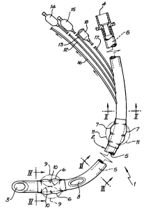
BRIEF DESCRIPTION OF THE ACCOMPANYING DRAWINGS
The invention will now be further described with reference to the accompanying
drawings
relating to one possible non-limiting embodiment of the invention. In the
drawings:-
FIG. 1 is a partially cut-away elevation of an endotracheal tube according
to this embodiment of the invention;
FIG. 2 is a cross-sectional view of the tube of Fig. l taken along the line
II-II of Fig. 1;
FIG. 3 is a further cross-sectional view of the tube of Fig. l taken along the
line III-III of Fig. 1; and
FIG. 4 represents another cross-sectional view of the tube of Fig. 1 taken
along
the line IV-IV of Fig. 1.
BEST MODE OF CARRYING OUT THE INVENTION
According to the embodiment as illustrated in Fig.1, the endotracheal tube 1
comprises
an elongate flexible bronchial/tracheal tube 2, having an open distal end 3
and an open
proximal end 4 joined by an elongate central channel or lumen 5.
The endotracheal tube 1 has separate spaced-apart distal and proximal
peripherally
inflatable portions, 6 and 7 respectively, towards the distal end 3 of the
tube, with an
opening 8 in the peripheral sidewall of the tube. The distal inflatable
portion 6 is
inflatable peripherally both radially outwardly (as shown at 9) and radially
inwardly (as at
SUBSTTTU'TE SHEET (Rule 26) (RO/AL~
CA 02324288 2000-09-07
WO 99/45990 PCT/AU99/00150
4
10). The proximal inflatable portion 7 is inflatable peripherally radially
outwardly only
(as shown at 11).
Separate inflation means 12 and 13 are provided for inflation of the distal
balloon 6 and
the proximal balloon 7, respectively, comprising in each case elongate tubing
extending
externally from points adjacent the proximal end 4 of the endotracheal tube 1
and then
peripherally and longitudinally within the sidewall of the tube 1, best seen
in cross-
section in Figs 2, 3 and 4, towards the inflatable balloons 6 and 7. An
inflatable bladder
(14 and 15), with a one-way non-return valve, is provided at the proximal ends
of each
tube 12 and 13, respectively. Each of inflatable balloons 6 and 7, is adapted
to be inflated
in use as and when required by attachment of a syringe at the bladder end 14
and 15 of
the tubing 12 and 13 and injecting a predetermined quantity of air. Inflation
of the
balloons 6 and 7, in vivo, is indicated by inflation of the corresponding
bladders 14 and
15, respectively.
Optionally, but preferably, a distal end suction tube 16 is provided for
draining air or
fluid from the lungs insitu. Likewise, it is preferred that the endotracheal
tube includes
re-useable fibre optic means 17, extending from the distal end 3 to the
proximal end 4, to
assist with placement of the tube 1 insitu. The inclusion of the tubes
12,13,16 and 17 in
the peripheral sidewail of the bronchial/tracheal tube 2 is best demonstrated
in the cross-
sections thereof at positions II-II, III-III and IV-IV, as illustrated in
Figs. 2, 3 and 4,
respectively .
The components of the endotracheal tube are fabricated from plastics materials
which are
conventionally used in medical and surgical applications.
In use, the endotracheal tube 1 is guided into the bronchus of the lung to be
occluded for,
say, surgical repair (e.g. the right lung) by means of the optical fibre
viewing device 18
which provides visual direction or guidance of the distal end 3 of the
endotracheal tube
via optic fibre 17. When the distal end of the tube is correctly located in
the bronchus of
the right lung, the distal balloon 6 is inflated by injecting air via a
syringe into the bladder
SUBSTITUTE SHEET (Rule 26) (RO/AU)
CA 02324288 2000-09-07
WO 99/45990 PCT/AU99/00150
end 14 of the elongate tube 12. Inflation of the bladder 14 indicates that the
balloon 6 is
inflated insitu, thus occluding the bronchus to the right lung. Air and
secretions from the
right lung can be drained therefrom by means of suction tube 16.
Inflation of balloon 7 by means of air injected via bladder 15 and tubing 13
results in
occlusion of the bronchial tube surrounding the inflated balloon 7. The left
lung can then
be ventilated via the ventilation opening 8 in the sidewall of the
endotracheal tube 1
which is in operative communication via lumen S with the ventilation means at
the
proximal end 4 of the tube. The inflated balloons 6 and 7 isolate those
sections of the
bronchial tube below balloon 6 and above balloon 7, completely occluding the
right lung
but allowing the left lung to work normally. Surgical repair of the occluded
right lung is
now possible.
The endotracheal tube is removed by first deflating the balloons 6 and 7 by
releasing air
from the bladder ends 14 and 15, and then withdrawing the endotracheal tube.
Although an exemplary embodiment of the present invention has been described
and
illustrated, it will be apparent to those having ordinary skill in the art
that a number of
changes, modifications or alterations to the invention described herein may be
made,
none of which depart from the spirit of the present invention. All such
changes,
modifications and alterations should therefore be seen as being within the
scope of the
present invention.
It should be appreciated that the present invention provides a substantial
advance in
endotracheal tubes for selective bronchial occlusion, providing all of the
hereindescribed
advantages without incurring any relative disadvantages.
SUBSTITUTE SHEET (Rule 26) (RO/AU)