Language selection

Search

Patent 2324579 Summary

Third-party information liability

Some of the information on this Web page has been provided by external sources. The Government of Canada is not responsible for the accuracy, reliability or currency of the information supplied by external sources. Users wishing to rely upon this information should consult directly with the source of the information. Content provided by external sources is not subject to official languages, privacy and accessibility requirements.

Claims and Abstract availability

Any discrepancies in the text and image of the Claims and Abstract are due to differing posting times. Text of the Claims and Abstract are posted:

  • At the time the application is open to public inspection;
  • At the time of issue of the patent (grant).
(12) Patent Application: (11) CA 2324579
(54) English Title: WOOD WORKING MACHINE
(54) French Title: MACHINE A BOIS
Status: Deemed Abandoned and Beyond the Period of Reinstatement - Pending Response to Notice of Disregarded Communication
Bibliographic Data
(51) International Patent Classification (IPC):
  • B27L 01/02 (2006.01)
  • B27L 01/10 (2006.01)
(72) Inventors :
  • OLEDAL, JAN (Sweden)
  • SVENSSON, AKE (Sweden)
(73) Owners :
  • HFD HALF PIPE DEBARKER AB
(71) Applicants :
  • HFD HALF PIPE DEBARKER AB (Sweden)
(74) Agent: GOWLING WLG (CANADA) LLP
(74) Associate agent:
(45) Issued:
(86) PCT Filing Date: 1999-03-17
(87) Open to Public Inspection: 1999-09-30
Examination requested: 2003-11-07
Availability of licence: N/A
Dedicated to the Public: N/A
(25) Language of filing: English

Patent Cooperation Treaty (PCT): Yes
(86) PCT Filing Number: PCT/SE1999/000412
(87) International Publication Number: SE1999000412
(85) National Entry: 2000-09-19

(30) Application Priority Data:
Application No. Country/Territory Date
9800926-9 (Sweden) 1998-03-20

Abstracts

English Abstract


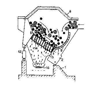
This invention relates to a method for working wood like pulp wood, saw timber
or similar elongated wood parts, a working machine being at hand, which
comprises a trough designed like a tunnel, which trough has a feeding in end
and a feeding out end for the wood and in which are arranged a plurality of
rotors, provided with means on its jacketsurface, the purpose of which is to
debark the wood at least partially. According to the invention the method is
characterized by the combination of following steps: the wood during the
working is taken by the rotors (6) from a portion of the trough (2) on a first
level to a side-displaced portion of the trough on a second, higher level,
wherefrom the wood falls down to the lower level, whereby tumbling of the wood
is brought about at the same time as a further working of the wood can be
made; the wood during the working is taken by the rotors from the feeding in
end (3) of the trough (2) to its feeding out end (4). The invention also
relates to a working machine for carrying out the method.


French Abstract

L'invention concerne un procédé servant à travailler du bois, tel que du bois de pâte à papier, du bois de sciage ou des pièces de bois allongées de ce type, ainsi qu'une machine à bois comprenant une goulotte sous forme de tunnel possédant une extrémité d'alimentation et une extrémité d'évacuation, dans laquelle sont disposés une pluralité de rotors et dont l'enveloppe présente en surface des moyens servant à écorcer le bois au moins partiellement. Ce procédé consiste en la combinaison des étapes suivantes: le bois est saisi par les rotors (6) depuis une partie de la goulotte (2) sur un premier niveau jusqu'à une partie décalée latéralement de la goulotte sur un deuxième niveau supérieur, depuis lequel le bois tombe vers le niveau inférieur, ce qui provoque le basculement du bois simultanément au déclenchement de la continuation du processus de travail; pendant ce dernier, le bois est saisi par les rotors depuis l'extrémité d'alimentation (3) de la goulotte (2) jusqu'à son extrémité d'évacuation (4). L'invention concerne également une machine à bois servant à mettre ce procédé en application.

Claims

Note: Claims are shown in the official language in which they were submitted.


1
Claims
1. A machine for working wood like pulp wood, saw timber or similar
elongated wood parts, the machine comprising a trough which has a feeding in
end
and a feeding out end for the wood, and in which are arranged a plurality of
rotors
provided with means on its jacket surface, the purpose of which is to debark
the
wood at least partially,
wherein the rotors (6) have such a position that their longitudinal direction
forms an angle with a transverse horizontal line through the machine and are
designed with helical threads on its jacket surface, characterized by the
following features:
- The trough (2) is designed in that way that the wood is fed into the same on
a first, low level, whereas the feeding out from the through (2) is made on a
second,
higher level, i.e. the longitudinal centre line through the trough is inclined
upwards,
seen from the feeding in end;
- The rotors (6) are arranged in that way that the angle between the length
axis
of the rotors and the longitudinal direction of the trough is less than
90°, i.e. the axis
of the rotors are inclined backwards, seen in the transporting direction;
- The trough (2) is designed in that way that it is steplessly pivotable about
a
shaft (11), which is parallel with the longitudinal direction of the trough,
which
means that the trough can take different angle positions in relation to a
transverse
horizontal line through the machine, and which also means that the angle
between the
longitudinal direction of the rotors (6) and the transverse horizontal line
through the
machine can be steplessly changed.
2. A machine according to claim 1, characterized in that the trough
(2) is provided with an openable cover (8) at its upper part for reduction of
dust and
noise.

Description

Note: Descriptions are shown in the official language in which they were submitted.


CA 02324579 2000-09-19
WO 99/48657 PCT/SE99/00412
1
WOOD WORKING MACHINE
This invention relates to a method for working wood like pulp wood,
sawtimber or similar elongated wood parts, a working machine being at hand,
which
comprises a trough designed like a tunnel, which trough has a feeding in end
and a
feeding out end for the wood and in which are arranged a plurality of rotors,
provided
with means on its jacket surface, the purpose of which is to debark at least
partially of
the wood.
The invention also relates to a working machine for carrying out the
method.
Machines are previously known which have been designed with
longitudinal rotors with strong heels, intended to work the bark of the wood.
In order
that the machine shall function satisfactory, it has been designed in that way
that the
feeding in end of the trough has been placed essentially higher than its
feeding out
end. Due to that fact, the transport of the wood through the machine has been
made on
a downward slope. This fact regarding the position of the trough means partly
that the
wood has to be lifted to a high position at the feeding in end, partly to be
lifted up a
good distance at the feeding out end in order to be able to be smoothly fed
into a
following chipper, saw station or the like.
Another drawback with the known machine is that the mentioned rotor
heels work the wood across the fibre direction, whereby wood damages and fibre
losses become great.
The purpose with the present invention is to bring about an adjustable,
lenient working of the wood, which makes the treatment of wood, which is hard
to
work as well as easy to work possible. Furthermore, the transport through the
trough
from its feeding in end to its feeding out end is preferably made on an.
upward slope,
i.e. a longitudinal centre line through the trough from the feeding in end to
its feeding
out end inclines upwards. Due to that fact, the feeding of the wood into the
trough is
made on a low level and the feeding out to a following working station, for
instance a
chipper, is made an a relatively high level.
This purposes have been achieved by the fact that the invention has got
the features mentioned in the claims.

CA 02324579 2000-09-19
WO 99/48657 PCT/SE99/00412
2
A preferred embodiment of the invention shall be described more closely
below with reference to the accompanying drawings, where Fig. la shows the
wood
working machine from the side, Fig. lb shows the machine from above, Fig. 2
shows
a part of a longitudinal section, taken in parallel with the upperside of the
rotors, and
Fig. 3 shows a section through the machine, taken along the line III-III in
fig. lb.
With reference to the drawings is shown there the wood working
machine, which has' a trough 2 in the form of a tunnel which is articulately
suspended
in a frame 1, the trough having a feeding in end 3, and a feeding out end 4
for the
wood. At the feeding in end 3 there is a feeding in opening 5 for the wood.
The
trough 2 has a great number of helical rotors 6 (see figs. 2, 3} at its lower
part 7 and
is provided with an openable cover 8 at its upper part in front of the feeding
in
opening 5 for reduction of dust and noise. Over the feeding in opening S
itself there is
no cover, whether fixed or openable. Due to that fact, the feeding of wood
into the
trough is facilitated. A side portion of the trough has a suitably designed
wall 9.
The helical rotors 6, the one and of which is connected to the lower
portion 10 of the wall 9 is provided with means and are inclined upwards in
the
direction from the lower portion 10 of the wall 9. This inclination of the
helical rotors
6 are steplessly adjustable by the fact that the trough 2 can be steplessly
pivoted about
a suspension point 11, which can be a shaft, that is parallel with the
longitudinal
direction of the trough, by means of far instance a piston cylinder 12 or a
screw jack.
This means that the trough 2 can take different angle positions in relation to
a
transverse, horizontal line, drawn through the machine.
The helical rotors 6 are provided with screw threads 13 on its jacket
surface. This fact plus the fact that the rotors are obliquely positioned in
relation to a
transverse line through the machine make possible that the wood falls down
between
the threads and are given a movement from below and upwards (see fig. 3) at
the
same time as a debarking of the wood is made. At least certain parts of the
screw
threads are provided with flails 14 or similar means, which are intended to
damage the
bark, whereby the debarking is made more effective.
According to a preferred embodiment the helical rotors 6 are driven by
one or more electric motors and have a length of about 2 m. The rotors 6 have
a
diameter of 600 mm and a pitch of about 800 mm. The rotors 6 are further
arranged

CA 02324579 2000-09-19
WO 99/48657 PCT/SE99/00412
with an initial inclination so that they by means of the lifting cylinder can
take an
angle position in relation to the transverse horizontal line between
25° and 45°.
For collection of bark and wastage is a conveyer 15 arranged under the
wood working machine.
The wood working machine functions in that way that when wood in
bundles or continuously is laid down into the trough 2 of the machine, it is
influenced
by the threads 13 of the helical rotors 6 so that it is lifted up and begins
to rotate
(tumble) in the trough 2 at the same time as it is driven upwards. Due to that
fact,
worked wood from its uppermost position will fall back to the bottom portion
of the
trough and once again begin to be worked. During the rotation of the rotors 6,
the
wood will not only be lifted upwards but of course be brought forwards towards
the
feeding out end 4 of the trough.
When continuously feeding wood in bundles into the trough, the
tumbling will even out the wood to a continuous wood string which under a
continuous tumbling is transported through the machine with a velocity which
depends
on the adjusted inclination of the rotors. Due to that fact, the degree of
working can
be adapted to the need, since the residence time of the wood in the machine is
on the
whole controlled by the inclination.
Due to special design of the rotors and the position of these ones, the
great advantage is achieved that the debarking is made along the wood and not
in its
transverse direction. Due to that fact the debarking becomes lenient to the
wood.
The invention is of course not limited to the mentioned and shown
embodiment but can be modified within the scope of the following claims.

Representative Drawing
A single figure which represents the drawing illustrating the invention.
Administrative Status

2024-08-01:As part of the Next Generation Patents (NGP) transition, the Canadian Patents Database (CPD) now contains a more detailed Event History, which replicates the Event Log of our new back-office solution.

Please note that "Inactive:" events refers to events no longer in use in our new back-office solution.

For a clearer understanding of the status of the application/patent presented on this page, the site Disclaimer , as well as the definitions for Patent , Event History , Maintenance Fee  and Payment History  should be consulted.

Event History

Description Date
Application Not Reinstated by Deadline 2007-03-19
Time Limit for Reversal Expired 2007-03-19
Inactive: Abandoned - No reply to s.30(2) Rules requisition 2006-03-20
Deemed Abandoned - Failure to Respond to Maintenance Fee Notice 2006-03-17
Inactive: IPC from MCD 2006-03-12
Inactive: S.30(2) Rules - Examiner requisition 2005-09-20
Inactive: Entity size changed 2004-04-08
Amendment Received - Voluntary Amendment 2003-12-09
Letter Sent 2003-11-21
Request for Examination Received 2003-11-07
Request for Examination Requirements Determined Compliant 2003-11-07
All Requirements for Examination Determined Compliant 2003-11-07
Inactive: Correspondence - Transfer 2001-11-15
Letter Sent 2001-09-28
Inactive: Single transfer 2001-08-23
Inactive: Notice - National entry - No RFE 2001-02-23
Inactive: Filing certificate correction 2001-01-26
Inactive: Courtesy letter - Evidence 2001-01-11
Inactive: Correspondence - Transfer 2001-01-09
Inactive: Cover page published 2001-01-03
Inactive: First IPC assigned 2000-12-31
Inactive: Courtesy letter - Evidence 2000-12-27
Inactive: Notice - National entry - No RFE 2000-12-20
Application Received - PCT 2000-12-05
Inactive: Single transfer 2000-12-05
Application Published (Open to Public Inspection) 1999-09-30

Abandonment History

Abandonment Date Reason Reinstatement Date
2006-03-17

Maintenance Fee

The last payment was received on 2005-02-21

Note : If the full payment has not been received on or before the date indicated, a further fee may be required which may be one of the following

  • the reinstatement fee;
  • the late payment fee; or
  • additional fee to reverse deemed expiry.

Patent fees are adjusted on the 1st of January every year. The amounts above are the current amounts if received by December 31 of the current year.
Please refer to the CIPO Patent Fees web page to see all current fee amounts.

Fee History

Fee Type Anniversary Year Due Date Paid Date
Registration of a document 2000-09-19
Basic national fee - small 2000-09-19
Registration of a document 2000-12-05
MF (application, 2nd anniv.) - small 02 2001-03-19 2001-02-26
MF (application, 3rd anniv.) - small 03 2002-03-18 2002-03-12
MF (application, 4th anniv.) - small 04 2003-03-17 2003-03-10
Request for examination - small 2003-11-07
MF (application, 5th anniv.) - standard 05 2004-03-17 2004-03-17
MF (application, 6th anniv.) - standard 06 2005-03-17 2005-02-21
Owners on Record

Note: Records showing the ownership history in alphabetical order.

Current Owners on Record
HFD HALF PIPE DEBARKER AB
Past Owners on Record
AKE SVENSSON
JAN OLEDAL
Past Owners that do not appear in the "Owners on Record" listing will appear in other documentation within the application.
Documents

To view selected files, please enter reCAPTCHA code :


To view images, click a link in the Document Description column. To download the documents, select one or more checkboxes in the first column and then click the "Download Selected in PDF format (Zip Archive)" or the "Download Selected as Single PDF" button.

List of published and non-published patent-specific documents on the CPD .

If you have any difficulty accessing content, you can call the Client Service Centre at 1-866-997-1936 or send them an e-mail at CIPO Client Service Centre.


Document
Description 
Date
(yyyy-mm-dd) 
Number of pages   Size of Image (KB) 
Representative drawing 2001-01-02 1 12
Abstract 2000-09-18 1 68
Description 2000-09-18 3 154
Claims 2000-09-18 1 44
Drawings 2000-09-18 2 43
Reminder of maintenance fee due 2000-12-17 1 112
Notice of National Entry 2000-12-19 1 195
Notice of National Entry 2001-02-22 1 194
Request for evidence or missing transfer 2001-09-19 1 111
Courtesy - Certificate of registration (related document(s)) 2001-09-27 1 136
Reminder - Request for Examination 2003-11-17 1 112
Acknowledgement of Request for Examination 2003-11-20 1 188
Courtesy - Abandonment Letter (Maintenance Fee) 2006-05-14 1 177
Courtesy - Abandonment Letter (R30(2)) 2006-05-28 1 166
Correspondence 2000-12-19 1 14
PCT 2000-09-18 11 465
Correspondence 2001-01-10 1 24
Correspondence 2001-01-25 1 27
Fees 2003-03-09 1 31
Fees 2002-03-11 1 35
Fees 2001-02-25 1 25
Fees 2004-03-16 1 32