Sélection de la langue

Search

Sommaire du brevet 2324579 

Énoncé de désistement de responsabilité concernant l'information provenant de tiers

Une partie des informations de ce site Web a été fournie par des sources externes. Le gouvernement du Canada n'assume aucune responsabilité concernant la précision, l'actualité ou la fiabilité des informations fournies par les sources externes. Les utilisateurs qui désirent employer cette information devraient consulter directement la source des informations. Le contenu fourni par les sources externes n'est pas assujetti aux exigences sur les langues officielles, la protection des renseignements personnels et l'accessibilité.

Disponibilité de l'Abrégé et des Revendications

L'apparition de différences dans le texte et l'image des Revendications et de l'Abrégé dépend du moment auquel le document est publié. Les textes des Revendications et de l'Abrégé sont affichés :

  • lorsque la demande peut être examinée par le public;
  • lorsque le brevet est émis (délivrance).
(12) Demande de brevet: (11) CA 2324579
(54) Titre français: MACHINE A BOIS
(54) Titre anglais: WOOD WORKING MACHINE
Statut: Réputée abandonnée et au-delà du délai pour le rétablissement - en attente de la réponse à l’avis de communication rejetée
Données bibliographiques
(51) Classification internationale des brevets (CIB):
  • B27L 01/02 (2006.01)
  • B27L 01/10 (2006.01)
(72) Inventeurs :
  • OLEDAL, JAN (Suède)
  • SVENSSON, AKE (Suède)
(73) Titulaires :
  • HFD HALF PIPE DEBARKER AB
(71) Demandeurs :
  • HFD HALF PIPE DEBARKER AB (Suède)
(74) Agent: GOWLING WLG (CANADA) LLP
(74) Co-agent:
(45) Délivré:
(86) Date de dépôt PCT: 1999-03-17
(87) Mise à la disponibilité du public: 1999-09-30
Requête d'examen: 2003-11-07
Licence disponible: S.O.
Cédé au domaine public: S.O.
(25) Langue des documents déposés: Anglais

Traité de coopération en matière de brevets (PCT): Oui
(86) Numéro de la demande PCT: PCT/SE1999/000412
(87) Numéro de publication internationale PCT: SE1999000412
(85) Entrée nationale: 2000-09-19

(30) Données de priorité de la demande:
Numéro de la demande Pays / territoire Date
9800926-9 (Suède) 1998-03-20

Abrégés

Abrégé français

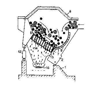
L'invention concerne un procédé servant à travailler du bois, tel que du bois de pâte à papier, du bois de sciage ou des pièces de bois allongées de ce type, ainsi qu'une machine à bois comprenant une goulotte sous forme de tunnel possédant une extrémité d'alimentation et une extrémité d'évacuation, dans laquelle sont disposés une pluralité de rotors et dont l'enveloppe présente en surface des moyens servant à écorcer le bois au moins partiellement. Ce procédé consiste en la combinaison des étapes suivantes: le bois est saisi par les rotors (6) depuis une partie de la goulotte (2) sur un premier niveau jusqu'à une partie décalée latéralement de la goulotte sur un deuxième niveau supérieur, depuis lequel le bois tombe vers le niveau inférieur, ce qui provoque le basculement du bois simultanément au déclenchement de la continuation du processus de travail; pendant ce dernier, le bois est saisi par les rotors depuis l'extrémité d'alimentation (3) de la goulotte (2) jusqu'à son extrémité d'évacuation (4). L'invention concerne également une machine à bois servant à mettre ce procédé en application.


Abrégé anglais


This invention relates to a method for working wood like pulp wood, saw timber
or similar elongated wood parts, a working machine being at hand, which
comprises a trough designed like a tunnel, which trough has a feeding in end
and a feeding out end for the wood and in which are arranged a plurality of
rotors, provided with means on its jacketsurface, the purpose of which is to
debark the wood at least partially. According to the invention the method is
characterized by the combination of following steps: the wood during the
working is taken by the rotors (6) from a portion of the trough (2) on a first
level to a side-displaced portion of the trough on a second, higher level,
wherefrom the wood falls down to the lower level, whereby tumbling of the wood
is brought about at the same time as a further working of the wood can be
made; the wood during the working is taken by the rotors from the feeding in
end (3) of the trough (2) to its feeding out end (4). The invention also
relates to a working machine for carrying out the method.

Revendications

Note : Les revendications sont présentées dans la langue officielle dans laquelle elles ont été soumises.


1
Claims
1. A machine for working wood like pulp wood, saw timber or similar
elongated wood parts, the machine comprising a trough which has a feeding in
end
and a feeding out end for the wood, and in which are arranged a plurality of
rotors
provided with means on its jacket surface, the purpose of which is to debark
the
wood at least partially,
wherein the rotors (6) have such a position that their longitudinal direction
forms an angle with a transverse horizontal line through the machine and are
designed with helical threads on its jacket surface, characterized by the
following features:
- The trough (2) is designed in that way that the wood is fed into the same on
a first, low level, whereas the feeding out from the through (2) is made on a
second,
higher level, i.e. the longitudinal centre line through the trough is inclined
upwards,
seen from the feeding in end;
- The rotors (6) are arranged in that way that the angle between the length
axis
of the rotors and the longitudinal direction of the trough is less than
90°, i.e. the axis
of the rotors are inclined backwards, seen in the transporting direction;
- The trough (2) is designed in that way that it is steplessly pivotable about
a
shaft (11), which is parallel with the longitudinal direction of the trough,
which
means that the trough can take different angle positions in relation to a
transverse
horizontal line through the machine, and which also means that the angle
between the
longitudinal direction of the rotors (6) and the transverse horizontal line
through the
machine can be steplessly changed.
2. A machine according to claim 1, characterized in that the trough
(2) is provided with an openable cover (8) at its upper part for reduction of
dust and
noise.

Description

Note : Les descriptions sont présentées dans la langue officielle dans laquelle elles ont été soumises.


CA 02324579 2000-09-19
WO 99/48657 PCT/SE99/00412
1
WOOD WORKING MACHINE
This invention relates to a method for working wood like pulp wood,
sawtimber or similar elongated wood parts, a working machine being at hand,
which
comprises a trough designed like a tunnel, which trough has a feeding in end
and a
feeding out end for the wood and in which are arranged a plurality of rotors,
provided
with means on its jacket surface, the purpose of which is to debark at least
partially of
the wood.
The invention also relates to a working machine for carrying out the
method.
Machines are previously known which have been designed with
longitudinal rotors with strong heels, intended to work the bark of the wood.
In order
that the machine shall function satisfactory, it has been designed in that way
that the
feeding in end of the trough has been placed essentially higher than its
feeding out
end. Due to that fact, the transport of the wood through the machine has been
made on
a downward slope. This fact regarding the position of the trough means partly
that the
wood has to be lifted to a high position at the feeding in end, partly to be
lifted up a
good distance at the feeding out end in order to be able to be smoothly fed
into a
following chipper, saw station or the like.
Another drawback with the known machine is that the mentioned rotor
heels work the wood across the fibre direction, whereby wood damages and fibre
losses become great.
The purpose with the present invention is to bring about an adjustable,
lenient working of the wood, which makes the treatment of wood, which is hard
to
work as well as easy to work possible. Furthermore, the transport through the
trough
from its feeding in end to its feeding out end is preferably made on an.
upward slope,
i.e. a longitudinal centre line through the trough from the feeding in end to
its feeding
out end inclines upwards. Due to that fact, the feeding of the wood into the
trough is
made on a low level and the feeding out to a following working station, for
instance a
chipper, is made an a relatively high level.
This purposes have been achieved by the fact that the invention has got
the features mentioned in the claims.

CA 02324579 2000-09-19
WO 99/48657 PCT/SE99/00412
2
A preferred embodiment of the invention shall be described more closely
below with reference to the accompanying drawings, where Fig. la shows the
wood
working machine from the side, Fig. lb shows the machine from above, Fig. 2
shows
a part of a longitudinal section, taken in parallel with the upperside of the
rotors, and
Fig. 3 shows a section through the machine, taken along the line III-III in
fig. lb.
With reference to the drawings is shown there the wood working
machine, which has' a trough 2 in the form of a tunnel which is articulately
suspended
in a frame 1, the trough having a feeding in end 3, and a feeding out end 4
for the
wood. At the feeding in end 3 there is a feeding in opening 5 for the wood.
The
trough 2 has a great number of helical rotors 6 (see figs. 2, 3} at its lower
part 7 and
is provided with an openable cover 8 at its upper part in front of the feeding
in
opening 5 for reduction of dust and noise. Over the feeding in opening S
itself there is
no cover, whether fixed or openable. Due to that fact, the feeding of wood
into the
trough is facilitated. A side portion of the trough has a suitably designed
wall 9.
The helical rotors 6, the one and of which is connected to the lower
portion 10 of the wall 9 is provided with means and are inclined upwards in
the
direction from the lower portion 10 of the wall 9. This inclination of the
helical rotors
6 are steplessly adjustable by the fact that the trough 2 can be steplessly
pivoted about
a suspension point 11, which can be a shaft, that is parallel with the
longitudinal
direction of the trough, by means of far instance a piston cylinder 12 or a
screw jack.
This means that the trough 2 can take different angle positions in relation to
a
transverse, horizontal line, drawn through the machine.
The helical rotors 6 are provided with screw threads 13 on its jacket
surface. This fact plus the fact that the rotors are obliquely positioned in
relation to a
transverse line through the machine make possible that the wood falls down
between
the threads and are given a movement from below and upwards (see fig. 3) at
the
same time as a debarking of the wood is made. At least certain parts of the
screw
threads are provided with flails 14 or similar means, which are intended to
damage the
bark, whereby the debarking is made more effective.
According to a preferred embodiment the helical rotors 6 are driven by
one or more electric motors and have a length of about 2 m. The rotors 6 have
a
diameter of 600 mm and a pitch of about 800 mm. The rotors 6 are further
arranged

CA 02324579 2000-09-19
WO 99/48657 PCT/SE99/00412
with an initial inclination so that they by means of the lifting cylinder can
take an
angle position in relation to the transverse horizontal line between
25° and 45°.
For collection of bark and wastage is a conveyer 15 arranged under the
wood working machine.
The wood working machine functions in that way that when wood in
bundles or continuously is laid down into the trough 2 of the machine, it is
influenced
by the threads 13 of the helical rotors 6 so that it is lifted up and begins
to rotate
(tumble) in the trough 2 at the same time as it is driven upwards. Due to that
fact,
worked wood from its uppermost position will fall back to the bottom portion
of the
trough and once again begin to be worked. During the rotation of the rotors 6,
the
wood will not only be lifted upwards but of course be brought forwards towards
the
feeding out end 4 of the trough.
When continuously feeding wood in bundles into the trough, the
tumbling will even out the wood to a continuous wood string which under a
continuous tumbling is transported through the machine with a velocity which
depends
on the adjusted inclination of the rotors. Due to that fact, the degree of
working can
be adapted to the need, since the residence time of the wood in the machine is
on the
whole controlled by the inclination.
Due to special design of the rotors and the position of these ones, the
great advantage is achieved that the debarking is made along the wood and not
in its
transverse direction. Due to that fact the debarking becomes lenient to the
wood.
The invention is of course not limited to the mentioned and shown
embodiment but can be modified within the scope of the following claims.

Dessin représentatif
Une figure unique qui représente un dessin illustrant l'invention.
États administratifs

2024-08-01 : Dans le cadre de la transition vers les Brevets de nouvelle génération (BNG), la base de données sur les brevets canadiens (BDBC) contient désormais un Historique d'événement plus détaillé, qui reproduit le Journal des événements de notre nouvelle solution interne.

Veuillez noter que les événements débutant par « Inactive : » se réfèrent à des événements qui ne sont plus utilisés dans notre nouvelle solution interne.

Pour une meilleure compréhension de l'état de la demande ou brevet qui figure sur cette page, la rubrique Mise en garde , et les descriptions de Brevet , Historique d'événement , Taxes périodiques et Historique des paiements devraient être consultées.

Historique d'événement

Description Date
Demande non rétablie avant l'échéance 2007-03-19
Le délai pour l'annulation est expiré 2007-03-19
Inactive : Abandon. - Aucune rép dem par.30(2) Règles 2006-03-20
Réputée abandonnée - omission de répondre à un avis sur les taxes pour le maintien en état 2006-03-17
Inactive : CIB de MCD 2006-03-12
Inactive : Dem. de l'examinateur par.30(2) Règles 2005-09-20
Inactive : Grandeur de l'entité changée 2004-04-08
Modification reçue - modification volontaire 2003-12-09
Lettre envoyée 2003-11-21
Requête d'examen reçue 2003-11-07
Exigences pour une requête d'examen - jugée conforme 2003-11-07
Toutes les exigences pour l'examen - jugée conforme 2003-11-07
Inactive : Correspondance - Transfert 2001-11-15
Lettre envoyée 2001-09-28
Inactive : Transfert individuel 2001-08-23
Inactive : Notice - Entrée phase nat. - Pas de RE 2001-02-23
Inactive : Correction au certificat de dépôt 2001-01-26
Inactive : Lettre de courtoisie - Preuve 2001-01-11
Inactive : Correspondance - Transfert 2001-01-09
Inactive : Page couverture publiée 2001-01-03
Inactive : CIB en 1re position 2000-12-31
Inactive : Lettre de courtoisie - Preuve 2000-12-27
Inactive : Notice - Entrée phase nat. - Pas de RE 2000-12-20
Demande reçue - PCT 2000-12-05
Inactive : Transfert individuel 2000-12-05
Demande publiée (accessible au public) 1999-09-30

Historique d'abandonnement

Date d'abandonnement Raison Date de rétablissement
2006-03-17

Taxes périodiques

Le dernier paiement a été reçu le 2005-02-21

Avis : Si le paiement en totalité n'a pas été reçu au plus tard à la date indiquée, une taxe supplémentaire peut être imposée, soit une des taxes suivantes :

  • taxe de rétablissement ;
  • taxe pour paiement en souffrance ; ou
  • taxe additionnelle pour le renversement d'une péremption réputée.

Les taxes sur les brevets sont ajustées au 1er janvier de chaque année. Les montants ci-dessus sont les montants actuels s'ils sont reçus au plus tard le 31 décembre de l'année en cours.
Veuillez vous référer à la page web des taxes sur les brevets de l'OPIC pour voir tous les montants actuels des taxes.

Historique des taxes

Type de taxes Anniversaire Échéance Date payée
Enregistrement d'un document 2000-09-19
Taxe nationale de base - petite 2000-09-19
Enregistrement d'un document 2000-12-05
TM (demande, 2e anniv.) - petite 02 2001-03-19 2001-02-26
TM (demande, 3e anniv.) - petite 03 2002-03-18 2002-03-12
TM (demande, 4e anniv.) - petite 04 2003-03-17 2003-03-10
Requête d'examen - petite 2003-11-07
TM (demande, 5e anniv.) - générale 05 2004-03-17 2004-03-17
TM (demande, 6e anniv.) - générale 06 2005-03-17 2005-02-21
Titulaires au dossier

Les titulaires actuels et antérieures au dossier sont affichés en ordre alphabétique.

Titulaires actuels au dossier
HFD HALF PIPE DEBARKER AB
Titulaires antérieures au dossier
AKE SVENSSON
JAN OLEDAL
Les propriétaires antérieurs qui ne figurent pas dans la liste des « Propriétaires au dossier » apparaîtront dans d'autres documents au dossier.
Documents

Pour visionner les fichiers sélectionnés, entrer le code reCAPTCHA :


Pour visualiser une image, cliquer sur un lien dans la colonne description du document. Pour télécharger l'image (les images), cliquer l'une ou plusieurs cases à cocher dans la première colonne et ensuite cliquer sur le bouton "Télécharger sélection en format PDF (archive Zip)" ou le bouton "Télécharger sélection (en un fichier PDF fusionné)".

Liste des documents de brevet publiés et non publiés sur la BDBC .

Si vous avez des difficultés à accéder au contenu, veuillez communiquer avec le Centre de services à la clientèle au 1-866-997-1936, ou envoyer un courriel au Centre de service à la clientèle de l'OPIC.


Description du
Document 
Date
(aaaa-mm-jj) 
Nombre de pages   Taille de l'image (Ko) 
Dessin représentatif 2001-01-02 1 12
Abrégé 2000-09-18 1 68
Description 2000-09-18 3 154
Revendications 2000-09-18 1 44
Dessins 2000-09-18 2 43
Rappel de taxe de maintien due 2000-12-17 1 112
Avis d'entree dans la phase nationale 2000-12-19 1 195
Avis d'entree dans la phase nationale 2001-02-22 1 194
Demande de preuve ou de transfert manquant 2001-09-19 1 111
Courtoisie - Certificat d'enregistrement (document(s) connexe(s)) 2001-09-27 1 136
Rappel - requête d'examen 2003-11-17 1 112
Accusé de réception de la requête d'examen 2003-11-20 1 188
Courtoisie - Lettre d'abandon (taxe de maintien en état) 2006-05-14 1 177
Courtoisie - Lettre d'abandon (R30(2)) 2006-05-28 1 166
Correspondance 2000-12-19 1 14
PCT 2000-09-18 11 465
Correspondance 2001-01-10 1 24
Correspondance 2001-01-25 1 27
Taxes 2003-03-09 1 31
Taxes 2002-03-11 1 35
Taxes 2001-02-25 1 25
Taxes 2004-03-16 1 32