Note: Descriptions are shown in the official language in which they were submitted.
CA 02324738 2000-10-26
FREE-FLOATING
HYDRAULIC CLAMPING DEVICE USING EXPANDABLE ARBOR
FIELD OF THE INVENTION
The present invention relates to a workholder for securing a work
piece and, more particularly, to a workholder for securing a work piece which
engages internal diameters of bores in the work piece with an expandable
arbor.
BACKGROUND OF THE INVENTION
In conventional manufacturing, work pieces typically are secured
to a surface or fixture to allow cutting elements, such as mills, to
accurately
remove material from the work piece and shape the work piece into a final
product. Various support platforms, such as work benches, are suitable to
serve
as the support platform. The support platform serves to provide a solid base
against which the cutting element may apply pressure to the work piece and
also provides a foundation for dimensional consistency. To secure the work
piece to the support platform, clamping devices are employed which extend
from the support platform, around a side of the work piece and apply pressure
to
an upper surface of the work piece opposite the support platform. As a result,
the clamp presses the work piece against the support platform to allow the
cutting elements to proceed in machining areas of the work piece which are not
obstructed by the clamping element.
While this clamping method effectively secures the work piece to
the support platform, the positioning of the clamps many times obstructs the
cutting elements access to the work piece and thereby renders machining
difficult. As a result, the work piece must be continuously unclamped and
reclamped in different areas to allow access to the previously obstructed
areas.
This causes increased manufacturing cost and time. The present invention was
developed in light of these drawbacks.
-1-
CA 02324738 2000-10-26
SUMMARY OF THE INVENTION
It is, therefore, an object of the present invention to provide a
workholder which utilizes an expandable arbor to engage bores contained within
the work piece, thereby maximizing the amount of access the cutting element
has to the work piece.
It is yet another object of the present invention to provide a
workholder which utilizes an expandable arbor to engage bores contained within
the work piece, which first clamps the bores and then draws the work piece
against a support platform.
It is still another object of the present invention to provide a
workholder which utilizes an expandable arbor to engage bores contained within
the work piece, wherein the amount of expansion force generated by the
expandable arbor on the bores is variable.
It is still another object of the present invention to provide a
workholder which utilizes an expandable arbor to engage bores contained within
the work piece, which allows adjustment for varying hole positioning on the
work
piece.
To accomplish these and other objects, the present invention
provides a workholder for securing a work piece by engaging at least one bore
contained in the work piece and locating on a second bore of the work piece.
The workholder includes a support platform, bore clamping device, and a
locator
assembly. The bore clamping device is mounted to the support platform and
has a cylindrical, expandable arbor extending upwardly from the support
platform for positioning in and engaging the bore. The locator assembly has a
locator pin extending upwardly from the support platform for positioning
within
and locating the second bore.
In another aspect of the present inventor, a workholder for
securing a work piece by engaging a plurality of bores contained in the work
piece which includes a support platform and a plurality of bore clamping
devices
mounted to the support platform. Each bore clamping device has a cylindrical,
-2-
CA 02324738 2000-10-26
expandable arbor extending upward from the support platform for engaging one ,
of the bores.
Further areas of applicability of the present invention will become
apparent from the detailed , description provided hereinafter. It should be
understood that the detailed description and specific examples, while
indicating
preferred embodiments of the invention, are intended for purposes of
illustration
only, since various changes and modifications within the spirit and scope of
the
invention will become apparent to those skilled in the art from this detailed
description.
BRIEF DESCRIPTION OF THE DRAWINGS
The present invention will become more fully understood from the
detailed description and the accompanying drawings, wherein:
FIG. 1 is a cross-sectional view of a workholder according to the
present invention;
FIG. 2 is a schematic view of a cylindrical expandable arbor of a
workholder according to the present invention;
FIG. 3 is a schematic view of serrated edges of a workholder
according to the present invention;
FIG. 4A is a schematic view of a wedge of a workholder according
to the present invention;
FIG. 4B is a schematic view of a wedge of a workholder according
to the present invention;
FIG. 5 is a perspective view of a cylindrical expandable arbor of a
workholder according to the present invention;
FIG. 6 is a cross-sectional view of an elevated support of a
workholder according to the present invention;
FIG. 7 is a sectional view of an elevated support of a workholder
along lines 7-7 in FIG. 6 according to the present invention;
FIG. 8A is an operational view of a workholder according to the
present invention;
-3-
CA 02324738 2000-10-26
FIGS. 8B is an operational view of a workholder according to the ,
present invention; '
FIGS. 8C is an operational view of a workholder according to the
present invention;
FIG. 9 is an operational view of a second embodiment of a
workholder according to the present invention;
FIG. 10 is a cross-sectional view of a workholder according to a
third embodiment of the present invention;
FIG. 11 is a plan view of a work holder according to a fourth
embodiment of the present invention; and
FIG. 12 is a plan view of a work holder according to a fifth
embodiment of the present invention.
DETAILED DESCRIPTION OF THE PREFERRED EMBODIMENTS
The following description of the preferred embodiments is merely ,
exemplary in nature and is in no way intended to limit the invention, its
application, or uses.
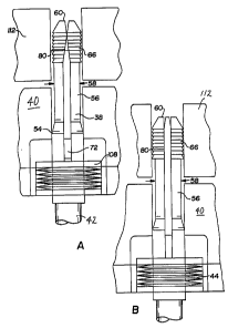
Referring now to FIG. 1, a first embodiment of a workholder 10 is
shown and described. Workholder 10 generally comprises clamping device 12
mounted to support platform 14. Support platform 14 has an upper surface 18
and a lower surface 20 which is adjacent to a lower cavity 22. Upper surface
18
is preferably machined to specific tolerances (for reasons which will be
discussed). Clamping device 12 generally includes a cylindrical expandable
arbor 38, elevated support 40, hydraulic cylinder 42, spring element 44, and
wedge 46.
Referring now to FIG. 2, cylindrical expandable arbor 38 of
clamping device 12 is described in greater detail. Cylindrical expandable
arbor
38 has a first portion 48 having an outer diameter 50 extending a
predetermined
length 52 along first portion 48. At a transition point 54, first portion 48
chamfers
inwardly to second portion 56. Second portion 56 has a second diameter 58
which extends upwardly along second portion 56 until reaching tip 60. Slit 62
CA 02324738 2000-10-26
extends upwardly along cylindrical expandable arbor 38 from a first end 64 and
,
terminates at a point distally located from first portion 48, preferably tip
60.'
Around the upper area of second portion 56 is located a series of serrated
edges 66. As shown in FIG. 3, serrated edges 66 generally have sloped upper
area 68 and jagged downward surfaces 70. By this way, serrated edges 66 are
able to draw traction force in a downward direction with respect to
cylindrical
expandable arbor 38.
Referring now to FIG. 4A and FIG. 4B, wedge 46 is described in
greater detail. As is shown, wedge 46 has a pair of wings 72 which extend
outwardly from a central body 74. At the upper portion of central body 74,
central body 74 chamfers at area 76 toward a point 78.
Referring now to FIG. 5, cylindrical expandable arbor 38 is shown
assembled with wedge 46. As shown, wings 72 are positioned proximate end
64 and extend outwardly from both sides of cylindrical expandable arbor 38.
Central body 74 of wedge 46 extends upwardly inside slit 62 until being
proximate narrowed region 80.
Referring now to FIG. 6, elevated support 40 is described in
greater detail. Elevated support 40 has a upper cylindrical region 82 and an
outer rim 84. Both upper cylindrical region 82 and outer rim 84 have a pair of
locating surfaces 86. Passage 88 extends through elevated support 40
downward to a predetermined depth 94. Inner diameter 92 is substantially equal
to outer diameter 50 of cylindrical expandable arbor 38 to provide lateral
support
of cylindrical expandable arbor 38. Elevated support 40 further has a pair of
square slots 96 which are dimensioned to accommodate wings ?2. A lower part
of elevated support 40 is a counterbore 100. Counterbore 100 has a diameter
substantially larger than diameter 92. In FIG. 7, a sectional view of section
7-7
in FIG. 6 is shown. Here, square slots 96 can clearly be seen. Moreover, the
extension of passage 88 to predetermined depth 94 is also readily understood.
Referring again to FIG. 1, the assembly of clamping device 12 will
now be discussed. Cylindrical expandable arbor 38 passes through passage 88
and is operationally engaged to hydraulic cylinder 42. In its unclamped state,
a
-5-
CA 02324738 2000-10-26
part of first portion 48 of cylindrical expandable arbor 38 is flush against a
,
portion of inner diameter 92 of elevated support 40. Counterbore 100, outer'
diameter 102 of support platform 14 and upper face 104 form the bounds of a
cavity 106. Within cavity 106 and positioned on spacer 108 is spring element
44. Preferably, spring element 44 is a plurality of stacked belleville
washers.
Positioned on spring element 44 is spacer 110. Spacer 108 and spacer 110 are
dimensioned such that the bottoms of wings 72 are flush against the upper area
of spacer 110.
Referring now to FIG. 8A, 8B, and 8C, the operation of the present
invention will be described. In FIG. 8A, work piece 112 is shown positioned
around second portion 56 of cylindrical expandable arbor 38. In operation,
hydraulic cylinder 42 draws cylindrical expandable arbor 38 downward, thereby
causing wing 72 to contact spacer 108. As shown in FIG. 8B, this contact
begins compressing spring element 44 which exerts a force opposite to that of
hydraulic cylinder 42, thereby causing wedge 46 to move upward toward tip 60
and expand second portion 56. This expansion drives serrated edges 66 into
work piece 112. This expansion results in clamping of work piece 112.
It is noted that in the clamped position, first portion 48 and
transition point 54 are no longer adjacent to inner diameter 92 of passage 88.
Instead, the smaller diameter in the second portion 56 is proximate inner
diameter 92. Because of this smaller diameter, cylindrical region 82 is no
longer .
providing support to cylindrical expandable arbor 38. This allows cylindrical
expandable arbor 38 to flex and accommodate for any variations in the location
of bores in the work piece 112.
Referring now to FIG. 8C, continued retraction of cylindrical
expandable arbor 38 by hydraulic cylinder 42 draws work piece 112 against
locating surface 86 of elevated support 40. It is noted that the spring
constant of
spring element 44 changes the amount of clamping pressure exerted on the
walls of work piece 112 before work piece 112 is brought against locating
surface 86. As such, if one desires a large amount of clamping force on the
walls of work piece 112, one would use a spring element 44 with a large spring
-6-
CA 02324738 2000-10-26
constant. A large amount of force required to compress spring element 44 ,
would cause a large expansion force of cylindrical expandable arbor 38 before'
the force would equalize and spring element 44 would be compressed. This
large spring force could be any force which ensures that the bore is clamped
before it is drawn against locating surface 86. If sufficient clamping force
is not
obtained before the work piece is drawn against locating surface 86, then the
insufficient force could cause cylindrical expandable arbor 38 to broach the
bore.
If too much force is applied, then the internal bore could be permanently
marked. The proper forces can be obtained without undue experimentation and
depends on the material which the work piece is constructed from.
Referring now to FIG. 9, a second embodiment of the present
invention is shown and described. Here, spacer 108 and 110 and spring
element 44 are replaced by a smaller diameter bore 25 in support platform 14.
When hydraulic cylinder 42 draws cylindrical expandable arbor 38 downward,
wing 72 intersect support platform 14 instead of spacer 108 of the first
embodiment. As such, the support platform 14, itself, provides the required
opposite force on wing 72 for clamping action. Although this embodiment does
not provide the clamping force distribution as the springs in the first
embodiment, it does result in reduced construction costs.
Referring now to FIG. 10, a third embodiment of the present
invention is shown and described. Here, two separate clamping devices 12 are
mounted to support platform 14. Each clamping device 12 operates as
disclosed in the first embodiment above. Each clamping device is positioned to
clamp a different bore on one work piece. Because of the absence of support.
on cylindrical expandable arbor 38 by cylindrical region 82, as discussed in
the
first embodiment, each cylindrical expandable arbor 38 is able to laterally
flex.
As a result, a work piece having inaccurate, rough, bores can be clamped
without the requirement that each bore be an accurate distance away from the
respective bore.
In FIG. 11, a fourth embodiment is shown having two clamping
devices 12 and 122. A locator assembly 16 is mounted to locating surface 86 of
-7-
CA 02324738 2000-10-26
clamping device 122. Locator assembly 16 is attached to locating surface 86 .
and support platform 14 by bolt 32. Here, locator assembly 16 acts to slide
into'
a bore and accurately position a work piece which is being machined. Thus, in
operation, bores contained in a work piece are slid over a respective
cylindrical
expandable arbor 38 of clamping device 12 and 122 as well as locator assembly
16. The locator assembly 16 serves to accurately position the work piece while
the clamping devices 12 and 122 serve to secure the work piece.
In FIG. 12, a fifth embodiment of the present invention is shown
having a clamping device 12 and clamping devices 122 (which have locator
assemblies 16. Unlike the locator in the fourth embodiment, the plurality of
locators 16 in the fifth embodiment restrain the work piece from moving in
both
translational (x and y) as well as rotational about any one locator assembly
16.
Also, clamping devices 122 and 12 are shown positioned in a non-linear
relationship and, preferably, in a triangular configuration. As such, a
maximum
amount of stability from rotational and lateral movement is provided to a work
piece.
The invention being thus described, it will be obvious that the
same may be varied in many ways. Such variations are not to be regarded as a
departure from the spirit and scope of the invention. Such variations or
modifications, as would be obvious to one skilled in the art, are intended to
be
included within the scope of the following claims.
_g_