Language selection

Search

Patent 2324795 Summary

Third-party information liability

Some of the information on this Web page has been provided by external sources. The Government of Canada is not responsible for the accuracy, reliability or currency of the information supplied by external sources. Users wishing to rely upon this information should consult directly with the source of the information. Content provided by external sources is not subject to official languages, privacy and accessibility requirements.

Claims and Abstract availability

Any discrepancies in the text and image of the Claims and Abstract are due to differing posting times. Text of the Claims and Abstract are posted:

  • At the time the application is open to public inspection;
  • At the time of issue of the patent (grant).
(12) Patent: (11) CA 2324795
(54) English Title: INSERTED LASER WELDED BLANKS
(54) French Title: FLANS RAPPORTES SOUDES PAR FAISCEAU LASER
Status: Expired
Bibliographic Data
(51) International Patent Classification (IPC):
  • B23K 26/044 (2014.01)
  • B23K 26/00 (2014.01)
  • B23K 26/24 (2014.01)
(72) Inventors :
  • BLACK, GARY KEITH (Canada)
  • MORRIS, BRIAN (Canada)
  • STAPLES, MICHAEL JAMES (Canada)
(73) Owners :
  • POWERLASERS LTD. (Canada)
(71) Applicants :
  • POWERLASERS LTD. (Canada)
(74) Agent: BLAKE, CASSELS & GRAYDON LLP
(74) Associate agent:
(45) Issued: 2009-02-10
(22) Filed Date: 2000-10-25
(41) Open to Public Inspection: 2002-04-25
Examination requested: 2005-10-25
Availability of licence: N/A
(25) Language of filing: English

Patent Cooperation Treaty (PCT): No

(30) Application Priority Data: None

Abstracts

English Abstract

A method of creating a tailored blank assembly, the assembly comprising a first blank having an aperture and a second blank having an embossment. The first and second blanks being positioned in a face to face relation and the configuration of the embossment being complementary to and nested within the aperture. The first and second blanks are welded together about the embossment to join the first and second blanks.


French Abstract

Méthode de création d'ensemble de flans taillés sur mesure. L'ensemble comprend un premier flan présentant une ouverture et un deuxième flan présentant une saillie. Les premier et deuxième flans sont placés face à face, et la configuration de la saillie épouse l'ouverture et s'emboîte dans celle-ci. Les premier et deuxième flans sont soudés ensemble autour de la saillie.

Claims

Note: Claims are shown in the official language in which they were submitted.


Claims:

1. A method of forming a tailored blank having two constituent parts, the
method comprising the
steps of providing a first constituent part having an aperture; providing a
second constituent part
of substantially uniform cross section having an embossment to fit the
aperture and a
surrounding flange to extend beyond the periphery of said aperture and overlap
the first
constituent part, the embossment being offset from the flange by the thickness
of the first
constituent part; positioning said first and second constituent parts in face
to face relation such
that said embossment of said second constituent part nests within said
aperture with said flange
overlapping said first constituent part; securing the first and second
constituent parts to one
another to form a substantially planar tailored blank by laser welding said
flange to said first
constituent part to form a continuous weld between the flange and said first
constituent part,
wherein nesting said embossment within said aperture results in a flush
surface between said first
constituent part and said embossment.

2. A method according to claim 1 wherein said first constituent part and said
second constituent
part are of different thicknesses.

3. A method according to claim 1 or 2 wherein said laser weld is located in
said flange.

4. A method according to any one of claims 1 to 3 wherein said laser welding
is performed so as
to penetrate only partially said first constituent part.

5. A tailored blank comprising a first constituent part having an aperture; a
second constituent
part of substantially uniform cross section having an embossment to fit the
aperture and a
surrounding flange extending beyond the periphery of said aperture and
overlapping the first
constituent part, the embossment being offset from the flange by the thickness
of the first
constituent part; said first and second constituent parts being placed in face
to face relation with
said second constituent part nesting said embossment within said aperture to
provide a flush
surface between said first constituent part and said embossment; said first
and second constituent
parts being secured to one another to form a substantially planar tailored
blank by a laser weld
extending continuously between said flange and said first constituent part.

4


6. A tailored blank according to claim 5 wherein said first constituent part
and said second
constituent part are of different thicknesses.

7. A tailored blank according to claim 5 or 6 wherein said laser weld is
located in said flange.
8. A tailored blank according to any one of claims 5, 6, or 7 wherein said
laser weld penetrates
only partially said first constituent part.


Description

Note: Descriptions are shown in the official language in which they were submitted.


CA 02324795 2007-12-20
. . *

INSERTED LASER WELDED BLANKS
FIELD OF THE INVENTION
The present invention relates to a method of producing tailored blanks that
are to
undergo further manufacturing processes to produce shaped metal parts.
BACKGROUND OF THE INVENTION
Traditionally, metal blanks are produced and sold in standard gauges and are
used
in subsequent forming operations to produce a 3-dimensional component, for
example as
part of a vehicle body. The gauge selected for a particular application is
based on the
maximum load that will be applied at any point on the blank. For example, a
door panel
has higher loads at the hinge and rail mounting areas and thus requires
relatively thicker
gauge material. Areas away from these areas are thicker than local strength
requirements
dictate, which results in excess material, and therefore excess weight.
Tailor welded blanks attempt to reduce vehicle weight by placing thicker
gauges
of material in areas where higher strength is required. The blanks are
provided by
abutting a pair of different gauge blanks and then welding along their common
edges.
Butt-welding relies on the precision shearing of the edges to be welded. This
process can
be time consuming and can produce a large amount of scrap material. PCT
International
Publication no. WO 98/31485 describes a method for tailor welding blanks.
Additionally, traditional tailor welded blanks have a step at the seam where
the
material thickness increases. This step can hinder material flow during
forming and can
cause problems during the hemming process.
It is desirable to produce a tailor welded blank that obviates and mitigates
the
above disadvantages and further optimizes the use of materials in order to
decrease
overall weight of the finished component.

SUM1vIARY OF THE INVENTION
In accordance with the present invention there is provided a method for
creating a
tailored blank assembly in which thicker material is placed at locations where
there are
higher strength requirements.

1


CA 02324795 2007-12-20

According to one aspect of the invention, there is provided a method of
joining
two blanks comprising the steps of: providing a first blank of sheet material
having a first
thickness and an aperture formed in said sheet material; providing a second
blank of sheet
material having an embossment to offset a portion of one face of said
material. The
embossment having a configuration that is a complementary fit to the aperture;
positioning the first blank in a face to face relation with the second blank
nesting the
embossment within the aperture; and laser welding about the embossment to join
the first
blank to the second blank.
Preferably, the first and second blanks are of different thickness.
BRIEF DESCRIPTION OF THE DR.AWINGS
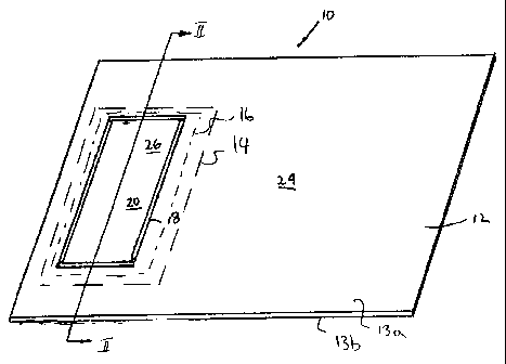
Figure 1 is an isometric view of a tailored blank using the method of the
present
invention;

Figure 2 is a side cross-sectional view of the tailored blank of Figure 1; and
Figure 3 is an isometric view of the tailored blank of Figure 1 shown from the
opposite side.

DETAILED DESCRIPTION OF A PREFERRED EMBODIMENT
A welded tailored blank assembly 10 of the present invention is shown in
Figure
1. The assembly 10 comprises a first blank 12 and a second blank 14. Each
blank 12, 14
is a weldable sheet metal and has oppositely directed surfaces 13 a,b, 15 a,b,
respectively.
The blanks 12, 14 are joined together along a weld seam 16. Each blank 12, 14
is
generally planar, having a rectangular outline. Typically, one blank,
preferably 12, is
thinner than the other, preferably blank 14.
The first blank 12 has an aperture 18 extending between the surfaces 13a, 13b.
Aperture 18 is shown as rectangular, however, it is readily understood that
aperture 18
can be any shape. The aperture 18 is formed in the blank 12 by any known
method, for
example, cutting or punching.
A second blank 14 is provided with an embossment 20 and a peripheral flange 30
as seen in figure 2. The embossment 20 may be formed by any known method.

2


CA 02324795 2007-12-20

Embossment 20 includes a step 28 that preferably has a height equal to the
thickness of the first blank 12 so as to offset a portion of the surface 15a
from the balance
by the thickness of the blank 12. The embossment 20 should be the same shape
as and
slightly smaller than the aperture 18 to provide a complementary fit therein.
Embossment 20 is nested in aperture 18 such that the surface 13b of blank 12
is
juxtaposed in a face to face relation with surface 15a of blank 14. The flange
30 abuts
the adjacent face of the blank 12 and because the step 28 is equal to the
thickness of the
blank 14 ensures that the surface 26 is flush with or substantially co-planar
with the
surface 24 of the first blank 12. This arrangement of providing a flat surface
allows for
improved material flow during subsequent forming processes.
The size and location of aperture 18 and embossment 20 is determined where
extra strength is required for the assembly 10. Preferably aperture 18 and
embossment 20
are spaced inwardly from the outer edge of the blanks 12, 14 respectively.
As, can be seen in Figure 2, a laser beam is directed along a path outside of
the
perimeter of the embossment 20 and the aperture 18 to produce a weld 16 and
join the
two blanks 12, 14 together. The second blank 14 must be of sufficient size to
allow for a
weld to join the blanks together. The weld 16 is performed from the face 15b
of the
second blank 14 so as to penetrate only partially the blank 12. This avoids
distortion or
marking of the surface 13a. The weld 16 is typically a lap weld and the
overlap between
the flange 30 and blank 12 ensures that the weld location does not need to be
accurate. It
is also possible to place a fillet weld between the edge of blank 12 and the
embossment
2o ; however, this requires a higher precision operation.
Although the invention has been described with reference to certain specific
embodiments, various modifications thereof will be apparent to those skilled
in the art
without departing from the scope of the invention as outlined in the claims
appended
hereto.

3

Representative Drawing
A single figure which represents the drawing illustrating the invention.
Administrative Status

For a clearer understanding of the status of the application/patent presented on this page, the site Disclaimer , as well as the definitions for Patent , Administrative Status , Maintenance Fee  and Payment History  should be consulted.

Administrative Status

Title Date
Forecasted Issue Date 2009-02-10
(22) Filed 2000-10-25
(41) Open to Public Inspection 2002-04-25
Examination Requested 2005-10-25
(45) Issued 2009-02-10
Expired 2020-10-26

Abandonment History

There is no abandonment history.

Payment History

Fee Type Anniversary Year Due Date Amount Paid Paid Date
Application Fee $300.00 2000-10-25
Registration of a document - section 124 $100.00 2001-07-27
Maintenance Fee - Application - New Act 2 2002-10-25 $100.00 2002-10-17
Maintenance Fee - Application - New Act 3 2003-10-27 $100.00 2003-10-27
Maintenance Fee - Application - New Act 4 2004-10-25 $100.00 2004-10-12
Maintenance Fee - Application - New Act 5 2005-10-25 $200.00 2005-08-23
Request for Examination $800.00 2005-10-25
Maintenance Fee - Application - New Act 6 2006-10-25 $200.00 2006-09-06
Maintenance Fee - Application - New Act 7 2007-10-25 $200.00 2007-07-31
Maintenance Fee - Application - New Act 8 2008-10-27 $200.00 2008-10-09
Final Fee $300.00 2008-11-26
Maintenance Fee - Patent - New Act 9 2009-10-26 $200.00 2009-09-15
Maintenance Fee - Patent - New Act 10 2010-10-25 $250.00 2010-09-29
Maintenance Fee - Patent - New Act 11 2011-10-25 $250.00 2011-10-04
Maintenance Fee - Patent - New Act 12 2012-10-25 $250.00 2012-10-03
Maintenance Fee - Patent - New Act 13 2013-10-25 $250.00 2013-09-23
Maintenance Fee - Patent - New Act 14 2014-10-27 $250.00 2014-10-10
Maintenance Fee - Patent - New Act 15 2015-10-26 $450.00 2015-10-15
Maintenance Fee - Patent - New Act 16 2016-10-25 $450.00 2016-07-25
Maintenance Fee - Patent - New Act 17 2017-10-25 $450.00 2017-07-20
Maintenance Fee - Patent - New Act 18 2018-10-25 $450.00 2018-10-17
Maintenance Fee - Patent - New Act 19 2019-10-25 $450.00 2019-09-12
Owners on Record

Note: Records showing the ownership history in alphabetical order.

Current Owners on Record
POWERLASERS LTD.
Past Owners on Record
BLACK, GARY KEITH
MORRIS, BRIAN
STAPLES, MICHAEL JAMES
Past Owners that do not appear in the "Owners on Record" listing will appear in other documentation within the application.
Documents

To view selected files, please enter reCAPTCHA code :


To view images, click a link in the Document Description column. To download the documents, select one or more checkboxes in the first column and then click the "Download Selected in PDF format (Zip Archive)" or the "Download Selected as Single PDF" button.

List of published and non-published patent-specific documents on the CPD .

If you have any difficulty accessing content, you can call the Client Service Centre at 1-866-997-1936 or send them an e-mail at CIPO Client Service Centre.


Document
Description 
Date
(yyyy-mm-dd) 
Number of pages   Size of Image (KB) 
Drawings 2000-10-25 3 44
Representative Drawing 2002-04-03 1 7
Abstract 2003-10-29 1 13
Abstract 2002-01-29 1 13
Claims 2000-10-25 1 39
Description 2000-10-25 3 149
Cover Page 2002-04-05 1 24
Claims 2007-12-20 2 60
Description 2007-12-20 3 141
Drawings 2007-12-20 4 61
Claims 2008-03-07 2 62
Cover Page 2009-01-21 2 36
Representative Drawing 2009-01-22 1 8
Correspondence 2000-12-08 1 2
Assignment 2000-10-25 2 89
Assignment 2001-07-27 3 117
Assignment 2002-01-29 1 26
Correspondence 2002-01-29 2 40
Fees 2003-10-27 1 25
Fees 2004-10-12 1 30
Correspondence 2004-10-12 2 46
Correspondence 2004-11-01 1 17
Fees 2005-08-23 1 25
Maintenance Fee Payment 2017-07-20 1 33
Prosecution-Amendment 2005-10-25 1 31
Fees 2006-03-14 1 26
Prosecution-Amendment 2006-04-04 1 32
Fees 2006-09-06 1 27
Prosecution-Amendment 2007-06-22 5 208
Fees 2007-07-31 1 26
Prosecution-Amendment 2007-12-20 19 581
Prosecution-Amendment 2008-03-07 4 104
Correspondence 2008-11-26 1 38
Fees 2008-10-09 1 25
Fees 2009-09-15 1 201
Fees 2011-10-04 1 163
Fees 2012-10-03 1 163
Fees 2015-10-15 1 33