Note: Descriptions are shown in the official language in which they were submitted.
CA 02325006 2000-OS-26
WO 99/28038 PCT/GB98/03586 _
-1-
.RI PI I()N
DEVICE AND APPARATUS FOR CONDUCTING AN ASSAY
The present invention relates to an apparatus, instrument and device for
conducting an assay. More particularly, it relates to a device suitable for
use in
assaying analytes, for example glycated proteins in biological samples such
as,
for example, blood.
The percentage of total haemoglobin (Hb) that is glycated is widely
regarded as an important tool in diabetes management, because it provides an
indirect measure of the mean blood glucose concentration over the previous 2-3
months. One of the three main methods available for assaying glycated Hb
relies on boronate affinity. In this method glycohaemoglobin can be separated
from non glycohaemogiobin thmugh condensation of solid-phase
dihydroxyboronate with the cis-diols present on the sugar moieties of
glycohaemoglobin. This method is specific for all glycohaemoglobins which is
an advantage over other methods, which rely on separation based on difference
in net charge.
However, although the boronate method has certain advantages, it
remains an assay which requires laboratory facilities and quite complicated
equipment. In particular, the need to determine the percentage of glycated Hb
present means that two assay results need to obtained and a comparison made.
It is the case that rapid diagnostic assays have been developed, and continue
to
CA 02325006 2000-OS-26
WO 99/28038 PCT/GB98103586 -
-2-
be developed, which make use of "simple" easy to use diagrmstic devices, which
can be used either by a subject in their own home, or by a subject's own
doctor
in the surgery. One example of such a test device is that marketed by Cortecs
Diagnostics as HELISAL~ONE-STEP, which is for the detection of H. pylori
infection. The principle of this device is, however, generally applicable to a
range of assays. The device consists of two parts, a sample collector and a
second part containing an assay strip. The collector is used to collect a
sample
(of blood in the case of HELISALmONE-STEP) aril the collector is then inserted
into the second part, with which it interconnects, to release the sample to an
assay strip. The sample travels along the strip through various "zones" which
contain various reagents, including a coloured label (blue latex particles).
If
antibodies to H. pylori are present then the label concentrates in a detection
zone. The specifics of this particular assay are not important, however. The
essential features which are common to this type of assay and which allow its
use in the home or doctor's surgery are the ease of sample collection and
handling as well as the simplicity in initiating the reaction and the speed
with
which the result is obtained. Such one-step devices can be utilised in the
measurement of glycated Hb but only if the assay method can incorporate the
necessary sample treatment to allow comparison of total protein with glycated
protein.
To that end, therefore, we have in a first aspect of the invention devised
an apparatus which allows rapid, easy sample treatment combined with
CA 02325006 2000-OS-26
WO 99/28038
-3-
compatibility with a one-step device such as that exemplified by
HELISAL~'ONE-STEP.
PCT/G898/03586
According to a first aspect the present invention there is provided an
apparatus, for use in an assay in which a sample is presented to an
instrument,
comprising a first inlet, a second inlet, aml an inlet port, said inlet port
being
moveable relative to each of said first and second inlets such that the port
can be
brought into liquid communication with each inlet in turn as required, wherein
said inlet port accommodates a filter means or a binder retaining means.
In one embodi~nt the apparatus is adapted to be used in an assay system
where some form of particulate is added to a sample which may contain a
detectable analyte, where the particulate is capable of binding the analyte.
Thus
when the sample plus particulate is added to the inlet port, the particulate,
with
bound analyte, is retained by the filter. The filter can of course be
constructed
of any suitable material. Suitably, it will be made of material which is inert
in
terms of the analyte etc. Also the "mesh" of the filter must be such that it
is
capable of retaining particulates as used in the separation step. The inlet
port
can then be moved into alignment with the second inlet means a~ one or more
reagents capable of interfering with the binding of the analyte to the
particulate
can be added to the inlet port. The analyte (if present) will then pass
through
the filter in solution, leaving the particulates behind.
Thus, taking the example of glycated Hb, a sample of blood is treated to
CA 02325006 2000-OS-26
wo 99nso3s
-4-
PCT/G B98/03586
lyse the blood cells and is then admixed with particulates, eg agarose or
cellulose, to which is bound phenyl boronate. The treated sample is then
introduced into the apparatus via the inlet port, which will have been moved
into
liquid communication with the first inlet. The liquid part of the sample,
which
contains non-glycated Hb, will pass through into the body of the apparatus,
while the particulates, to which will be bound any glycated Hb, will be
retained
by the filter means associated with the inlet port. The inlet port can then be
moved into liquid communication with the second inlet and the particulates can
be washed with one or more suitable reagents to cause release of the bound
glycated Hb from the particulates.
In an alternative approach, the inlet port can incorporate means capable
of binding the analyte. For example, it could incorporate particulates such as
those described above. Thus, in one embodiment the invention provides
apparatus for use in a diagnostic assay, comprising a first inlet, a second
inlet
and an inlet port, said inlet port being moveable relative to each of said
first and
second inlets such that the port can be brought into liquid communication with
each inlet in turn as required, wherein said inlet port incorporates binding
means, capable of binding an analyte which may be present in a biological
sample. Such an apparatus would of course also incorporate some means of
retaining the binding means in the inlet port.
In preferred embodi~nts of both the above-described aspects of the
invention, the apparatus will also incorporate a third inlet, and the inlet
port will
CA 02325006 2000-OS-26
wo 99n8o38
PCT/G B98/03586
-5-
be capable of being moved between the three inlets as required. The third
inlet
will ideally be placed in an intermediate position between the first a~ second
inlets. The provision of this third inlet will allow for an intermediate
washing
step to be carried out prior to treating the binding means to release the
analyte.
In one embodiment the apparatus will be generally circular and the inlet port
will forth part of a rotatable top portion of the apparatus.
In another embodiment the inlet port will be stationary and the first and
second inlets will rotate into communication with the inlet port
As described above the apparatus of the present invention allows a
relatively unskilled operative to treat samples, eg blood samples, for
assaying in
systems such as that used for t~asuring glycated haemoglobin.
In a preferred embodiment of the above described aspects of the
invention the apparatus is designed to be used in conjunction with one-step
assay
devices such as those described in WO 97/18036. Thus, the apparatus of the
present invention can be adapted to allow insertion of one or more sample
collectors as described in WO 97/18036. In practice the one or more sample
collectors will be inserted such that they are in liquid communication with
the
first and/or the second inlets. Thus, in use, a first sample collector can be
inserted such that it is in liquid communication with the first inlet. In the
case of
the first aspect described above, the inlet port will also initially be in
liquid
CA 02325006 2000-OS-26
WO 99/28038
PCT/GB98/03586
-6-
communication with the first inlet and the sample plus particulate is added to
the
inlet port which will retain the particulate, and any bound analyte, allowing
the
rest of the sample to pass through for collection by the first sample
collector.
This sample collector can then be removed and inserted into a test
instrument as described in WO 97/ 18036. The inlet port can then be moved to
the intermediate inlet (if present) and wash buffer can be added, flowing
through
and into a sink incorporated in the apparatus. The inlet port can them be
moved
into liquid communication with the seco~ inlet and one or more reagents can be
added to dissociate the analyte from the particulates. A second sample
collector
can then collect the analyte solution for removal and insertion into a second
one-
step device.
Thus, in the case of assays for glycated haemoglobin, the two results
obtained can be used to calculate a percentage value for glycated haemoglobin.
Conveniently, this can be done using a device such as Cortecs' INSTAQUANT
reader which has been designed for use with one-step assay devices.
Suitably, the apparatus of the invention will be constructed of a liquid
impervious material such as plastic.
In a more preferred embodiment, the apparatus of the invention is
adapted such that the respective samples passing through the first and second
inlets are collected in optical chambers disposed below said first and second
inlets or said first and second inlets are/or include optical chambers. Thus,
in
one embodiment the invention provides an apparatus for use in a diagnostic
CA 02325006 2000-OS-26
WO 99/28038 PCT/GB98/03586
assay comprising a first inlet, a second inlet and an inlet port, said inlet
port
being movable relative to each of said first and second inlets such that the
port
can be brought into liquid communication with each inlet in turn as required,
wherein said first and second inlets are in liquid communication with
associated
optical chambers.
The apparatus is connectable to an instrument which incorporates means
for the spectrophotometric measurement of said samples in the optical
chambers.
According to a second aspect of the invention there is provided an
instrument, for reading a sample presented in an apparatus, comprising a
microprocessor operable via a key pad, one or more light emitters and one or
more light detectors, a display and driver , an analogue to digital converter,
and
means for connecting the instrument to a power source.
Preferably each optical chamber houses a micro-cuvette and the
instrument comprises means for measuring the absorbance of the contents of
each micro-cuvette. Thus, the instrument comprises a LED light source to
generate electromagnetic radiation at one side of the sample and an associated
photodiode (PD) for measuring the intensity of transmitted light generated
across
the sample i.e. the instrument measures absorbency. Preferably, the instrument
comprises one or more LED/PD pairs. In one embodiment one or more
LED/PD pairs are arranged such that when the instrument is connected to the
apparatus one or more LED/PD pairs are disposed across each optical chamber.
In another embodiment the apparatus and instrument are connected such
CA 02325006 2000-OS-26
WO 99/28038
PCT/GB98/03586 w
_g_
that one or more LED/PD pairs are positioned such that a reading can be taken
of a sample in the first optical chamber and then the same one or more LED/PD
pairs can be moved to read the sample in the second optical chamber.
Alternatively the optical chambers can be moved relative to the one or more
LED/PD pairs.
Producing an instrument with means for the spectrophoto~tric
measurement of said samples proved problematic, since it was necessary to
overcome two conflicting problems, namely that:
1. In normal sleep mode, the current drain was only in the order of ~c amps,
and as a consequence was insufficient to prevent a passivation layer from
building up within the electric cell/battery used to drive the instrument, so
significant voltage drops occurred when the instrument had not been used for
some time; and
2. when running a test, the intermittent loading from the LED's and
analogue circuitry was not sufficient to dispose the passivation layer.
In order to overcome these problems it was necessary to:
1. select a lithium thionyl chloride battery;
2. condition it,
(Conditioning can be achieved by for example applying a IK 9 load for
24 hours. The skilled man will, however, appreciate that higher loads for
shorter period are effective); and
3. regularly switch in a load for a short period of time.
CA 02325006 2000-OS-26
WO 99/28038
PCT/GB98/03586
_g_
In one embodiment a 3.6V lithium thionyl chloride battery is conditioned
by applying a 3.3K !~ load for 7 to 8 hours before soldering the battery onto
the
main PCB.. This assures that the passivation state of the battery is
consistent.
The processor is controlled to wake every second by switching in a 1K n load
for 3.5 mS.
One embodiment of the invention provides an instrument comprising a
microprocessor operable via a key pad, one or more light emitting diodes
(LED's) and one or more associated photodiodes, a display and driver, an
analogue to digital converter, a lithium thionyl chloride battery and a
battery
conditioning circuit.
The battery is conditioned prior to its i~orporation, and soldered, onto a
printed circuit board. Conditioning reduces internal resistance in the battery
which would result in inconsistent voltages a~ readings with unacceptable
variation.
Circuitry and software is provided to maintain the battery conditioning
by repeated discharge of the battery.
Also circuitry and software control systems that energise the LED's in a
timed sequence, to permit voltage recovery to stable levels before circuit
noise
readings are taken and the next reading cycle commencxd are provided.
According to a third aspect of the invention there is provided a device
comprising an apparatus atxi an instrument of the invention.
In a particularly favoured embodiment the apparatus of the invention
CA 02325006 2000-OS-26
WO 99/28038
-10-
comprises three main components:
PCT/G B98/03586
a base portion; a top portion and a funnel portion which serves as the inlet
port.
The top portion is connected to the base portion to form a carousel and
the funnel portion fits within the top portion such that it can in turn
communicate with optical chambers present in the base portion.
The funnel portion has a stem which extends from its centre and serves
to connect the apparatus to the instrument. The inlet port funnels the sample
and
reagents in turn into the respective inlets of the base portion and has an
outlet
displaced from the centre of the funnel. The outlet is designed to either
accommodate a filter means or retain a binding means. Preferably a frit sits
within the outlet supported by, for example, a narrowing of the outlet or a
flange. The funnel portion further comprises an annular ring which serves as a
guide member about which the carousel comprising the top portion and base
portion rotate. The annular ring has a cut away or recessed portion thereby
allowing tubes, housed vertically in the carousel, to be presented to the user
at
the appropriate times during the assay procedure. Housing the tubes vertically
reduces the size of the apparatus and reduces packaging costs. An inclined
ramp
disposed on the floor of the instrument upon which the apparatus sits cause
respective tubes to be lifted through openings in the top portion as the
carousel
is rotated on the instrument. The annular ring thus also functions to retain
the
tubes until they are ready for presentation thus making sure the assay
reagents
are presented in a correct order.
CA 02325006 2000-OS-26
WO 99/28038
-11-
PCT/GB98/03586 w
The top surface of the top portion, as noted above, comprises a plurality
of apertures through which respective tubes containing the reagents pass.
The top portion also has an indicator means, which denotes the position
for location of the apparatus on the instrument. Preferably, this is in the
form of
a projecting member which assists the operator to turn the apparatus in the
instrument, and more importantly it can be alig~d with markers denoting
operating positions on the instrument.
The base portion comprises a guide member of a guide pair, which in use
co-operate with the other members of the guide pair on the instrument. In a
preferred embodiment the base portion has on its side a guide member, for
example, in the form of a projecting member which enables the apparatus to be
retained and moved in an annular channel in the instrument. The guide member
also importantly functions to maintain the optical chambers of the apparatus
in a
position such that accurate readings can be taken. The base portion comprises
a
first and second inlet in the form of optical chambers which optical chambers
can be rotated with the base portion to be in liquid communication with the
inlet
port. The optical chambers have a geometry so that the LED's in the instrument
can be positioned at the centre of curvature. This has the advantage that all
rays
in the horizontal plane will be perpendicular to the walls of the optical
chamber
and should not be subject to refraction. This relaxes rotational location
tolerances of the apparatus.
Preferably the optical surfaces of the optical chambers will be recessed to
CA 02325006 2000-OS-26
WO 99/28038
PCT/GB98/03586 w
-12-
avoid damage on rotation and prevent a risk of them picking up dirt on
handling.
The third inlet which need not be an optical chamber will preferably
contain a means for drawing the wash liquid through. Such means might
include an absorbent or wicking material such as, for example, filter paper.
Other materials such as, for example, acetate based weaves, felts and the like
could, however, be used.
Preferably the top and base portions are connected in a manner such that
used - reagents are sealed therein. This is most conveniently achieved using a
ring seal between the portions.
Preferably, the base unit is made of a clear material, although depending
on the application of the apparatus a tinted or coloured material, preferably
plastics could be used. Alternatively, an optical filter can be positioned in
front
of the optical chamber and a white light source used. The optical filter is
preferably a wavelength filter.
The apparatus is intended to be disposable.
The apparatus is designed to operate on a ratchet mechanism so that it
can only be rotated in one direction on the instrument.
In a particularly favoured embodiment the instrument is run, not from a
lithium thionyl chloride battery under the control of a battery conditioning
circuit but from an external source, for example, a mains source or car
battery
via a transformer. Consequently, the apparatus is provided with a power
management and monitoring circuit. Preferably the instrument is provided with
CA 02325006 2000-OS-26
WO 99/28038
-13-
PCT/GB98/03586
a communications system such as, for example, an RS 232 thereby providing
means for sending and receiving instructions and down loading data.
The instrument's electronics are housed in a case which is specially
adapted for use with the apparatus of the invention. It comprises a recess
into
which the apparatus of the invention sits. The recess is defined by a floor,
an
innermost side wall (which is the outer wall of a spigot projecting from the
floor) and an outermost side wall. The spigot which projects upwards from the
floor of the recess has a portion which mates with a recess in the stem of the
funnel portion of the apparatus. Thus, the recess is substantially annular.
The
outermost side wall has a channel member running about its circumference.
This chancel is shaped to accept a guide member projecting from the apparatus.
This arrangement enables smooth rotation of the apparatus in the instrument
and
importantly assist in aligning the optical chambers of the apparatus with the
light
emitter/light detector arrangement of the instrument. The light emitter/Gght
detector arrangement preferably comprises a LED/PD arrangement. The LED's
and photodiodes are most preferably arranged such that the reading path of the
instrument lies across part of the annular recess. Thus, the innermost and
outermost side walls are provided with respective windows through which a path
of light from the LED's to the photodiodes can travel. Most preferably the
LED's are housed in the outermost wall and the light passes through the
optical
chamber towards the spigot in which the photodiodes are housed. The LED's
and photodiodes could, however, be arranged the other way around. However,
CA 02325006 2000-OS-26
WO 99/28038
PCT/GB98/03586
-14-
with the former arrangement the convex face of the optical chambers help focus
the light giving more accurate readings.
Another feature of the instnunent design is a connecting channel running
from the top surface of the instrument to the circumferential channel r~mber
so
as to allow the guide member of the apparatus to be inserted in a set
position.
Once the apparatus is rotated it is locked in the instrument until it returns
to the
connecting channel from which it can exit. Also, a ramp is provided on the
floor of the instrument's recess so that when the tubes housed in the
apparatus
contact the ramp as the apparatus is rotated they are lifted presenting them
to the
user.
The various aspects of the invention will now be described by way of
example only, with reference to the following figures in which:
Fig. 1 is a perspective view of an embodiment of the first aspect of the
present invention.
Fig. 2 is a block diagram showing the electronics of an instrument of the
4th aspect of the present invention.
Fig. 3 is an embodiment of a device of the present invention.
Fig. 4a is a schematic showing how the device of Fig. 3 is used in an
assay;
Fig. 4b is a flow chart showing a protocol for the use of the device
shown in Fig. 3.
Fig. 5 is a perspective view of a preferred embodiment of an apparatus of
CA 02325006 2000-OS-26
wo 99nso3s
-15-
the invention;
Fig. 6 is a partially sectioned view of the Fig. 5 apparatus;
PCT/G B98/03586
Fig. 7 is a perspective view of the base portion of the apparatus of Fig. 5
and 6.
Fig. 8 is a perspective view of a preferred embodiment of an instrument
of the invention for use with the apparatus illustrated in Figs. 5 and 6; and
Fig. 9 is a perspective view of a preferred device comprising the
apparatus as illustrated in Figs. S and 6 and the instrument as illustrated in
Fig.
8.
Referring to Fig. 1, the apparatus 1 comprises a base section 2 and a
rotatable top portion 6. The rotatable top portion 6 itself comprises a handle
section 8 and an inlet port 9, the inlet port incorporating a filter means 7.
The
base section 2 has three inlets 3, 4 and 5 which are associated with three "O"
rings 11. A foam pad "sink" 10 is inserted in the middle inlet 4 to collect
washing buffer. In this embodiment similar foam pad "sinks" 12 and 13 are
associated with the other inlets 3 and 5. The rotatable top portion 6 is
retained
in place by means of a spring clip 14. Also shown in Fig. 1 are two sample
collectors 15 and 16 which can be inserted into the apparatus 1 by way of
openings 17 and 18 such that they will be in liquid communication with the
inlets 3 a~ 5.
Thus, in operation, the top portion 6 is first moved to a first position
where the inlet port 9 is aligned with the first inlet 3. A first sample
collector
CA 02325006 2000-OS-26
WO 99/28038
PCT/GB98/03586
-16-
15 is inserted in the first opening 17. The sample plus particulate is then
added
to the inlet port 9, where the particulates will be retained by the filter
means 7
allowing the liquid phase to pass through where it is taken up by the sample
collector 15. Any excess liquid will be retained by the "sink" 12.
The top portion 6 is then moved to a second position where the inlet port
is aligned with the intermediate inlet 4 and wash buffer is added to wash the
retained particulates. The wash buffer passes through and is retained by the
"sink" 10.
The top portion 6 is then moved to a third position where the inlet port 9
is aligned with the remaining inlet 5. One or more suitable reagents is then
added to cause the analyte to dissociate from the particulates and pass
through
the filter means 7 to be collected by a second sample collector 16 inserted in
the
apparatus 1 by means of the second opening 18. Each sample collector can be
removed and assays carried out in accordance with the principles described in
WO 97/18036.
According to a fourth aspect of the present invention there is provided
an assay, conducted using an apparatus of the invention wherein a sample is
separated into a first component fraction and a second component fraction and
the assay determines the presence or absence of one or more analytes in said
sample fractions.
As described above, the apparatus of the present invention is particularly
suited to use in assays for glycated proteins such as glycated haemoglobin.
CA 02325006 2000-OS-26
WO 99/28038
-17-
Thus, in one embodiment the present invention provides an assay for
PCT/GB98/03586
determining the percentage of one or more glycated proteins present in a blood
sample, which comprises the step of using an apparatus as described herein to
separate a blood sample into a first component comprising one or more non-
glycated proteins and a second component comprising one or more glycated
proteins.
Preferably, the assay further includes one or more of the following steps:
(i) obtaining a blood sample from a subject:
(ii) treating the blood sample obtained in (i) to lyse the blood cells; and
(iii) providing to the sample obtained in (ii) a means for binding glycated
proteins, for example a solid phase to which is bound one or more reagents
capable of binding glycated proteins.
Examples of glycated proteins whfch can be assayed using this method
include glycated haemoglobin, glycated human serum albumin and glycated apo
lipoprotein B. These proteins will be bound by the boronate ligand and so an
assay can be perfor~ci in which all three glycated proteins will be bound to a
particulate. The component containing all three glycated proteins can then be
collected and individual assays can be run to determine the relative amounts
of
each gylcated component. Alternatively, a single one-step device could be used
which had three individual capture zones bearing a reagent specific for each
of
the three glycated proteins. The relative amounts could then be determined
using a device such as the INSTAQUANT reader.
CA 02325006 2000-OS-26
WO 99/28038
-18-
PCT/GB98/03586 w
An apparatus of the present invention can be included in a kit for use in
an assay for one or more glycated proteins. Thus, in a further aspect the
present
invention provides such a kit comprising an apparatus of the invention and
optionally one or more sample collectors or one step assay devices or
reagents.
Examples of suitable one-step assay devices include those described in WO
97/18036, although the skilled person will appreciate that any device designed
to
allow an assay to be carried by simple addition of a sample to an assay strip
can
be used.
Another major advantage of the apparatus of the present invention results
from the ability to combine a "chemical" or biological capture or separation
step, such as the use of the boronate ligand, with an immunoassay or a hand
held
spectrophotometric means.
According to a fifth aspect of the present invention there is provided a kit
comprising an apparatus according to the invention and optionally one or more
sample collectors or one step assay devices or reagents and/or a capillary
tube
and/or an inoculating loop.
According to a sixth aspect of the present invention there is provided a
point of care method for the detection of an analyte in a sample which
comprises:
(i) separation of the analyte from the sample by the use of chemical or
biological
means; and
(ii) detection/quantifying the analyte by means of an immunoassay or
CA 02325006 2000-OS-26
wo 99n8o3s
-19-
spectrophotometric means.
PCT/GB98/03586
As used herein "chemical" means the use of one or more reagents whose
interaction with the analyte is primarily chemical and not biological. For
exaaaple, as described herein, a boronate based separation step can be used to
separate glycated proteins from non-glycated proteins in a sample. Preferably,
step (i) is achieved using apparatus according to the present invention and
step
(ii) is achieved by means of a one-step assay device.
In a preferred embodiment the apparatus of Fig. 1 is modified to include
optical chambers thereby allowing the samples collected to be read
spectophotometrically.
Preferably the discrete optical chambers house micro cuvettes. By
measuring the contents absorbance at a given wave length more accurate
readings, than can be obtained using reflected light, can be obtained. Thus,
preferably the apparatus is adapted to be connected to an instrument with
means
for measuring the absorbence of the liquid collected in the optical chambers.
Figure 2 is a block diagram illustrating the essential components of one such
instrument.
Thus, the instrument comprises a body housing a micro processor
powered by a lithium thionyl chloride battery under the control of a battery
conditioning circuit. Instructions can be transmitted to the micm processor
via a
key pad and information/instructions presented via a liquid crystal display
powered by a LCD driver. The micm processor controls one or more LED's
CA 02325006 2000-OS-26
WO 99/28038
PCT/C B98/03586
-20-
which pass light of a given wave length (420 - 430 nm in the case of an
instnunent for reading glycated haemoglobin) across the optical chambers such
that absorbed light is measured by photodiodes. The readings are communicated
to the liquid crystal display via an analogue digital converter. A micro
switch
determines that the device (apparatus and instrument) is activated by the
correct
connection of the apparatus to the instrument. A LED/phototransistor pair is
provided to determine when the apparatus has been disconnected from the
instrument.
Electronics of the type illustrated in Fig. 2 and controlling software are
incorporated as an integral part of the instrument. The device resulting from
the
connection of the apparatus and instrument is illustrated with reference to
Fig.
3. Thus, the device 20 comprises an apparatus 22 similar to the apparatus 1 of
Fig. 1 and an instrument 24 which houses the electronics.
Apparatus 22 differs from the apparahis of Fig. 1 in that the inlets (which
correspond to inlets 3, 4 and 5 of Fig. 1) communicate with optical chambers
in
the base 2 of the apparatus. The apparatus and instrument are connected to one
another via respective mating members such that a or respective
LED/photodiode pairs present in the instrument are situated on either side of
the
optical chambers or can be presented in turn to said respective optical
chambers
so enabling absorbance readings to be taken and communicated to the display 26
provided in instru~nt 24. A key pad 28 is also provided in instrument 24.
The top 6 and base 2 of apparatus 22 are designed to include a chamber 30 for
CA 02325006 2000-OS-26
wo 99nso3s
PCT/GB98/03586
-21-
housing one or more components of a ldt, for example reagents such as a wash
solution and/or buffer and/or elution buffer and/or a capillary tube. The
chamber 30 is shown in its open position in figure 3.
Referring to Fig. 4 a protocol for operation of the device is as follows:
(i) A finger-prick blood sample is collected into a capillary tube and placed
into the sample buffer tube which contains a buffer and an amino phenyl
boronate (aPBA) agarose affinity matrix. The tube is capped and inverted
several times, which washes the blood out of the tube and into the buffer
where
the red blood cells are lysed thus liberating the haemoglobin.
(ii) The tube is left for approximately 60 - 90 seconds, with occasional
inversion, during which the glycated haemoglobin present in the sample binds
to
the aPBA affinity matrix.
(iii) During this time, the apparatus 22 which is designed to be disposable,
is
coupled to the instrument 24. The location of the apparatus to the instrument
activates the on switch.
(iv) After about 60 - 90 seconds incubation, the contents of the sample buffer
tube are mixod by repeated inversion and then the entire contents are poured
into
the inlet port which is located in position 1.
(v) The liquid contents of the tube drain through a frit or other filter means
located at the bottom of the first inlet a~ collect in an optical chamber in
the
base of the apparatus 22. The aPBA affinity matrix, however, is too large to
pass through the frit and therefore collects in the column at the bottom of
the
CA 02325006 2000-OS-26
WO 99/28038 PCT/GB98/03586
-22-
first inlet.
(vi) The liquid contents collected in the first optical chamber contain the
non-
glycated haemoglobin present in the original sample, the aPBA affinity matrix
collected in the bottom of the inlet port 9 contains the glycated haemoglobin
present in the original sample.
(vii) On completion of this first step, the insaument directs the user to
progress to stage 2, which is accomplished by turning the top part of the
apparatus 22 through 90° and stopping at position 2. Again under the
direction
from the instrument 24 a specific volume of wash buffer is added to the inlet
2
via inlet port 9 and allowed to drain through. This step is to remove any non-
specifically bound non-glycated haemoglobin from the aPBA affinity matrix that
may be present from std 1.
(viii) The instrument 24 then directs the user to progress to stage 3 and add
the
contents of the elution buffer tube to the inlet 3 via inlet port 9 which is
allowed
to drain through the frit and collects into a second optical chamber in the
base of
the apparatus 22. The elution buffer removes the glycated haemoglobin from
the aPBA affinity matrix.
(ix) The instrument 24 then spectophotometrically measures the absorbance
(at 430nm) of both the non-glycated and the glycated haemoglobin fractions
present in the two optical chambers. Using an algorithm built into the
instruments software, the °6 glycated Haemoglobin present in the
original whole
blood sample is calculated and displayed on the display 26.
CA 02325006 2000-OS-26
WO 99/28038 PCT/GB98/03586
-23-
(x) The apparatus 22 is disconnected from the instrument 24 and is discarded
as biohazardous waste. The instrument is then ready to perform the next test.
More particularly the instrument is controlled to operate in accordance
with the protocol outlined with reference to the flow diagram shown in Fig,
4b.
The spectrophoto~ric measurement of both glycated and non glycated
haemoglobin fraction occurs at the interface of the optical chambers of the
apparatus with the instrument 24 of the device.
The most preferred apparatus and instrument are illustrated with
reference to figures 5, 6 and 8 and together they form a device as illustrated
in
Fig. 8
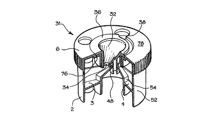
Referring to Figs. 5 and 6 the apparatus 31 comprises a base section 2 of
clear plastics (shown in detail in Fig. 7), a top portion 6 and a funnel
portion 32.
The funnel portion 32 is made of a hydrophobic plastics and has a relatively
large aperture to simplify emptying of reagents therein. It has an outlet 34
which directs the liquid into the optical chambers 3 and 5 when the apparatus
is
rotated in an instruanent. The outlet 34 includes a frit (not shown) which
frit
serves to retain particles such as, for example, an amino phenyl boronate
agarose amity matrix. The funnel 32 which serves as an inlet port has an
annular rim 36 with a recessed portion 38. The rim 36 partially overlies
apertures 40, 42 aad 44 formed in the top portion 6 of the apparatus such that
tubes vertically disposed in the apparatus cannot pass through the respective
apertures until the apertures are aligned with the recessed portion 38 of the
CA 02325006 2000-OS-26
' , ' ; ,
-24-
annular rim. Projecting from the underside of the funnel is a stem 48 with a
female mating member via which the apparatus 31 is connected to the instrument
24 which has a male member 50 adapted to engage it. The male ember 50
holds the funnel in a faced position relative to the instrument 24 such that
the
base portion 2 and top portion 6 of the apparatus 31 which together form a
carousel rotate around the funnel, the annular rim 36 of the funnel serving as
a
guide means.
The base portion 2 of the apparatus is made of a clear plastics, is
generally annular in shape a~ is divided into a plurality of compartments. As
can be seen from Fig. 7 there are two optical chambers 3 and 5, a third
chamber
4, for receiving waste from a wash step, which third chamber is disposed
between optical chambers 3 and 5, and three additional chambers 40', 42' and
4.4' each housing a reagent tube. These chambers 40' , 42' and 44' , which are
disposed below apertures 40, 42 and 44 in the top portion 6 of the apparatus
31,
are arranged so that the reagent tubes are presented to the user when the
carousel is in the position corresponding to positions N, VI and VII per Fig.
4a
or position 1, 2 and 3 as per Fig. 4b. The optical chambers have a curved
outer
wall 52 and a curved inner wall 54 of optical quality, which help focus light
from the LED's of the instrument 24 through the sample in the chamber to
photodiodes at the other side thereof.
Each optical chamber 3, 5 can be brought into liquid communication with
the outlet 34 of the funnel inlet port 9. Alternatively, the optical chambers
can
AMENDED SH~ET
CA 02325006 2000-OS-26
WO 99/28038 PCT/GB98/03586
-25-
be recessed. Extending outwardly from the outermost wall 56 of the base
portion 2 is a guide member 58 which sits within a circumferential channel
member 60 formed on the outermost wall 62 of the annular recess 64 of the
instrument 24. A communicating channel 66 which extends from the channel
member 60 in outermost wall 62 to the top face 68 of the instnunent 24 allows
the guide member 58 to be inserted into the channel member 60 when the
apparatus 31 is connected to the instrument 24.
A projecting member or tab 70 on the knurled edge 72 of the top portion
6 acts as an indicator means, denoting the position for locating the apparatus
on
the instrument and serves to assist in the turning of the apparatus.
The base portion 2 is connected to the top portion and the funnel portion
sits in a channel 7( formed by a step on the top surface 78 of the top portion
6.
The instrument illustrated in Fig. 8 has been designed for use with an
apparatus as herein before described. In essence it is very similar to the
instrument described with reference to figures 2, 3 and 4b. The instrument
illustrated with reference to Fig. 8 does, however, differ from that described
with reference to Fig 2 in one major way and has a number of novel and
advantageously beneficial additional features. Thus, in contrast to the
instrument described with reference to Fig. 2 the lithium thionyl chloride
battery
and battery conditioning circuit is replaced with a power management and
monitoring circuit so that the instrument can be connected to, for example, an
external do supply or a car battery. Additionally, the instnmrent is provided
CA 02325006 2000-OS-26
WO 99/28038 PCT/GB98/03586
-26-
with a communication system such as, for example, a RS232 thereby providing
means for sending and receiving instructions and down loading data.
Significantly, the pans for receiving the apparatus is an annular recess
64 in the instrument which is defined by a floor, an outermost sidewall 62 and
an in~rmost sidewall 80.
The floor of the annular recess comprises a ramp 82 on a part thereof.
Within the outermost sidewall 62 of the annular recess is a channel member 60
and extending therefrom to the top surface 68 a connecting channel 66.
In use the apparatus is inserted into the annular recess 60 by aligning
guide member 58 of the apparatus with connecting channel 66 so that the
apparatus is connected to male mating member 50 via its female mating member
48. The guide member 58 can thus enter channel member 60 such that it can be
rotated. On rotation a first tube is directed up the ramp 82 and out of its
aperture 44 since the recessed portion 38 of the annular ring 36 is aligned
with
the aperture. In this position the outlet 34 is in liquid communication with
the
first optical chamber 3 and the first step of the assay described with
reference to
Figs 4a and 4b can be conducted. By turning the apparatus through a furrber
90° a wash solution is presented through aperture 42 for use and then
on turning
the apparatus though a further 90 ° tube 40, the eluting solution, is
presented. In
this manor the appropriate reagents are presented for each step of the assay
process.
The apparatus and instrument of the invention can be adapted for use in a
CA 02325006 2000-OS-26
WO 99/28038 PCT/GB98/03586
-27-
number of assays.
In particular the instrument can be modified to read at wavelengths other
than the 400 to 500 nm, more particularly 410 to 460 nm, range of the bhie
LED employed for measuring glycated haemoglobin. Thus, for example
coloured light, red, green, yellow etc. LED's or white light and the use of
optical filters more preferably wavelength filters could be employed.
Also the apparatus could be modified to make single measurement rather
than take several readings as exemplified with reference to the assay
described
where a percentage figure is calculated from two readings requiring a
separation
step. Thus, the inlet port and first and second inlets could be replaced by a
carousel type apparatus carrying one or a plurality of optical chambers.
The type of assays might, for example, include:
1. ELISA type assays;
2. Affinity chromatography assays; and
3. Chemical analysis of analytes.
Thus, the wave length spread of the instrument could be adapted to
measure the two most commonly used ELISA substrates ABTS which is
measured at 414 nm and TMB which can be measured at 600nm (blue) or 450
nm (yellow).
Affinity chromatography assays could be used to determine the presence
and/or quantify a number of analytes using spectrophotometric analysis by
selecting the appropriate wavelength.
CA 02325006 2000-OS-26
WO 99/28038 PCT/GB98/03586 w
-28-
Finally, the technology described could be utilised for field testing of
chemical analytes. Thus, for example, water and soil analysis in which
nitrates
or sulphates are calculated or enzyme activity determined are envisaged.
The skilled man will appreciate that the device of the type described
herein and its component apparatus and instrument could be used to measure
levels of various other analytes in a wide range of samples.