Note: Descriptions are shown in the official language in which they were submitted.
CA 02325090 2000-11-03
PERFORMANCE MONITORING FOR OPTICAL TRANSMISSION SYSTEM
BACKGROUND OF THE INVENTION
1. Field of the Invention
The present invention relates to an optical
transmission system and in particular to a performance
monitoring technique for large-capacity and long-distance
transmission requiring error correction processing.
2. Description of the Related Art
With the recent increase in data transmission capacity,
SONET (Synchronous Optical NETwork) or SDH (Synchronous
Digital Hierarchy) has been employed as a basic transmission
scheme for fiber-optic communication systems.
In the SONET/SDH systems, the parity check bytes such
as B1, B2, and B3 in the SONET/SDH frame are used to compute
a transmission error rate based on BIP (Bit Interleaved
Parity) calculation. The frame format of SONET/SDH is shown
in Fig. 6, where Bi byte is used for section (regenerator
section for SDH) bit error rate (BER) monitoring, B2 byte
for line (multiplex section for SDH) BER monitoring, and B3
byte for path BER monitoring.
A parity check byte is computed from all or a
predetermined part of the previous frame for each of section,
CA 02325090 2000-11-03
FQ5-497 2
line and path and is written into a corresponding one of B1,
B2 and B3 bytes. Therefore, the transmission BER for each
of section, line and path can be computed to allow
performance monitoring therefor.
With the vast increase in data transmission capacity,
error-correction techniques compensating for transmission
errors have been employed in the SONET/SDH systems. In this
case, however, the parity check byte cannot be used as it is
for performance monitoring after error correction.
Hereafter, the details will be described, taking as an
example the case of parity check bit for simplicity.
It is assumed that one bit is corrected in an N-bit
frame having a parity check bit included in the overhead
thereof and an actual transmission error rate is Pe.
In the case where the error correction is not performed,
the parity check bit allows one bit error to be detected.
Accordingly, an error rate Pe_bip obtained from the parity
check bit is calculated by the following expression:
Pe_bip = (1/N) ={1 - (1 - Pe)N}.
According to this expression, if the actual
transmission error rate Pe is sufficiently small, then the
calculated error rate Pe_bip is approximately equal to the
actual transmission error rate Pe.
CA 02325090 2000-11-03
FQ5-497 3
Contrarily, in the case where the error correction is
performed, one bit error is corrected and the number of
error bits becomes 0, but k(k>1) bit errors produce (k+1)
bit errors due to miscorrection. Therefore, an error rate
Pefec obtained by performing the error correction is
calculated by the following expression:
N
Pe-feC =(1/N)=X- (k+1)=NCk =(Pe)k(1-Pe)N-k
In this case, the number of error bits counted by the
parity check bit calculation is erroneously incremented by 1
when an even number of error bits occurs. Therefore, an
error rate Pe_fecbip obtained from the parity check bit after
the error correction is calculated by the following
expression:
N/2
Pe_ f,_bip =(1/ N) N C2k '(Pe)zk (1- Pe)N-2k
Accordingly, there occurs an error between the error
rate Pefec obtained after the error correction and the error
rate Pe_fec_bip obtained from the parity check bit after the
error correction. If Pe = 10-' and N = 100, then Pe fec = 1= 48
X 10_12 and Pe_fec_bip - 4. 9 x 10-13 -
CA 02325090 2005-03-15
75372-36
4
As describe above, the conventional performance
monitoring technique based on the existing parity
calculation cannot provide a precise error rate.
SUMMARY OF THE INVENTION
It is an object of the present invention to provide an
optical transmission system and a performance monitoring
method allowing precise error rate evaluations.
According to an aspect of the present invention, in an
optical transmission system for transmitting a signal having
a predetermined frame format from a first element to a
second element, the first element comprises: an error-
correction coder for coding transmission data to produce a
transmission signal subjected to error-correction coding;
and a transmitter for transmitting the transmission signal
to the second element. The second element comprises: a
receiver for receiving a reception signal subjected to the
error-correction coding from the first element; an error-
correction decoder for decoding the reception signal to
produce decoding failure information; and a decoding failure
collector for calculating a number of errors after the error
correction decoding based on the decoding failure
information.
CA 02325090 2005-03-15
75372-36
The decoding failure collector may include an error
counter for determining a number of errors based on an
error-correcting capability of the error correcting code
when a decoding failure occurs. The number of errors,may be
5 determined to be a number greater than the error-correcting
capability.
According to another aspect of the present invention,
the first element comprises: a first parity calculator for
calculating parity information from a frame of transmissipn
data; an overhead controller for inserting the parity
information into an overhead of a next frame of the
transmission data; an error-correction coder for coding the
transmission data with the parity information to produce a
transmission signal subjected to error-correction coding;
and a transmitter for transmitting the transmission signal
to the second element. The second element comprises: a
receiver for receiving a reception signal subjected to the
error-correction coding from the first element; an error-
correction decoder for decoding the reception signal to
produce reception data; a second parity calculator for
calculating parity information from a frame of the reception
data; a parity comparator for comparing the calculated
parity information with parity information extracted from a
next frame of the reception data to determine whether the
calculated parity information perfectly matches the
CA 02325090 2005-03-15
75372-36
6
extracted parity information; and a disparity collector for
calculating a number of errors after the error correction
decoding based on a comparison result of the parity
comparator.
According to still another aspect of the present
invention, in an optical transmission system for
transmitting a signal having a predetermined frame format
from a first element to a second element via at least one
element, wherein the first and second elements form a
switching section of the optical transmission system, the
first element comprises: a first parity calculator for
calculating parity information from a frame of transmission
data; an overhead controller for inserting the parity
information into a predetermined location in an overhead of
a next frame of the transmission data, wherein the
predetermined location is provided for monitoring the
switching section; an error-correction coder for coding the
transmission data with the parity information to produce a
transmission signal subjected to error-correction coding;
and a transmitter for transmitting the transmission signal
to the second element. The second element comprises: a
receiver for receiving a reception signal sttbjected to the
error-correction coding from the first element; an error-
correction decoder for decoding the reception signal to
produce reception data; a second parity calculator for
CA 02325090 2005-03-15
75372-36
7
calculating parity information from a frame of the reception
data; a parity comparator for comparing the calculated
parity information with parity information extracted from
the predetermined location of a next frame of the reception
data to determine whether the calculated parity information
perfectly matches the extracted parity information; and a
disparity collector for calculating a number of errors after
the error correction decoding based on a comparison result
of the parity comparator.
Parity checking may be performed at each of the at
least one element and the second element using parity
information inserted into another predetermined location in
an overhead of a next frame of the transmission data.
According to another aspect of the present
invention, there is provided a performance monitoring method
in an optical transmission system for transmitting a signal
having a predetermined frame format from a first element to
a second element, the method comprising the steps of: at the
first element, a) coding transmission data to produce a
transmission signal subjected to error-correction coding;
and b) transmitting the transmission signal to the second
element; at the second element, c) receiving a reception
signal subjected to the error-correction coding from the
first element; d) decoding the reception signal to produce
decoding failure information; e) calculating a number of
errors after the decoding based on the decoding failure
information; and f) evaluating an error rate from the number
of errors.
According to another aspect of the present
invention, there is provided a performance monitoring method
in an optical transmission system for transmitting a signal
CA 02325090 2005-03-15
75372-36
7a
having a predetermined frame format from a first element to
a second element, the method comprising the steps of: at the
first element, a) calculating parity information from a
frame of transmission data; b) inserting the parity
information into an overhead of a next frame of the
transmission data; c) coding the transmission data with the
parity information to produce a transmission signal
subjected to error-correction coding; d) transmitting the
transmission signal to the second element; at the second
element, e) receiving a reception signal subjected to the
error-correction coding from the first element; f) decoding
the reception signal to produce reception data; g)
calculating parity information from a frame of the reception
data; h) comparing the calculated parity information with
parity information extracted from a next frame of the
reception data to determine whether the calculated parity
information perfectly matches the extracted parity
information; i) calculating a number of errors after the
decoding based on a comparison result of the step (h); and
j) evaluating an error rate from the number of errors.
According to another aspect of the present
invention, there is provided a performance monitoring method
in an optical transmission system for transmitting a signal
having a predetermined frame format from a first element to
a second element via at least one element, wherein the first
and second elements form a switching section of the optical
transmission system, the method comprising the steps of: at
the first element, a) calculating parity information from a
frame of transmission data; b) inserting the parity
information into a predetermined location in an overhead of
a next frame of the transmission data, wherein the
predetermined location is provided for monitoring the
CA 02325090 2005-03-15
75372-36
7b
switching section; c) coding the transmission data with the
parity information to produce a transmission signal
subjected to error-correction coding; d) transmitting the
transmission signal to the second element; at the second
element, e) receiving a reception signal subjected to the
error-correction coding from the first element; f) decoding
the reception signal to produce reception data; g)
calculating parity information from a frame of the reception
data; h) comparing the calculated parity information with
parity information extracted from the predetermined location
of a next frame of the reception data to determine whether
the calculated parity information perfectly matches the
extracted parity information; i) calculating a number of
errors after the decoding based on a comparison result of
the step (h); and j) evaluating an error rate from the
number of errors.
BRIEF DESCRIPTION OF THE DRAWINGS
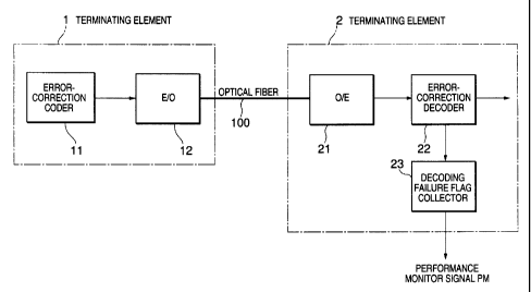
FIG. 1 is a diagram showing an optical
transmission system according to a first embodiment of the
present invention;
FIG. 2A is a diagram showing a subframe format
used in the first embodiment;
FIG. 2B is a diagram showing a frame format used
in the
CA 02325090 2000-11-03
FQ5-497 8
first embodiment;
FIG. 3 is a diagram showing an optical transmission
system according to a second embodiment of the present
invention;
FIG. 4 is a diagram showing an optical transmission
system according to a third embodiment of the present
invention;
FIG. 5 is a diagram showing a frame format used in the
third embodiment; and
FIG. 6 is a diagram showing a frame format used in the
conventional transmission system.
DETAILED DESCRIPTION OF THE PREFERRED EMBODIMENTS
FIRST EMBODIMENT
As shown in Fig. 1, it is assumed for simplicity that
an optical communication network is composed of terminating
elements 1 and 2, which are connected through an optical
fiber 100.
The terminating element 1 includes an error-correction
CA 02325090 2000-11-03
FQ5-497 9
coder 11 and an electro-optic transducer (E/O) 12. The
error-correction coder 11 uses an existing error-correcting
code such as Reed-Solomon code. The terminating element 2
includes an opto-electronic transducer (O/E) 21, an error-
correction decoder 22, and a decoding failure flag collector
23. The error-correction decoder 22 uses the same error-
correcting code as the error-correction coder 11 to perform
the error-correction decoding and generates a decoding
failure flag when the error correction fails. The decoding
failure flag collector 23 counts the number of decoding
failure flags and outputs the number of equivalent error
bytes as a performance monitor signal PM, which will be
described hereafter.
More specifically, taking as an example the case of a
transmission frame composed of multiple subframes, the first
embodiment will be described in detail.
As shown in Figs. 2A and 2B, a transmission frame is
composed of 64 subframes, each of which consists of 1-byte
overhead, 238-byte payload, and 16-error byte-correcting
redundancy code.
At the terminating element 1, a frame of signal to be
transmitted is coded by the error-correction coder 11. The
error-correction code is assumed to allow up to 8 error
bytes per subframe to be corrected. The value obtained from
the error-correction coding is inserted into the error-
CA 02325090 2000-11-03
FQ5-497 10
correcting redundancy code byte of the frame. The frame of
signal is converted into optical signal by the E/O 12 and
then is transmitted to the other end.
At the terminating element 2, when receiving the
optical signal from the terminating element 1, the O/E 21
converts the received optical signal to a corresponding
electric signal and outputs it to the error-correction
decoder 22.
The error-correction decoder 22 decodes the received
signal to produce a received frame of signal and, if error
correction fails, then a decoding failure flag is output to
the decoding failure flag collector 23. As described before,
since the error-correction code allows up to 8 error bytes
per subframe to be corrected, 9 or more error bytes cannot
be precisely corrected. When 9 or more error bytes occur,
the error-correction decoder 22 generates a decoding failure
flag. Such a decoding failure flag is collected by the
decoding failure flag collector 23 and a collection of
decoding failure flags can be used to estimate the error
state of a frame.
More specifically, when a decoding failure flag is
generated, the decoding failure flag collector 23 counts it
as, for example, 9 error bytes because a decoding failure
flag is generated when 9 or more error bytes occur. The
value obtained by multiplying the decoding failure flag
CA 02325090 2005-03-15
75372-36
11
count by 9 is outputs as the performance monitoring signal
PM. Therefore, the signal error rate after error correction
can be evaluated with less error.
SECOND EMBODIMENT
As shown in Fig. 3, it is assumed for simplicity that
an optical communication network is composed of terminating
elements 3 and 4, which are connected through an optical
fiber 100. A signal transmitted from the terminating
element 3 to the terminating element 4 has the same frame
format as that of the first embodiment.
The terminating element 3 includes an error-correction
coder 31, an electro-optic transducer (E/O) 32, an overhead
insertion section 33, and a parity calculator 34. The
parity calculator 34 performs parity calculation of a frame
before error correction coding. The overhead insertion
section 33 writes the result of parity calculation into the
predetermined overhead byte of a next frame and outputs it
to the error-correction coder 31. Operations of the error.-
correction coder 31 and the E/O 32 are the same as those of
the error-correction coder 11 and the E/O 12 in the first
embodiment.
The terminating element 4 includes an opto-electronic
transducer (O/E) 41 and an error-correction decoder 42,
which are the same as the O/E 21 and the error-correction
decoder 22 of the first embodiment. The terminating element
CA 02325090 2000-11-03
FQ5-497 12
4 further includes an overhead termination section 43, a
parity calculator 44, a parity comparator 45, and a
disparity flag collector 46.
The overhead termination section 43 terminates the
overhead of a received signal inputted from the error-
correction decoder 42 and extracts the parity check byte
from the overhead thereof. The extracted parity check byte
is output to the parity comparator 45.
The parity calculator 44 inputs the received signal
from the error-correction decoder 42 and performs the parity
calculation of the received signal to output the result of
parity calculation to the parity comparator 45.
The parity comparator 45 compares the extracted parity
check byte with the result of parity calculation to
determine whether the extracted parity check byte perfectly
matches the result of parity calculation. When all the bits
of the extracted parity check byte match those of the result
of parity calculation, that is, they perfectly match, it is
determined that no error occurs in the frame, and the
disparity flag is reset.
However, when at least one bit of the extracted parity
check byte does not match the counterpart of the result of
parity calculation, that is, they do not perfectly match, it
is determined that the error correction fails, and the
disparity flag is set. The disparity flag collector 46
CA 02325090 2000-11-03
FQ5-497 13
collects the set disparity flag to be used for frame error
estimation.
More specifically, as described before, since the
error-correction code allows up to 8 error bytes per
subframe to be corrected, a set disparity flag indicates 9
or more error bytes in a subframe. Here, the disparity flag
collector 46 counts a set disparity flag as 9 error bytes,
for example. The value obtained by multiplying the set
disparity flag count by 9 is outputs as the performance
monitoring signal PM. Therefore, the signal error rate
after error correction can be evaluated with less error.
As in the case of parity calculation of SONET/SDH, it
is possible to calculate an error rate with more precision
by using a theoretical error for interpolation of an error
rate derived from the sum of all error bits of the value
obtained by parity calculation.
THIRD EMBODIMENT
As shown in Fig. 4, it is assumed for simplicity that
an optical communication system is composed of terminating
elements 5, 6, and 7, where the terminating elements 5 and 6
are connected through an optical fiber 101 and the
terminating elements 6 and 7 are connected through an
optical fiber 102.
The terminating element 5 has the same circuit
configuration as the terminating element 3 of Fig. 3 and the
CA 02325090 2000-11-03
FQ5-497 14
terminating element 7 has the same circuit configuration as
the terminating element 4 of Fig. 3. Further, the
terminating elements 5 and 7 have a switching function that
is used to switch a path in case of occurrence of failure.
The terminating element 6 is a combination of the
terminal elements 3 and 4 of Fig. 3. More specifically, the
terminating element 6 includes a receiving circuit connected
to the terminating element 5 through the optical fiber 101,
the receiving circuit having the same circuit configuration
as shown in the terminal element 4. The terminating element
6 further includes a transmitting circuit connected to the
terminating element 7 through the optical fiber 102, the
transmitting circuit having the same circuit configuration
as shown in the terminal element 3.
In the case where a signal destined for the terminating
element 7 is transmitted from the terminating element 5, at
the terminating element 6 receiving the signal destined for
the terminating element 7, after error-correction decoding,
the decoded signal is coded by the error-correction coder
and then is transmitted to the terminating element 7. On
the other hand, when a signal destined for the terminating
element 6 itself is received from the terminating element 5,
the terminating element 6 performs the same receiving
operation as the terminating element 4 of Fig. 3.
In the communication system as shown in Fig. 4, the
CA 02325090 2000-11-03
FQ5-497 15
parity check is performed in FEC (forward error correction)
section between the terminating elements 5 and 6 and in FEC
section between the terminating elements 6 and 7 as
described in the second embodiment.
However, as described before, the terminating element 6
decodes the received signal and subsequently codes the
decoded signal to transmit it to the terminating element 7.
Therefore, the terminating element 7 cannot obtain any
information about error-correction decoding failure
occurring at the terminating element 6.
According to the third embodiment, in order to provide
the terminating element 7 with information about error-
correction decoding failure occurring at the terminating
element 6, a parity check byte for a switching section
between the terminating elements 5 and 7 is inserted into
the predetermined overhead of a frame in addition to the
parity check byte for the FEC section as shown in Fig. 5.
Referring to Fig. 5, a transmission frame transmitted
in FEC sections and switching section as shown in Fig. 4 is
composed of 64 subframes, each of which consists of 1-byte
overhead, 238-byte payload, and 16-error byte-correcting
redundancy code. In this example, the parity check byte for
monitoring FEC section is written in the overhead of the
subframe #3, and the parity check byte for monitoring the
switching section is written in the overhead of the subframe
CA 02325090 2000-11-03
FQ5-497 16
#5.
As described before, when the terminating element 6
receives a signal destined for the terminating element 7,
the received signal is decoded and then the decoded signal
is coded by the error-correction coder. Accordingly, when
the error correction decoding fails, the decoded signal
including byte errors is coded as it is by the error-
correction coder to transmit it to the terminating element 7.
At this stage, the result of parity calculation in the frame
becomes different from the parity check value inserted in
the overhead at the terminating element 5. This disparity
is not eliminated even if the error correction is performed
at both the terminating elements 6 and 7. Therefore, by
comparing the parity check value inserted in the overhead
with the result of parity calculation, the terminating
element 7 can determine whether a transmission error occurs
somewhere between the terminating elements 5 and 7. In this
manner, as in the case of the second embodiment, the
transmission error evaluation can be performed.
Although the above-mentioned embodiments of the present
invention have been described herein, it should be apparent
to those skilled in the art that this invention may be
embodied in many other specific forms without departing from
the spirit or scope of the invention. Therefore, the
present examples and embodiments are to be considered as
CA 02325090 2000-11-03
FQ5-497 17
illustrative and not restrictive and the invention is not to
be limited to the details given herein, but may be modified
within the scope of the appended claims.