Note: Descriptions are shown in the official language in which they were submitted.
CA 02325204 2005-04-05
'° METHOD TO CHARACTERIZE THE PROSPECTIVE OR ACTUAL LEVEL
OF INTERFERENCE AT A POINT, IN A SECTOR AND THROUGHOUT A
CELLULAR SYSTEM
BACKGROUND OF THE INVENTION
Field Of The Invention
This invention relates to cellular telephone systems and, more particularly,
to
processes for designing and improving the performance of cellular telephone
systems.
History Of The Prior Art
Presently available commercial mobile communication systems typically include
a plurality of fixed base stations (cells) each of which transmits signals to
and
receives signals from mobile units within its communication area. Each base
station is assigned a plurality of channels over which it can communicate with
mobile units. A mobile unit within range of the base station communicates with
the external world through the base station using these channels. Typically,
the
channels used by a base station are separated from one another sufficiently
that
signals on any channel do not interfere with signals on another channel used
by
that base station. To accomplish this, an operator typically allots to a base
station
a group of channels which are each widely separated from the next. So long as
a
mobile unit is within the area in which the signal from a base station is
strong
enough and is communicating with only that base station, there is no
interference
with the communication.
1
CA 02325204 2000-11-02
In order to allow mobile units to transmit and receive telephone
communications as the units travel over a wide geographic area, each
cell is normally physically positioned so that its area of coverage is
adjacent to and overlaps the areas of coverage of a number of other cells.
s When a mobile unit moves from an area covered by one base station to
that covered by another, communication with the mobile unit is
transferred (handed oft) from one base station to another in an area
where the coverage from different cells overlaps. Because of this
overlapping coverage, the channels allotted to the cells are carefully
selected so that adjoining cells do not transmit or receive on the same
channels. The channels used by adjoining base stations are also
theoretically separated from the channels of each adjoining base station
sufficiently that signals from any base station do not interfere with
signals from another adjoining base station. This separation is typically
15 accomplished by assigning a group of widely separated non-interfering
channels to some central cell and then assigning other groups of widely
separated non-interfering channels to the cells surrounding that central
cell using a pattern which does not reuse the same channels for the cells
surrounding the central cell. The pattern of channel assignments
2o continues similarly in the other cells adjoining the first group of cells.
The pattern is often called a channel reuse pattern.
So long as a mobile unit is within the area in which the signal from a
base station is strong enough and is communicating with only that base
station, there is no interference with the communications. However,
2s when a mobile unit moves from an area covered by one base station to
that covered by another base station, the communication must be
2
CA 02325204 2000-11-02
transferred from one base station to the other in an area. This requires
cell coverage to overlap. Because of this overlapping coverage, the
channels allotted to the cells are carefully selected so that adjoining cells
do not transmit or receive on the same channels.
s There are a number of different types of mobile communications systems.
Channels are defined in different manners in each of the different
systems. In the most prevalent American Mobile Phone System (AMPS)
system, channels are defined by frequency. A frequency band of25 MHz
providing approximately four hundred different adjoining FM frequency
1o channels is allotted by the federal government to each cellular operator.
In a typical AMPS system, each channel uses a fixed FM frequency band
width of 30 KHz. for downlink transmission from a base station to a
mobile unit and another fixed FM frequency band width of 30 KHz. for
uplink transmission from a mobile unit to a cell. Typically, the
1s frequencies assigned to the downlink transmissions for an entire cellular
system immediately adjoin one another and are widely separated from
the frequencies assigned to the uplink transmissions which also
immediately adjoin one another. In this specification, even though
widely separated, the pair of frequencies used for both downlink and
20 uplink transmission are generally intended when reference is made to an
AMPS channel unless the context indicates otherwise.
Since channels are defined by frequency in an AMPS system, the
channels used by any single base station are separated from one another
in frequency sufficiently to eliminate interference between those
2s channels. An operator typically allots a base station a set of channels
with frequencies which are each separated from the next by some large
3
CA 02325204 2000-11-02
number (e.g., twenty-one) channels carrying intermediate frequencies.
Thus, in a system with twenty-one channel separation, one base station
might use channels 1, 22, 43, 64, 85, and so on up to a total of between
five and one hundred individual channels.
s When a mobile unit moves from an area covered by one base station to
that covered by another base station in an AMPS system, the
communication must be transferred from one base station to the other in
an area in which cell coverage overlaps. Because of this overlapping
coverage, the channels allotted to the cells are carefully selected so that
adjoining cells do not transmit or receive on the same frequencies. This
is typically accomplished by assigning channels to a central cell which
are widely separated in frequency in the manner described above, and
then assigning channels to the cells surrounding that central cell using a
pattern which increases each channel number by one for each sequential
is cell surrounding the central cell. Thus, if cells are arranged in a
honeycomb pattern in which six cells surround a central cell using the
above-described channels, a first cell adjacent to the central cell may
have channels 2, 23, 44, 65, 86, and so on while a second cell adjoining
the central cell may have channels 3, 24, 45, 66, 87, and so on. The
2o pattern of channel assignments continues similarly in the other cells
adjoining the central cell.
In some AMPS systems, especially those with cells in urban areas
carrying heavy traffic, each cell may be further divided into two or three
sectors each of which may include channels having the above-described
2s frequency allotment of channels. The antennas of each sector are
typically arranged to provide 180 or 120 degree coverage. When cells are
4
CA 02325204 2000-11-02
discussed herein, sectors are normally meant as well unless the context
indicates otherwise.
Another type of mobile system called Code Division Multiple Access
(CDMA) uses digital signals to transmit data. All of the base stations of a
s CDMA system use the same "spread spectrum" frequency band of 1.25
megacycles to transmit the digital signals. The transmissions are
combined with redundant channel coding information to allow error
correction. The encoded signals are then multiplied by one of sixty-four
Walsh codes which establish individual channels and increase the
bandwidth to 1.25 megacycles. Because of the redundancy of the
encoded signals, a receiver may decode a signal from the plethora of
coded channels carrying data on the broad frequency band. Since the
Walsh codes establish a number of individual channels and the pseudo-
noise code assigned to each base station differs from those of other
15 surrounding base stations, adjacent and remote cells may reuse the
same frequency bands.
In another common type of mobile system called Time Division Multiple
Access (TDMA), frequencies are assigned to the entire system in groups
much like they are assigned in an AMPS system. However, within any
2o frequency, each base station sends and receives in bursts during some
number of different intervals or time slots. These time intervals within
frequency bands then effectively constitute the individual channels. By
assuring that the group of frequencies assigned to any individual base
station differ from one another and from the frequencies assigned to base
25 stations surrounding each individual base station, a channel reuse
CA 02325204 2000-11-02
pattern is established which allows substantially greater use of the
frequency spectrum because of the time division process.
In theory, these forms of cell arrangement and channel assignments
allows channel reuse patterns to be repeated at distances separated
s sufficiently to negate interference between mobile units on the same and
adjacent channels.
Unfortunately, interference does occur for a number reasons. Antenna
patterns, power levels, scattering, and wave diffraction differ from cell to
cell. Buildings, various other structures, hills, mountains, foliage, and
to other physical objects cause signal strength to vary .over the region
covered by a cell. Consequently, the boundaries at which the signal
strength of a channel falls below a level sufficient to support
communications with a mobile unit vary widely within a cell and from
cell to cell. For this reason, cells adjacent one another do not, in fact,
1s typically form the precise geometric boundaries suggested above. Since
cell boundaries must overlap to provide complete coverage of an area and
allow handoff and because the boundaries of cells are imprecisely
defined, signals will often interfere with one another even though they
are generated by cells which are at distances theoretically sufficient to
2o eliminate interference. This is especially true when a sectored cell
pattern is used because the cells are much closer to one another than in
a simple cell pattern.
A first signal on a channel from a remote cell interferes with a second
(usually) stronger signal carrying a mobile transmission on the same
25 channel within the coverage area of a cell when the drop in strength of
6
CA 02325204 2000-11-02
the first signal from the second signal is less than some threshold level
(typically measured in decibels). A signal from another cell on a channel
at a frequency adjacent the frequency of a channel carrying a mobile
transmission interferes when the drop in strength of the interfering
s signal from the serving signal is less than some second threshold level.
The values are determined by the particular type of mobile system
involved. For example, in an AMPS system, a signal on the same
channel (co-channel) from a remote base station interferes with a desired
carrier signal if the interference level is not 18 dB lower than the desired
carrier; and a signal on an adjacent channel from another base station
interferes with a desired carrier signal if the interference level is not 6 d8
lower than the desired carrier. For a CDMA system, an interfering signal
must be more than 14 d8 stronger than the carrier to obscure a carrier
signal because the codes establishing the channels establish heavily
t5 redundant signals from which patterns may be extracted even though
the interfering signal is stronger.
In order to determine whether interference exists, a mobile system
operator typically relies on customer complaints. When customers
register a sufficient number of complaints regarding communicatiori at
2o particular points in a system, an operator will usually conduct a
relatively expensive field test of the suspected portion of the system to
measure carrier signals and interference received. During the test, the
portion of the system in which the tests are conducted is essentially
disabled. Because of the expense and inconvenience, the tests are
25 typically limited only to the suspected area. Because such tests are
limited to determining the interference at those points at which a system
CA 02325204 2000-11-02
operator expects to find interference, the efficacy of these tests is very
suspect.
The tests provide data from which the points at which channels from
different cells actually interfere with one another may be determined. If
s the level of interference is sufficiently large, the operator may change the
channel group assigned to the particular area. That is, the frequency
group assigned to a cell (or cells) may be changed in its entirety to
another frequency group in which channels which would interferE with
channels carried by other cells do not exist. It is also possible to
eliminate some interference by changing cell characteristics (such as
antenna tilt or power used in particular cells) without changing the
channels used. Once channels have been assigned to cells which provide
acceptable coverage and detected interference has been eliminated, the
system is fixed and operated until other complaints arise.
15 A major problem with the process is that it does not provide a complete
understanding of interference which actually exists in a system since
typically only those positions at which extensive interference has been
reported are tested for actual interference. The process does not take
into consideration all of the possible signals which might be propagating
2o into the affected area to interfere with the carrier nor does it take into
consideration the effects which a change in channel assignments may
have in other areas of the system. Often (and possibly usually) this
method of curing interference merely exports the interference to another
portion of the system where it is only discovered when a sufficient
2s number of complaints arise to warrant a field test of the newly isolated
area of interference.
8
CA 02325204 2000-11-02
Moreover, this method of placing cells, assigning frequencies, and
eliminating interference is quite slow and labor intensive. Testing a
medium sized system may require as much as 400 man hours. The
process greatly increases the costs of creating and maintaining mobile
systems without guaranteeing that interference will be eliminated.
Because of the emerging nature of the market for cellular telephones,
system changes which cause interference such as traffic growth are
taking place constantly and at an accelerating rate. Complicating the
general problem of interference in an existing system is the fact that
to cellular system operators are presently installing new CDMA and TDMA
systems because they allow a greater number of mobile units to utilize a
system and because these digital system provides a better quality of
service when they are functioning properly. Often the installation of
these new systems is taking place where AMPS cellular systems already
exist and will continue to exist. In general, with these systems, some of
the frequencies used in the AMPS systems are removed; and a CDMA
base station is positioned in place of a sector at a base station.
It is desirable to provide a process by which the quality of service
provided by a cellular system (and portions thereof) may be determined
2o in terms of fixed verifiable quantities so that changes may be made to
enhance the quality of service with an expectation that the changes will
have the desired result in actually improving the quality of service
provided by the system.
9
CA 02325204 2000-11-02
Summary Of The Invention
The present invention is realized by a computer implemented process
which compares signals communicated between a known position and a
plurality of base stations in a cellular telephone system to determine the
level of interference with a signal on a channel expected to serve the
known position, and determines a value indicating a probability of
interference with a signal on a channel expected to serve the known
position. _
In one embodiment, changes in the system to improve the interference
1o value are implemented only if the interference value is above a certain
level.
These and other features of the invention will be better understood by
reference to the detailed description which follows taken together with
the drawings in which like elements are referred to by like designations
is throughout the several views.
Brief Description Of The Drawin»s
Figure 1 is a drawing depicting an idealized mobile cellular
telecommunications system.
Figure 2 is a drawing depicting a portion of a more realistic mobile
2o cellular telecommunications system than that illustrated in Figure 1.
Figure 3 is a graphical view illustrating the effect of signals interfering
with carrier signals useful in understanding the method of the invention.
CA 02325204 2000-11-02
Figure 4 is a flow chart illustrating a portion of a process in accordance
with the present invention in a system such as that illustrated in Figure
1.
Figure 5 is flow chart illustrating another portion of a process in
s accordance with the present invention in a system such as that
illustrated in Figure 1
Detailed Description
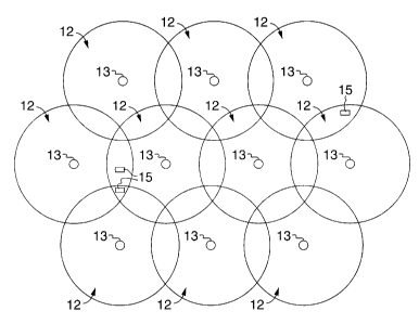
Referring now to Figure 1, there is illustrated a cellular telephone system
which includes a number of individual cells 12 arranged in an
to idealistic honeycomb pattern. For the purpose of this explanation of the
invention, the system 10 will be considered to be an AMPS system. This
invention may be practiced, however, with any of the known cellular
systems including CDMA and TDMA systems. More particularly, the
signal strength data accumulated in constructing a narrow band system
is such as an AMPS or TDMA system may be used to construct or improve
a CDMA or other wide band system. The data accumulated from an
AMPS system differs from that of a CDMA system only with respect to the
effect of Rayleigh fading; and the effect of Rayleigh fading cancels out
with a sufficient number of redundant points of measurement. In a
2o similar manner, the data accumulated from a CDMA system may be
utilized to construct or improve an AMPS system.
In an AMPS system, each of the cells 12 includes at least one base
station 13 which transmits and receives communications on a number of
assigned frequencies with mobile units 15 operating within its service
25 area. The frequencies which are chosen are separated sufficiently that
11
CA 02325204 2000-11-02
signals from any single base station do not interfere with other signals
from that base station. In Figure 1, the service area of each of the ideal
cells 12 is defined by an outer solid boundary which indicates the limits
of the area in which the signals from that cell 12 are strong enough to
s serve a mobile unit 15.
As may be seen in Figure 1, in order to allow mobile units to transmit
and receive telephone communications over a wide area, the service area
of each cell 12 overlaps the service areas of a number of adjacent_cells 12
so that within these overlapping areas either of two or more cells 12
might serve a mobile unit 15. The channels allotted to the individual
cells and the frequency reuse pattern are carefully selected so that
adjoining cells do not transmit or receive on the same frequencies.
Consequently, there are no overlapping areas over an entire cellular
system in which signals of the same frequency are received
15 simultaneously from more than one cell 12 by a mobile unit 15.
In some systems, cells used in areas carrying heavy traffic are further
divided into two or three sectors each of which may include channels
allotted as described earlier. The antennas of each three sector cell are
arranged to provide 120 degree coverage. With slightly over four
2o hundred channels available to each cellular system, this allows a
repeating pattern of groups of cells in the beehive arrangement of Figure
1 with seven cells each having three sectors each of which has
approximately twenty channels.
Unfortunately, the boundaries at which the signal strength of a channel
2s falls below a level sufficient to support communications with a mobile
12
CA 02325204 2000-11-02
unit vary widely from cell to cell. For this reason, cells adjacent one
another do not, in fact, typically form the precise geometric boundaries
suggested above but form a boundary patterns such as those illustrated
in Figure 2.
s Since it is necessary that each cell 12 (or sector of a cell 12 if the cell
is
divided into sectors) have sufficient power to transmit and receive signals
with a mobile unit 15 in the overlapping areas of cell coverage to
accomplish hand-off of a mobile unit transmission from one cell.~o
another, it is possible that channels used by different cells will interfere
to with each other. As has been pointed out, channels which may interfere
with one another are channels using the same frequency (co-channels)
and channels on frequencies immediately adjacent to a serving channel.
Thus, in assigning cell sites and establishing a reuse pattern, the
operator attempts to assure that channels which might interfere with one
is another are not present in overlapping areas. This is relatively simple
given the ideal system such as that illustrated in Figure 1.
However, in the more realistic system illustrated in Figure 2, it will be
seen that areas covered by different cells overlap not only where the cell
sites are immediately adjacent one another but at greater distances. For
2o example, coverage provided by cell 4 (in Figure 2) is overlapped by
coverage provided by each of adjoining cells 1, 2, 3, 5, 6, and 7. This
overlap is normal and allows hand-off to occur when a mobile unit moves
from the area covered by cell 4 to any of the immediately adjoining areas
of coverage. However, coverage provided by cell 4 is also overlapped by
25 non-adjoining cell 8. If the cells of Figure 2 are divided into sectors
each
covering 120 degrees, then the frequencies of channels assigned to the
13
CA 02325204 2000-11-02
overlapping areas in adjoining cells may cause adjacent channel
interference. Moreover, because of the limited number of channels
available, the sectors of cell 8 may be assigned channels which cause co-
channel interference with the channels of cell 4 in a typical frequency
s reuse pattern. Similar interference problems exists with respect to other
cells in the cellular system which are not shown in Figure 2.
Because the coverage offered by different cells differs so drastically, a
cellular system is usually established using software which predicts what
signal strengths are to be expected from each of a particular set of cells.
1o This software uses input data describing the general physical
characteristics of the terrain surrounding each cellular site and the
physical characteristics of the cellular station to generate estimated
signal strength coverage plots for the area surrounding a cellular site.
This predictive software is used to determine antenna positions which
1s should provide optimum coverage with minimum interference in a typical
system. However, since the predictive software used to establish a
system presumes general characteristics derived from similar terrain and
similar cells to determine cell coverage, overlap such as the overlap of
cell 8 into the boundaries of cell 4 illustrated in Figure 2 is often not
2o predicted. In fact, it has been found that the total prediction error in
comparing the strengths of the carrier signal and interference utilizing
such prior art predictive software is approximately plus or minus 13.6
dB. Since a carrier signal should be 18 dB greater than an interfering
signal in order to eliminate co-channel interference in an AMPS system,
25 this is a very large discrepancy.
14
CA 02325204 2000-11-02
Once cell sites have been determined in some manner (e.g., using
predictive software), the operator assigns channel groups to the cells in
accordance with the technique described above, places antennas in
position, and operates the system. Unless interference is suspected or
s immediately apparent, the operator waits for subscriber complaints to
surface and then conducts physical tests at positions limited to the
positions of the complaints to determine whether interference, in fact,
occurs at those positions. The determination of actual interference is
made by drive tests which measure signal strength of channels at the
1o positions where interference is suspected or complaints have shown that
interference has occurred within the cellular system area. I Conducting
signal to interference measurements is very labor intensive, so strength
measurements are typically taken only at points where interference is
expected. These tests may entirely miss interference which actually
15 occurs.
If the tests show that interference is sufficiently great at the positions of
the measurements, the groups of channels assigned to the cells having
interfering channels may be changed. Determining whether interference
is sufficiently great is accomplished by comparing at any point the level
20 of interference to the signal level of the carrier. Acceptable levels have
typically been chosen to be those described above, i.e., l8dB for co-
channel interference and 6 dB for adjacent channel interference in an
AMPS system. If interference of this level is ultimately found to exist in
an area which is expected to carry significant traffic, the frequency group
2s assigned to a cell (or cells) is typically changed in its entirety to
another
frequency group which does not have channels which would interfere
CA 02325204 2000-11-02
with channels carried by the surrounding cells. If this does not work,
changing cell characteristics such as antenna tilt or the radiated power
may eliminate interference without changing the groups of channels
used. Once channels which provide acceptable coverage have been
s assigned to cells and the previously detected interference has been
presumed to be eliminated by this method, the system is fixed and
operated.
This operation is slow, labor intensive, and often does not provide a
complete resolution of the problem. For example, changing frequency
to assignments may simply transfer interference problems unexpectedly to
other areas of the system by transferring coverage such as that shown
for cell 8 in Figure 2 to unexpected areas.
A method has now been devised which overcomes the problems of the
prior art by utilizing measured signal level data for an entire system to
is provide predictive plots which may be utilized to establish cell site
positions and channel assignments. The process allows plots and
channel assignments to be easily changed at minimal cost whenever a
system undergoes change.
In one embodiment, the process begins with a drive test of the entire
2o system area. In the drive test for this embodiment, each cell and sector
transmits on a single channel different than any channel used for
transmission by any other cell or sector in the area. In general, signals
on all channels transmitted from any one cell are, on an average,
received at the same strength at any given point in the service area so
2s long as the frequencies of the channels are within approximately ten
16
CA 02325204 2000-11-02
percent of each other. Thus, whatever channel a cell transmits on
during the tests, the received signal strength will be the same for signals
transmitted on any other channel from that cell.
If an entirely new system is being designed, expected cell sites may be
s selected in any of a number of different ways such as by use of prior art
predictive plotting software; and then test transceivers may be placed at
the proposed cell site positions. If a cellular system already exists, then
the cell sites which exist are used along with any proposed new eell sites.
A mobile unit with a scanning receiver drives over all of the roads and
to highways of the entire system. The mobile scanning receiver constantly
scans and measures the strength (usually received signal power) of each
test channel transmitted from each of the cell sites as the mobile unit
moves. The mobile unit also includes equipment (such as Loran or
Global Positioning System (GPS) equipment) which constantly records
is the position of the mobile unit as each set of strength measurements is
taken. This provides strength measurements of frequencies generated by
transmitters at all of the cell sites proposed to be included in the system
which can be received at each point in the service area over which the
mobile unit drives. By transmitting from each cell on a single different
2o channel, the cell which is transmitting any signal received at any point
by the mobile unit is positively known. As the test continues, the signal
strength measurements of all signals received (or all signals greater than
a certain level) are recorded in a database by equipment in the mobile
unit together with the position at which the signals were received .
2s It should be noted that certain interference, typically Rayleigh fading, is
essentially intermittent in nature. Such interference tends to strengthen
17
CA 02325204 2000-11-02
and weaken received signal strength over very short distances. In order
to eliminate the effect of this intermittent fading, readings may be taken
at a number of positions quite close together and later averaged in order
to provide quite an accurate representation of the strength of signals
s received at any point. In one embodiment, each data sample is combined
with other data samples within one hundred feet of each other to
eliminate the intermittent effects and normalize samples taken during
different test drives. Since Rayleigh fading is the primary difference
between received signal strengths in different types of mobile systems,
the data gathered from tests conducted in narrow band systems may be
used in the design or improvement of wideband systems.
The frequency of each piece of signal strength data in the database is
then related to the test channel being transmitted by each cell and sector
during the test. This generates a database which indicates the cell and
is sector from which each signal received by the mobile unit was sent. The
cellular strength data base thus includes actual, rather than projected,
received signal strengths at each point in the test area for signals
transmitted from each cell.
It should be noted that the signal strength data for an area can be
2o compiled from more than a single drive test. In such a case, the data
from all of the drive tests must be combined so that the data of each
drive test matches that of other drive tests. Thus, for example, if higher
transmission power was used in one drive test than in another, then the
strength values should be scaled to provide data having the same
2s significance. The data collected from one drive test may also be
"combined" with previously collected data from other drive tests if the
18
CA 02325204 2000-11-02
new data represents only a portion of the cells in the network. Of course,
if data is already available from previous wide area test drives, then this
data may be used and no test drives need be conducted. This step is
useful when adding new cells to a network so that the effect of new cells
may be determined without having to re-collect data for the entire
network.
A second method of collecting signal strength data provides substantial
economies over the method explained above, especially when nevi sites
are being planned and a particular site has not yet been selected. Tests
to have shown that the signal strength received at a cell site from the
mobile transmitter in an uplink transmission is on an average the same
as the signal strength which would be received at a mobile unit from a
cell site in a downlink transmission. If the uplink and downlink signal
strengths differ, comparable values may be obtained by adjusting the
1s amplifications and power values. Thus, rather than conducting drive
tests with transmitters placed at each proposed cell site as in the first
method and checking each against the other, drive tests are conducted
by placing a single transmitter in a mobile unit and using fixed receivers
(rather than expensive scanning receivers) at all of the proposed
2o positions at each of the sites over an area for which new cells are
proposed. The mobile unit drives over the roads encompassed by the
new cells transmitting on a single frequency while all of the receivers
attempt to detect the transmission. The power level transmitted by the
mobile antenna is measured at the mobile unit, and a positioning system
25 is linked to the mobile unit to provide position indications at each point
of measurement. The mobile transmitter sends a signal at the selected
19
CA 02325204 2000-11-02
frequency, and the receivers at all of the cells measure its strength. The
position of the mobile unit for each of the test transmissions is recorded
with the times of the transmissions in a database. The signal strength
received at each proposed site and the times of reception are recorded by
each receiver. Since the signal strength received at a cell site from the
mobile transmitter in an uplink transmission is on an average the same
as the signal strength which would be received at a mobile unit from a
cell site in a downlink transmission (or may be adjusted to be so), the
data gathered by the drive test using this second method may be directly
to substituted for the data gathered in the drive tests for the previous
method.
Once the data is available, however it has been collected, the process
compares the data for each channel received at each point in the entire
area with the data for all other channels received at the point to
is determine at any point which cells should serve the point. These cells
are called "likely servers." A number of criteria may be used.
In general, a cell is a likely server at a particular location if there is a
non-trivial probability that a cell will provide a transmission path to or
"serve" a mobile unit at that location. Different methods may be used to
2o determine likely servers. A basic method identifies as likely servers all
cells that serve a location with a signal strength within 3 d8 (or some
other value depending on the system) of the strongest signal strength for
that location. More sophisticated methods may account for signal path
imbalances, may balance the uplink and downlink strengths where they
2s vary, may bias certain strength determinations in favor of particular
cells, or provide other adjustments to match the particular area of the
CA 02325204 2000-11-02
system. The method may also account for each different type of network
hardware and network configuration and control information (e.g. how
mobile unit hand-off is performed) to determine likely servers for each
location.
s Using the basic method, the cell providing the strongest signal at a point
is typically designated the cell to serve that point because signals on any
channel on which the cell transmits will be received at approximately the
same signal strength. Signals on other channels received at the same
point but at lesser strengths still within the 3 d8. range typically are
to transmitted by adjoining cells in what constitutes a hand-off (overlap)
area for that point. The service area for each such cell is ultimately
determined by applying the planned power, path imbalance, and handoff
parameters to the test data which has been accumulated.
Once the cells serving all of the points of a service area are known, the
is group of channel proposed for each of the cells or sectors is associated
with those cells. When the channels for each cell are known, the signal
strength provided by each cell which is the server at each test position in
the cellular system is compared with the signal strengths of all cells
transmitting signals received at each test position which transmits on
2o channels which could cause co-channel or adjacent channel interference.
This allows a determination of whether the proposed channel selection
causes either co-channel or adjacent frequency interference at any point
in the system. Since the points at which signals on any particular
channel transmitted by one cell will have a certain strength and may
2s interfere with signals from another cell may be determined from the
signal strength data which has been collected, such a determination may
21
CA 02325204 2000-11-02
be made for each proposed point and channel in the system. Whether a
signal will interfere is usually determined by subtracting the interfering
signal strength in d8m from the signal strength of the carrier signal
serving the point in dBm at each point. The cells which are likely servers
s at each point have already been determined from the test to determine
cells serving a point. For co-channel interference in the AMPS system, if
the difference is less than 18 dB, interference exists. For adjacent
channel interference in the AMPS system, if the difference is less than
from 3 to 6 d8. (depending on the criteria used), interference exists. If
to there is interference at any point in the system, the pattern of channel
assignments and other cell configuration information (such as effective
radiated power (ERP)) may be changed; and the actual signal strength
database may be run against the new cell channel assignments. This
requires no new testing or other operations by the operator; it requires
15 simply running the software until channel selections which exclude
interference are determined.
Not only may the process be used to update or plan a new system, the
process also allows signal strength measurements derived from drive
tests conducted using a particular type of cellular system such as an
2o AMPS to be used for determining coverage and interference patterns for
cell sites utilized by entirely different types of systems. This has the
advantage of allowing drive test results accumulated from an older
system to be used to predict interference which may occur in newer types
of systems which might be installed at the same sites. The same signal
2s strength test results may be utilized as a system is changed in any
manner. In a similar manner, if an operator has already established
22
CA 02325204 2000-11-02
CDMA channels from which the strength of signals may be discerned, it
is possible to use this data to optimize the performance of the AMPS
channels which exist at the same cell site. An additional benefit is that
the CDMA measurement process is non-invasive so that the operator
s does not have to key-up" channels for testing to derive data.
In an AMPS system, the new channel assignments may be tested by the
software against the signal strength measurement database to derive
new predictions of interference. If additional cells or sectors are to be
added, this may be accomplished by drive tests for signals from the new
to cells only. These may be added to the signal strength measurement
database and the updated database used to determine new channels to
be used.
It has now been determined that this process may be made substantially
more useful by modifying the process to provide consistent values which
1s indicate just how the various points, sectors, and cells in the system,
and the system itself compare with other points, sectors, cells, and
systems. Such a value is more readily understood by system operators
and allows changes to be planned with an understanding of the result
which will be accomplished by those changes.
2o In order to generate values which have meanings which remain
consistent wherever they are determined, the improved process relates
not only the strengths of carrier signals and signals which interfere with
those carrier signals but also determines the probability of occurrence of
the various interfering signals and the severity of the interference during
2s receipt of the interfering signal. This allows an interference value to be
23
CA 02325204 2000-11-02
determined which essentially indicates the percentage of time a
subscriber to a mobile system may expect to encounter perceptible
interference at any point in the system. Moreover, the interference
values for points within a sector, cell, and system may be accumulated
s and averaged in the manner described in Figure 4 to provide an
interference value for sectors, cells, and the system. This allows an
operator to pinpoint sectors and cells which need to be improved and
provides an overall evaluation of a system from which an operator may
determine rationally whether improvements need to be made. Using the
1o interference values for points in a system, the efficacy of each change to
the system may be evaluated as it is proposed. Each type ~ of change
which might be made may be compared to other types of changes in
order to make the most economical changes possible.
To understand how a consistent interference value may be derived, the
is process of interference has been dissected to determine its elements. For
example, if it is possible that three different signals may interfere with a
particular signal from a base station which is a most likely server, then
the actual likelihood of each of these signals interfering can be
considered in order to better understand how receipt of signals at that
2o point compare with receipt of signals another points and thus to have an
idea on how to improve a system. This is accomplished by the use of a
probability number assigned to each of the different interfering signals
determined from the traffic patterns and other factors known (or
estimated) to occur for the particular base stations. A cell in an area
2s having more traffic transmits during a greater portion of the time
spectrum.
24
CA 02325204 2000-11-02
Figure 3 illustrates a plot of co-channel interference ratios (carrier
strength of signal from a primary server divided by signal strength of a
co-channel signal received) versus the effect those ratios have on
transmission of a earner signal in an AMPS system. The effect is shown
as a weight value which indicates the severity of the interference. As
may be seen, if the co-channel interference is great enough so that the
difference in signal strength is less than approximately 10 dB, then the
interference is too great for any useful transmission. Such an
interference level is given a weight of one. On the other hand, if the
signal strength of a carrier signal is more than 18 dB greater than the
signal strength of the interfering co-channel, then the effect on the
transmission is nil; and a weight of zero is given. Between these values,
the interfering signal has greater and lesser effects as may be seen from
the figure.
In one embodiment of the invention, the presumption is made that if two
or more signals may possibly interfere with a carrier at any point in the
system, the effect of the stronger interfering signal will negate any effect
that the weaker signals may have during time the stronger signal is being
received. Although this is an approximation, its use has little affect on
2o the accuracy of the results produced. The use of this presumption
means that only the stronger interfering signal need be considered at any
time. Thus, to determine the overall effect of three interfering signals,
the probability of the occurrence of each signal is determined and then
multiplied by the weight value to determine the effect that signal has.
For example, a strongest interfering signal within 10 dB of the carrier
has the weight one (indicating that the carrier signal is entirely obscured
CA 02325204 2000-11-02
during transmission of the interfering signal) multiplied by the
probability of occurrence. Thus for the 2 d8 signal shown in Figure 3, its
probability is 0.4; and its effect is obtained by multiplying this
probability by the weight of one.
s Once the effect of the strongest interfering signal has been determined,
its probability of transmission is subtracted from one to provide the
probability that the first interfering signal is not active. The result of
this
computation provides the time range within which the second strongest
interfering signal occurring will have significant effect. Thus, the
to probability that the second strongest signal of 12 d8 will interfere is the
probability factor 0.6 of the second signal occurring multiplied by the
time during which it will have significant influence (0.6 of the total time).
This probability for the second signal is multiplied by its weight of 0.84
to determine its effect. The probability that the third signal of 15 dB will
15 interfere is determined by multiplying the probability that the first
interfering signal is not active by the probability that the second
interfering signal is not active by the probability factor for the third
signal occurring. This probability factor is then multiplied by the weight
of 0.32 for the third signal to reach an effect for the third signal.
2o Adding the effect of all of these signals interfering provides a final
result
of 0.7408 which may be stated as a percentage and provides a quality
number for the particular point in the system with the planned channels
and parameter settings. In essence, the interference value indicates the
percentage of time interference will be present at the point. Obviously,
25 the value of 74% indicates that receipt of signals at the particular point
26
CA 02325204 2000-11-02
is almost impossible. This interference or quality value may be compared
with interference values for all other points in a service area.
Once a quality value for a point has been obtained, quality values are
obtained for some number of additional points in the sector sufficient to
s provide a relatively good evaluation of all of the places in the sector at
which communications may be received. The quality values obtained for
a sector are then added together and divided by their number to obtain
an average quality value for the sector (or cell). Figure 4 illustrates the
method by which this is accomplished, finding first an interference value
to for a point, then a next point, and so on until the points for a sector are
all determined. Then all sectors values are determined and finally a
sector score is reached.
Similarly, once the quality value for one sector has been obtained, quality
values for all sectors in a system may be similarly obtained, added
15 together and averaged to provide a quality score for the entire system.
This score may then be utilized to determine whether the system should
be changed in order to provide improved service. Utilizing a quality value
which is consistently applied from point-to-point, sector-to-sector, and
system-to-system allows a valuation to be made from which some real
2o determination of quality may be made.
More specifically, if a quality valuation for a sector is known, it is
possible to determine whether changes which might be attempted in the
system would be successful. That is, different changes to a particular
sector may be assigned different quality increments by testing to
25 determine the effect those changes might have. For example, changing
27
CA 02325204 2000-11-02
the power level of an interfering signals from another sector can clearly
be ascribed an increment since the level of signal received is an exact
value in reaching the original interference level. With an incremental
value to be applied for a change to the sector, it may be known before
any change is made whether that change will provide an improvement in
the sector and system quality.
Figure 5 is a flow chart which illustrates the operation of the method to
improve the quality of a system once a quality value for the sectors and a
system are found and the values of possible changes are known. As may
to be seen, the method begins with the original interference value for a
point, and selects a best change to improve the quality of service for the
point. Often when beginning to improve a system, this best change is a
change in the group of frequencies assigned to one or more sectors (or
cells). Probably the next change to be made once appropriate frequency
groups have been chosen, is to change power settings of transmitters.
Biasing the level of handoff so that the handoff occurs if two channels
are within two, three, or four dB of one another in a handoff area
changes the point at which handoff occurs and the level of power
necessary in those areas. Other changes which are possible include
2o changing antenna types, and other changes related to equipment
modification.
The method illustrated in Figure 5 may be used in more than one
manner. It may be used to iterate through changes of one type (e.g.,
change the frequency assignments) computing each result as it is
implemented in software until an interference value is reached which is
the best that that form of change can accomplish. Alternatively, it may
28
CA 02325204 2000-11-02
be used to select among different types of changes to determine which
provides a better result when compared to the cost of implementing the
change.
Presuming for the moment that the change is an iteration through a
s selection of possibilities of one type (frequency groups), until a best
result
is reached, a list of changes is prepared by comparing the interference
levels at each point to determine which frequencies interfere with one
another. A particular change is selected from the list of possible_
changes, and a determination is made by running the software whether
to the change produces a result greater than some value so that the change
is worth undertaking for the improvement to be expected. When testing
different frequency groups, the change making the process worth while
may be a reduction of some percent (e.g., one percent) in the interference
value. Changing frequency groups, changing power levels, or biasing the
1s handoff level differently usually costs nothing but processing time and is
worth while if it produces a concrete result. Other changes may require
new equipment and be more expensive, however.
If the change contemplated does not produce an improvement sufficient
to warrant its use, the change may be thrown out and a final interference
2o value determined. If the change is worth making, the list of changes is
updated to show that the particular change has been evaluated and the
amount of change is listed in a list of changes. The change is added to a
list of changes to make as a best change if it is the first or best tested. It
is also listed as the best change to make. The process then iterates
25 through the list and for each change above the minimum change which
is worth while, updates the list of possible changes by removing the
29
CA 02325204 2000-11-02
tested changes from the list of those changes still to be tested, recording
the change value, adding the change to the optimization steps if its effect
is greater than preceding changes, and replacing the best change with
the latest change if the result is correct. Ultimately, the best change to
s be made for the particular point is reached. A similar process occurs for
all other points in the system. Ultimately, a result for changing the
particular factor that produces the best result for each sector and the
system is reached.
The method may then proceed with any other changes which might
1o implemented to improve the system. The same iterative method may be
used to determine a best change of the particular type for each point,
sector, cell, and the system.
Alternatively, different types of changes may be given different weightings
and the entire process carried out for each point with respect to all of the
15 possible changes to determine which changes should be implemented to
produce the best results.
Although the present invention has been described in terms of a
preferred embodiment, it will be appreciated that various modifications
and alterations might be made by those skilled in the art without
2o departing from the spirit and scope of the invention. The invention
should therefore be measured in terms of the claims which follow.
What Is Claimed Is: