Note: Descriptions are shown in the official language in which they were submitted.
CA 02325378 2000-09-21
._ J ~ '
v v v ~ ~ ~ ~ ;
t ~ ~ ~ ~ s
s i ~ ~ i t
t
i
ROUND OF THE INVENTION
This invention relates to battery backup and standby
systems having from one to a large number of jars ~ and,
more particularly, to the measurement of jar parameters
for use in determining the status of the jar(s).
As discussed in the book "Lead-Acid Batteries" by
Hans Bode, translated by R. J. Brodd and Karl V. Kordesch
and published by John Wiley & Sons, 1977, it is known in
the art that some of the primary measures of lead=acid
battery jar health are the electrolyte resistance,. the
charge transfer resistance and the double layer
capacitance. It is important that the electrolyte
solution have the proper acid concentration, which is
related to the amount of charge in the jar, and this can
be determined by examining the resistance of~, the
electrolyte, which should lie within a defined range.
However, the actual electrolyte resistance cannot be
measured by itself, since it is only one component
(albeit the major one) of the overall ohmic resistance of
the jar, which also includes the resistance of the jar
grids, terminals, and interconnections or straps. ~ But
since the electrolyte resistance is the largest part of
the overall ohmic
96136 Substitute sheet
CA 02325378 2000-09-21
WO 99/51993 PCT/US99/06711
2
resistance in a properly maintained corrosion-free
installation, examining the overall ohmic resistance can
provide an indication of the specific gravity of the
electrolyte solution. The charge transfer resistance is
the resistance between the battery plate and the
electrolyte solution, and is related to the condition of
the interface between the plate and the electrolyte.
Ideally, the charge transfer resistance is zero, but it
is considered acceptable if it is below some
predetermined value. The plate/electrolyte interface can
best be described as two rigid layers of ions which form
what is referred to as a "Helmholtz double layer". With
increasing plate sulphation and/or grid corrosion, there
is less surface area for the inner layer of ions to
adsorb to the plate and consequently fewer ions are
present in the outer layer closest to the electrolyte.
The resultant capacitance (also known as the "double
layer capacitance") provides a measure of the plate
surface area which is free of sulphation and/or
corrosion, and measuring the decrease in capacitance over
time provides an indication of the rate of the
electrochemical deterioration of the jar. With
increasing plate sulphation and/or corrosion, there is a
corresponding increase in the charge transfer resistance
as well.
It would therefore be desirable to be able to
measure the ohmic resistance, the charge transfer
resistance and the double layer capacitance of a battery
jar, and to be able to do so while the battery jars are
on-line in the backup or standby system.
~iIMMARY OF THE INVENTION
According to the present invention, a stepped
current load is applied to a battery jar and voltage
measurements across the jar are taken. The initial
voltage change across the jar in response to the applied
CA 02325378 2000-09-21
WO 99/51993 PCT/US99/06711
3
current load, When divided by the current, is equal to
the ohmic resistance of the jar. The difference between
the initial voltage change and the final (extrapolated)
voltage of the jar, when divided by the applied current,
is equal to the charge transfer resistance of the jar.
By calculating the time constant of the voltage response
of the jar to the stepped load and dividing the
calculated time constant by the charge transfer
resistance, the jar's double layer capacitance is
l0 obtained.
In accordance with an aspect of this invention, the
current load is applied in the form of a series of high
frequency pulses and low frequency pulses. The short
duration, high frequency, pulses are used for calculating
the ohmic resistance. The long duration, low frequency,
pulses are used for calculating the charge transfer
resistance and the double layer capacitance of the jar.
A system according to the present invention may be
utilized for evaluating the condition of each of a
plurality of rechargeable battery jars arranged in at
least one parallel connected string of serially connected
jars, with the jars of each string being divided into at
least two groups. The system includes a switchable
current load and a first controllable switch bank
associated with each of the strings. The first switch
bank is controllable for selectively coupling the current
load across a selected group of adjacent jars in that
string. The system also includes a bus system, voltage
measurement modules coupled to the bus system, a current
measurement system coupled to the bus system and a
controller coupled to the bus system. There is a voltage
measurement module associated with each group of adjacent
jars in each string and each voltage measurement module
includes a pair of voltage measurement terminals and a
second controllable switch bank associated with the jars
of that group. The second switch bank is controllable
CA 02325378 2000-09-21
WO 99/51993 PCT/US99/06711
4
for selectively coupling one jar of the group at a time
across the pair of voltage measurement terminals. The
voltage measurement module is effective to collect data
indicative of the voltage across the pair of voltage
measurement terminals. The current measurement system is
coupled to the switchable current load to collect data
indicative of test current. The controller is effective
to control the operation of the current load and the
first controllable switch bank, and is further effective
to transmit control signals over the bus system to
actuate each voltage measurement module to control its
second controllable switch bank and collect voltage data
from the jars of the associated group of jars. The
controller also collects test current data over the bus
system from the current measurement system. A computer
is coupled to the controller and is effective to cause
the controller to control the current load, the first
controllable switch bank, each voltage measurement module
and the current measurement system so that the current
load is applied in a stepwise manner to each group of
adjacent jars one at a time, the voltage measurement
module associated with that group collects voltage data
from each jar during the stepwise application of current
load to that group, and the current measurement system
collects test current measurement data. The computer is
further effective to collect all of the voltage and
current measurement data and to utilize the collected
data to calculate at least one of the ohmic resistance,
the charge transfer resistance and the double layer
capacitance for each of the cells.
gRT , n~R~c~RTpTTON OF THE DRAWINGS
The foregoing will be more readily apparent upon
reading the following description in conjunction with the
drawings in which like elements in different figures
thereof are identified by the same reference numeral and
CA 02325378 2000-09-21
WO 99/51993 PCT/US99/06711
wherein:
FIGtrRE 1 is an overall block diagram of a prior art
battery backup system in which the present invention
finds utility;
5 FIGURE 2 illustrates a simplified equivalent circuit
for a model of a battery jar, which is useful for
understanding this invention;
FIGURE 3 illustrates the voltage response of a
battery jar to a stepped pulse of load current:
FIGURE 4 illustrates a load current control signal
pulse stream according to the present invention;
FIGURE 5 is an overall block diagram of a system
constructed in accordance with the present invention for
evaluating the status of battery jars in the system of
Figure 1;
FIGURE 6 is a block diagram of the data acquisition
portion of the system shown in Figure 5, showing a
portion of a voltage measurement module;
FIGURE 7 is a block diagram showing the remaining
portion of the voltage measurement module; and
FIGURE 8 is a block diagram showing the current
measurement system.
i"FD DE~CRTp'I'TON
Referring now to the drawings, Figure 1 illustrates
a typical prior art battery backup system coupled to the
commercial power grid 10. The backup system is adapted
to provide power to the load 12 upon detection of failure
of the power grid 10. What is not shown in Figure 1 is
the direct connection of the load 12 to the power grid 10
and the arrangement which disconnects the load 12 from
the power grid 10 upon detection of the power grid
failure, such arrangement being conventional and well
known in the art.
The battery backup system shown in Figure 1 includes
a bank of batteries 14 connected to a charger 16 and an
CA 02325378 2000-09-21
WO 99/51993 PCT/US99/06711
6
inverter 18. The battery bank 14 typically comprises at
least one string of serially connected rechargeable
battery jars. The charger 16 maintains the battery jars
within the battery bank 14 at their full level of charge
when the power grid 10 is operational, as is well known.
Upon detection of a failure of the power grid 10, the
inverter 18 becomes operative to transform energy from
the battery bank 14 into the same form normally provided
by the power grid 10 and supply such transformed energy
to the load 12, so that the load 12 does not see any
interruption of power. Typically, the power grid 10
provides alternating current so that the inverter 18
functions to convert the direct current provided by the
battery bank 14 into alternating current. The foregoing
is conventional and well known in the art and will not be
described in any further detail.
In the following discussion, reference will be made
to battery jars. It is well understood in the art that
rechargeable lead-acid batteries, with which the present
invention is particularly adapted for use, are provided
in the form of one or more cells enclosed within a "jar",
at which positive and negative voltage terminals are
accessible.
Figure 2 shows a simplified equivalent circuit
diagram for a model lead-acid battery jar. As shown, the
jar can be considered to include the ohmic resistance
Roc in series with the parallel combination of the
charge transfer resistance R~ and the double layer
capacitance CDZ. The voltage response of the battery jar
to a stepwise applied current load has the general form:
V ~ t ) - Vo~aac ~ t ) '~Vcs ( 1-eXp ~ -t/RcrCnr.) )
Figure 3 illustrates the actual voltage across a
battery jar in response to a stepped pulse of load
current. The load is applied at the time to. Prior to
the time to, the voltage across the battery jar is
substantially constant, having broadband noise
CA 02325378 2000-09-21
WO 99/51993 PCTNS99/06711
7
superimposed thereon. Immediately upon application of
the load current, the jar voltage drops by an amount
equal to Vl. This is the drop across the ohmic resistance
of the battery jar. As discussed above, the major
component of the ohmic resistance is the electrolyte
resistance of the battery jar. Therefore, by measuring
this voltage drop and dividing by the applied current,
the ohmic resistance of the battery jar is determined.
The remaining exponential change in voltage is due to the
parallel combination of the charge transfer resistance
and the double layer capacitance, with the time constant
of that exponential change being the product of the
charge transfer resistance and the double layer
capacitance. The voltage drop V2 between the initial
voltage drop Vl and the final (extrapolated) steady state
voltage across the j ar is equal to the charge transfer
resistance times the applied current load. Therefore, by
determining the final steady state voltage across the jar
and subtracting from it the measured voltage drop Vl, this
is divided by the applied current load to determine the
charge transfer resistance. By calculating the time
constant of the exponential portion of the response and
dividing the calculated time constant by the determined
charge transfer resistance, the double layer capacitance
is obtained. When the current load is removed at the
time tR, the voltage response of the battery jar is the
inverse of its response to the application of the current
load.
According to the present invention, a stepped
current load is applied to a battery jar and the voltage
across the jar is measured at various times. These
voltage measurements are utilized to calculate the ohmic
resistance, the charge transfer resistance and the double
layer capacitance of the jar. Thus, the voltage across
the jar is measured at least once prior to the time to to
obtain a baseline unloaded voltage. If such measurements
CA 02325378 2000-09-21
WO 99/51993 PCT/US99/06711
8
are taken several times and averaged, the effects Qf
broadband noise are reduced. The voltage across the jar
is then measured immediately after the time to to obtain
the voltage drop V1. Two or more measurements are then
taken prior to the time tR and curve fitting techniques
are utilized to obtain an exponential curve from which
the voltage drop V2 and the exponential time constant are
determined.
It is preferred that a series of current pulses be
applied to the jar and measurements taken during each of
those pulses to cancel out the effects of ,broadband
noise. Although it is possible to use a relatively long
load pulse to take voltage measurements and obtain all
the desired information, there are reasons why this would
be disadvantageous. Thus, in order to cancel out
broadband noise to obtain a reliable measurement of the
initial voltage drop V1, a large number of pulses are
required. If long pulses are used, this results in an
undesired draining of charge from the battery jar. It is
therefore preferred to use several short duration pulses
to obtain the voltage drop V1 and fewer longer duration
pulses to determine the voltage drop V2 and the
exponential time constant. Thus, a pulse train of the
type illustrated in Figure 4 is preferred.
Illustratively, the pulse train comprises twenty short
duration (high frequency) pulses and three long duration
(low frequency) pulses. Preferably, the short high
frequency pulses will have a time duration between about
0.5 ms to about 10 ms and the long low frequency pulses
will have a time duration between about 1 ms to about 50
ms, with about one second between pulses. This will keep
the test time for each jar to less than one minute, which
is desirable since a large battery backup system may
comprise upwards of 256 jars.
Figure 5 shows in block diagram form a system for
practicing the present invention. Before describing the
CA 02325378 2000-09-21
WO 99/51993 PCT/US99/06711
9
system shown in Figure 5, a discussion of the battery
bank l4 is in order. The battery bank 14 comprises a
number of parallel strings of serially connected battery
jars. Illustratively, each string includes thirty two
serially connected jars and there are eight such strings
connected in parallel, for a total of two hundred fifty
six (256) battery jars. It is understood that this
number is for illustrative purposes only, and any
particular battery backup or standby system may have more
or fewer strings each with more or fewer jars.
As shown in Figure 5, the battery evaluation system
includes a plurality of voltage measurement modules 20,
a current measurement system 22, and a system/load
controller and interface 24, all interconnected via a bus
system 26, which is preferably an asynchronous serial
communications bus. A remote personal computer 28 is
coupled to the system/load controller and interface 24
via a communications link 30, which may be a hard-wired
connection, a modem, or any other appropriate link.
According to the present invention, each string within
the battery bank 14 is divided into quarters, and there
is a voltage measurement module 20 dedicated to each such
quarter.
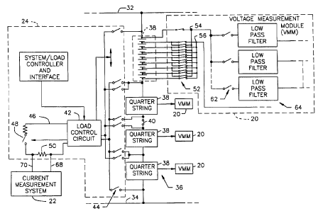
Figure 6 illustrates the data acquisition portion of
the system shown in Figure 5, coupled to one string of
the battery bank 14. As is conventional, within the
battery bank 14 the battery strings are connected in
parallel between a first rail 32 and a second rail 34.
Only one string 36 is illustrated herein and, as shown,
the string 36 is divided into four serially connected
quarters 38, with each quarter being made up of eight
serially connected battery jars. It is understood that
the string need not be divided into equal quarters in
order to practice the present invention. In any event,
substantially centrally of each string may be a central
disconnect switch,40, which forms no part of the present
CA 02325378 2000-09-21
WO 99/51993 PCTNS99/06711
invention, but is utilized to remove the string from the
battery bank 14.
The system/load controller and interface 24 includes
a load control circuit 42 which has a controllable switch
5 bank 44 associated with each of the strings. The switch
bank 44 is controllable for selectively coupling the load
control circuit 42 across a selected quarter string 38.
The current load used for battery jar measurements is
generated within the current path 46, there being .a
10 controllable switch 48 by means of which the long and
short duration current pulses are generated. A sensing
resistor 50 is provided in the current path 46, across
which is connected the current measurement system 22.
Each voltage measurement module 20 includes a switch
bank 52 coupled between the individual jars within the
associated quarter string 38 and a pair of voltage
measurement tenainals 54, 56. The switch bank 52 is
controllable by the microprocessor 58 (Figure 7) within
the voltage measurement module 20 to selectively couple
the jars within the quarter string 38 one at a time
across the pair of voltage measurement terminals 54, 56.
The voltage measurement terminal 56 is connected directly
to the analog to digital converter 60. The other voltage
measurement terminal 54 is connected through the switches
62 to the low pass filters 64, then through the switches
66 to the analog to digital converter 60. When the
voltage measurement module 20 is activated and one of the
battery jars within the quarter string 38 is connected to
the voltage measurement terminals 54, 56, the switches 62
are all closed and the switches 66 are all open. During
a current load pulse, the switches 62 are opened one at
a time so that a time-related sequence of voltage
measurements are held in the low pass filters 64. The
timing of the opening of the switches 62 corresponds to
the times when measurements are taken. The switches 66
are then sequentially closed to transfer these voltage
CA 02325378 2000-09-21
WO 99/51993 PCT/US99/06711
11
measurements to the analog to digital converter.
Alternatively, a single low pass filter with a very long
time constant and one set of switches 62, 66 can be
utilized. However, the double layer capacitance cannot
be computed in this case.
As shown in Figure 8, the current measurement system
22 is similar to the voltage measurement module 20 in
that the leads 68, 70 which are connected across the
sensing resistor 50 are connected one directly to the
analog to digital converter 72 and one through the
switches 74, the low pass filters 76 and the switches 78.
The current measurement system 22 also includes a
microprocessor 80 which, among other things, controls the
switches 74, 78.
Each of the voltage measurement modules 20 and the
current measurement system 22 includes an input/output
circuit 82 coupled to the bus system 26 for receiving
instructions from the system/load controller and
interface 24 and for transmitting collected voltage
measurement data to the system/load controller and
interface 24. The system/load controller and interface
24 does preliminary processing of the data and transmits
the data to the remote personal computer 28 for final
processing and evaluation of battery condition. Thus,
the personal computer 28 utilizes the voltage and current
measurement data to calculate and/or display the ohmic
resistance, the charge transfer resistance and the double
layer capacitance for each of the jars, in the manner
previously described.
Thus, typically, in a large battery backup or
standby system the remote personal computer 28 initiates
the collection of voltage measurement data once a week
during an off hour. The system/load controller and
interface 24 sends signals over the bus system 26 to
cause a string of long and short duration current pulses
to be applied to each quarter string and to have the
CA 02325378 2000-09-21
WO 99/51993 PCT/US99/06711
12
voltage measurement module 20 associated with that
quarter string take voltage measurements from each jar
within that quarter string. During the data collection
from each jar, a stream of both long and short duration
current pulses are applied to the quarter string. All of
the voltage measurement data is collected by the
system/load controller and interface 24 and transmitted
to the remote personal computer 28 for processing.
The system/load controller includes an internal real
time clock and may also be programmed to autonomously
take ohmic resistance, charge transfer resistance, and
double layer capacitance measurements for each jar at
predetermined specific time intervals at predetermined
specific times. The acquired data in this case is
temporarily stored in the voltage measurement modules as
well as the system/load controller for future downloading
to the remote personal computer.
Accordingly, there has been disclosed an improved
method and system for evaluating the status of battery
jars in a battery backup or standby system. While an
exemplary embodiment of the present invention has been
disclosed herein, it will be appreciated by those skilled
in the art that various modifications and adaptations to
the disclosed embodiment may be made and it is intended
that this invention be limited only by the scope of the
appended claims.