Language selection

Search

Patent 2325483 Summary

Third-party information liability

Some of the information on this Web page has been provided by external sources. The Government of Canada is not responsible for the accuracy, reliability or currency of the information supplied by external sources. Users wishing to rely upon this information should consult directly with the source of the information. Content provided by external sources is not subject to official languages, privacy and accessibility requirements.

Claims and Abstract availability

Any discrepancies in the text and image of the Claims and Abstract are due to differing posting times. Text of the Claims and Abstract are posted:

  • At the time the application is open to public inspection;
  • At the time of issue of the patent (grant).
(12) Patent: (11) CA 2325483
(54) English Title: METHOD FOR REMOVING COARSE-GRAINED SOLIDS FROM A STATIONARY FLUIDIZED BED
(54) French Title: PROCEDE PERMETTANT DE SUPPRIMER DES SOLIDES DE GRANULOMETRIE RELATIVEMENT IMPORTANTE D'UN LIT FLUIDISE STATIONNAIRE
Status: Deemed expired
Bibliographic Data
(51) International Patent Classification (IPC):
  • B01J 8/00 (2006.01)
  • F27B 15/02 (2006.01)
(72) Inventors :
  • HIRSCH, MARTIN (Germany)
  • ORTH, ANDREAS (Germany)
  • WEBER, PETER (Germany)
(73) Owners :
  • METALLGESELLSCHAFT AG (Germany)
(71) Applicants :
  • METALLGESELLSCHAFT AG (Germany)
(74) Agent: ROBIC
(74) Associate agent:
(45) Issued: 2007-11-20
(86) PCT Filing Date: 1999-07-01
(87) Open to Public Inspection: 2000-01-20
Examination requested: 2004-04-14
Availability of licence: N/A
(25) Language of filing: English

Patent Cooperation Treaty (PCT): Yes
(86) PCT Filing Number: PCT/EP1999/004526
(87) International Publication Number: WO2000/002654
(85) National Entry: 2000-09-22

(30) Application Priority Data:
Application No. Country/Territory Date
198 30 697.0 Germany 1998-07-08

Abstracts

English Abstract


According to the invention, a fluidizing gas is introduced
upwards into the fluidized bed (3) through a valve grid (2),
said stationary fluidized bed (3) containing solids with different
grain sizes. A supply pipe (10) is disposed in the area of the
fluidized bed, the mouth of said pipe being located above the
valve grid (2) and its outlet (12) leading outwards from the
fluidized bed (3). Part of the solids located above the valve
grid (2) is blown into the supply pipe by a gas jet (13) which
is directed upwards and fed separately from the fluidizing gas
and pneumatically evacuated from the fluidized bed through the
supply pipe (10). Normally, the flow speed of the gas in the
supply pipe is at least two times higher than the speed of the
fluidizing gas in the fluidized bed.


French Abstract

Selon l'invention, on introduit un gaz de fluidification dans un lit fluidisé stationnaire (3) contenant des solides de différentes granulométries, et ce par le bas via une grille (2). La zone du lit fluidisé renferme un tuyau de transport (10) dont l'ouverture se situe au-dessus de la grille (2) et la sortie (12) permet l'évacuation à partir du lit fluidisé. Par un jet gazeux (13) ascensionnel, acheminé séparément du gaz de fluidisation, une partie des solides se trouvant au-dessus de la grille (2) est soufflée dans le tuyau et évacuée du lit fluidisé par voie pneumatique par ce tuyau (10). Normalement, la vitesse d'écoulement du gaz dans le tuyau est au moins les deux fois celle du gaz de fluidisation dans le lit fluidisé.

Claims

Note: Claims are shown in the official language in which they were submitted.


6

CLAIMS

1. A process of removing granular solids from a stationary fluidized bed
which contains solids of different grain sizes, wherein fluidizing gas is
introduced
into the fluidized bed from the bottom, distributed through a jet bank, where
a
conveying tube is disposed in the fluidized bed above the jet bank, in which
conveying tube a gas jet directed into the conveying tube pneumatically
carries
solids upwards through the conveying tube and out of the fluidized bed,
characterized in that the inlet opening (11, 11a, 11b) of the conveying tube
(10,
10a, 10b) is disposed 10 to 500 mm above the jet bank (2), that a vertical gas

line (13) is disposed at a distance below the inlet opening, the upper end of
said
gas line being disposed approximately at the level of the jet bank, that by a
gas
jet from the gas line (13) into the inlet opening of the conveying tube coarse-

grained solids are pneumatically discharged from the fluidized bed through the

conveying tube, the gas velocity in the conveying tube being at least twice as

high as that of the fluidizing gas in the fluidized bed, and that the solids
are
supplied upwards to a bend (15) of the conveying tube and then downwards to
an outlet (12).

2. The process as claimed in claim 1, characterized in that the solids
discharged from the fluidized bed through the conveying tube are introduced
into
a second fluidized bed.

Description

Note: Descriptions are shown in the official language in which they were submitted.


CA 02325483 2000-09-22
1

METHOD FOR REMOVING COARSE-GRAINED SOLIDS
FROM A STATIONARY FLUIDIZED BED


Description
This invention relates to a process of removing relatively
coarse-grained solids from a stationary fluidized bed, which
contains solids of different grain sizes, wherein fluidizing
gas is introduced into the fluidized bed from the bottom,
distributed through a jet bank.

Stationary fluidized beds of this kind are generally known.
They are characterized by a more or less precisely defined
bed surface, which moves for instance like a boiling liquid.
During an extended operation of the fluidized bed solids of a
relatively large grain size accumulate in the lower portion
of the bed above the jet bank, as they are not or hardly flu-
idized. This accumulation of coarse grain can be disturbing
in many cases, as it can for instance lead to different dwell
times of the solids in the fluidized bed and also to an over-
heating and sintering in the vicinity of the jet bank. The
withdrawal of this coarse grain under the influence of grav-
ity downwards through the jet bank or laterally through the


CA 02325483 2006-11-07

2
container wall :requires a considerable effort in terms of
equipment and control technology.

It is the object underlying the invention to be able to at
least partly and easily remove the relatively coarse-grained
solids accumulating in the lower portion of a stationary flu-
idized bed. In accordance with the invention this is achieved
in the above-mentioned process in that by means of at least
one upwardly directed gas jet supplied separate from the flu-
idizing gas part of the solids disposed above the jet bank
are blown into a conveying tube, and these solids are pneu-
matically removed from the fluidized bed through the convey-
ing tube. Since the relatively coarse-grained solids accumu-
late directly above the jet bank, the same are, as far as
they are disposed in direct vicinity of the inlet opening of
the conveying tube, blown out of the fluidized bed through
the conveying tube together with the fine-grained solids pre-
sent near the inlet opening. The solids discharged in this
way can be separated into a coarse grain fraction and a fine
grain fraction by screening them outside the fluidized bed,
where for instance the fine grain fraction is directly recir-
culated to the fluidized bed and the coarse grain fraction is
first of all comminuted or subjected to a special treatment
in a second container.

More specifically, the invention is directed to a process of removing granular
solids from a stationary fluidized bed which contains solids of different
grain
sizes, wherein fluidizing gas is introduced into the fluidized bed from the
bottom,
distributed through a jet bank, where a conveying tube is disposed in the
fluidized bed above the jet bank, in which conveying tube a gas jet directed
into
the conveying tube pneumatically carries solids upwards through the conveying
tube and out of the fluidized bed, characterized in that the inlet opening of
the
conveying tube is disposed 10 to 500 mm above the jet bank, that a vertical
gas
line is disposed at a distance below the inlet opening, the upper end of said
gas


CA 02325483 2006-11-07

2a
line being disposed approximately at the level of the jet bank, that by a gas
jet
from the gas line into the inlet opening of the conveying tube coarse-grained
solids are pneumatically discharged from the fluidized bed through the
conveying tube, the gas velocity in the conveying tube being at least twice as
high as that of the fluidizing gas in the fluidized bed, and that the solids
are
supplied upwards to a bend of the conveying tube and then downwards to an
outlet.

The solids in the fluidized bed may have any temperature, the
spectrum of grain sizes may include grain sizes in the range
from 0.1 to 10 mm, but there are no absolute size limits for
this method.

The gas velocities of the fluidizing gas usually lie in the
range from 0.1 to 1 m/sec, where these figures are measured
as empty-tube velocities, here and later on. One or several
gas jets are upwardly directed from the bottom against the
inlet opening of the conveying tube, they entrain the solids
and guide them through the conveying tube, through which they


CA 02325483 2000-09-22
- 3 -

leave the fluidized bed. The gas velocities in the conveying
tube usually are at least twice as high as the velocity of
the fluidizing gas in the fluidized bed. Usually, the gas ve-
locities in the conveying tube are twice to five times as
high as in the fluidized bed.

It may be sufficient to install in the fluidized bed a single
conveying tube with at least one associated gas jet coming
from the bottom, but there may very well also be provided a
plurality of conveying tubes at different points in the flu-
idized bed, to each of which at least one gas jet is associ-
ated.

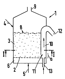
Embodiments of the method will be explained with reference to
the drawing, wherein:

Fig. 1 shows a vertical section along line II-II of Fig. 2
through a fluidized-bed reactor in a schematic repre-
sentation,

Fig. 2 shows a horizontal section along line I-I through the
reactor illustrated in Fig. 1, and

Fig. 3 shows a vertical section through a fluidized-bed re-
actor with two conveying tubes.

The reactor 1 illustrated in Figs. 1 and 2 has a stationary
fluidized bed 3 above a jet bank 2. Solids of different grain
sizes are charged into the reactor through line 4, and fluid-
izing gas is supplied through line 5. The fluidizing gas
first of all enters a distribution chamber 6, before it flows
through the jet bank 2 into the fluidized bed 3. The fluid-
ized bed has a solid surface 8, through which the gas escapes
in upward direction, where a certain amount of the fine-
grained solids is entrained. The gas leaves the reactor


CA 02325483 2000-09-22
- 4 -

through the outlet 9, and is supplied for instance to a de-
dusting not represented here.

At the wall of the reactor 1, see Figs. 1 and 2, a conveying
tube 10 is provided, which has an inlet opening 11 and an
outlet 12. The inlet opening 11 lies above the jet bank 2 by
the vertical distance (a), where (a) usually is 10 to 500 mm.
Below the conveying tube 10 and also directly below the jet
bank 2 a vertical gas line 13 is provided, through which in a
manner not represented here a gas jet is blown from the bot-
tom upwards through the inlet opening 11 into the conveying
tube 10. The upper end of the line 13 is disposed approxi-
mately at the level of the jet bank 2, so that solids from
the fluidized bed 3 constantly flow into the range of influ-
ence of the gas jet, which carries the same into the convey-
ing tube 10 and to the outlet 12. It may be expedient to sup-
ply the solids coming through the outlet 12, which are rela-
tively coarse-grained, to a comminution or to a not repre-
sented second fluidized bed. The fine grain contained in the
solids may first be screened out.

The number of the conveying tubes installed in the fluidized
bed of a reactor may be chosen as desired. In Fig. 3, two
conveying tubes l0a and lOb are represented, to which gas
lines 13a and 13b, respectively, are associated. The convey-
ing tube l0a is slightly inclined towards the top, and it
protrudes beyond the surface 8 of the fluidized bed. On the
other hand, the upper bend 15 of the conveying tube lOb lies
in the fluidized bed 3 slightly below its surface 8. The in-
let openings lla and lib of the two conveying tubes shown in
Fig. 3 are slightly flared towards the bottom, but this is
not absolutely necessary. The remaining reference numerals of
Fig. 3 have the meaning explained already in conjunction with
Figs. 1 and 2.


CA 02325483 2000-09-22
- 5 -
Example:

Into a continuously operated fluidized bed reactor, which is
designed in accordance with Figs. 1 and 2, 1125 kg/h quartz
sand are charged. 90 wt-% of the sand have a grain size of
0.1 to 0.4 mm, 10 wt-% of the sand have a grain size of 0.5
to 2.2 mm. The jet bank 2 has a surface area of 4.2 m2, the
height of the bed is 0.6 m. For fluidizing purposes air is
used, whose empty-tube velocity in the vicinity of the bed is
0.2 m/s. In the vicinity of the orifice 11, the air supplied
to the conveying tube 10 through line 13 has an empty-tube
velocity of 0.6 m/s. The conveying tube has a cross-sectional
area of 166 cm2, its distance (a) from the jet bank is 100
mm.

During an operation of 4 hours, the sand blown out through
the conveying tube is collected in a container. The total
amount of this sand is 270 kg, of which 180 kg (= 66.7 wt-%)
have a grain size of 0.5 - 2.2 mm, so that preferably coarse-
grained solids have been discharged.

Representative Drawing
A single figure which represents the drawing illustrating the invention.
Administrative Status

For a clearer understanding of the status of the application/patent presented on this page, the site Disclaimer , as well as the definitions for Patent , Administrative Status , Maintenance Fee  and Payment History  should be consulted.

Administrative Status

Title Date
Forecasted Issue Date 2007-11-20
(86) PCT Filing Date 1999-07-01
(87) PCT Publication Date 2000-01-20
(85) National Entry 2000-09-22
Examination Requested 2004-04-14
(45) Issued 2007-11-20
Deemed Expired 2012-07-03

Abandonment History

There is no abandonment history.

Payment History

Fee Type Anniversary Year Due Date Amount Paid Paid Date
Registration of a document - section 124 $100.00 2000-09-22
Application Fee $300.00 2000-09-22
Maintenance Fee - Application - New Act 2 2001-07-03 $100.00 2001-06-21
Maintenance Fee - Application - New Act 3 2002-07-02 $100.00 2002-06-26
Maintenance Fee - Application - New Act 4 2003-07-02 $100.00 2003-06-13
Request for Examination $800.00 2004-04-14
Maintenance Fee - Application - New Act 5 2004-07-01 $200.00 2004-06-16
Maintenance Fee - Application - New Act 6 2005-07-04 $200.00 2005-06-23
Maintenance Fee - Application - New Act 7 2006-07-04 $200.00 2006-06-21
Maintenance Fee - Application - New Act 8 2007-07-03 $200.00 2007-06-18
Final Fee $300.00 2007-08-31
Maintenance Fee - Patent - New Act 9 2008-07-02 $200.00 2008-06-17
Maintenance Fee - Patent - New Act 10 2009-07-02 $250.00 2009-06-22
Maintenance Fee - Patent - New Act 11 2010-07-02 $250.00 2010-06-17
Owners on Record

Note: Records showing the ownership history in alphabetical order.

Current Owners on Record
METALLGESELLSCHAFT AG
Past Owners on Record
HIRSCH, MARTIN
ORTH, ANDREAS
WEBER, PETER
Past Owners that do not appear in the "Owners on Record" listing will appear in other documentation within the application.
Documents

To view selected files, please enter reCAPTCHA code :


To view images, click a link in the Document Description column. To download the documents, select one or more checkboxes in the first column and then click the "Download Selected in PDF format (Zip Archive)" or the "Download Selected as Single PDF" button.

List of published and non-published patent-specific documents on the CPD .

If you have any difficulty accessing content, you can call the Client Service Centre at 1-866-997-1936 or send them an e-mail at CIPO Client Service Centre.


Document
Description 
Date
(yyyy-mm-dd) 
Number of pages   Size of Image (KB) 
Representative Drawing 2001-01-04 1 3
Abstract 2000-09-22 1 69
Claims 2000-09-22 1 39
Drawings 2000-09-22 1 14
Description 2000-09-22 5 194
Cover Page 2001-01-04 1 48
Description 2006-11-07 6 220
Claims 2006-11-07 1 33
Representative Drawing 2007-10-23 1 5
Cover Page 2007-10-23 1 40
Assignment 2000-09-22 6 174
PCT 2000-09-22 10 363
PCT 2000-09-23 4 134
Prosecution-Amendment 2004-04-14 1 30
Prosecution-Amendment 2006-06-21 2 33
Prosecution-Amendment 2006-11-07 6 189
Correspondence 2007-08-31 1 41
Correspondence 2011-08-15 1 77
Correspondence 2010-08-10 1 46