Note: Descriptions are shown in the official language in which they were submitted.
CA 02325947 2000-09-25
WO 99/50008 PCT/BE99/00041
THERMAL SHOCK-RESISTANT CERAMIC ARTICLE.
BACKGROUND OF THE INVENTION
Field of the Invention
This invention relates to a ceramic article and a method for the production of
the article, and
more particularly to an article and method comprising alternating layers of
dissimilar
materials to produce an article with an improved work of fracture.
Description of the Prior Art
Ceramic articles are, of course, well known and find many commercial uses
where, for
example, hardness, refractory properties or relative chemical inertness are
desired. A serious
deficiency of ceramic products, however, is their brittleness or, stated in
other words, their
poor work of fracture or toughness. This limitation has hindered the entry of
ceramics into
those areas where their other properties would be highly desirable, for
example, U.S. Pat. Nos.
5,657,729 and 5,687,787 describe attempts to incorporate toughened ceramic
parts into
internal combustion engines.
Brittle materials typically fail catastrophically and often without warning.
Conversely, tough
materials will normally bend or deform before failure. In most applications,
the latter type of
failure is preferred. Common methods of testing toughness are a Single Edge
Notch Bend
(SENB) test and a Modulus of Rupture (MOR) test. Both involve a three point
bending
geometry and differ in the presence or absence, respectively, of a notch in
the sample to be
tested. In both, a stress on a sample is slowly increased as a function of
strain. The resultant
area beneath a plot of stress versus strain is the work of fracture and
represents the amount
of energy absorbed during one of these tests.
A tougher material has the ability to absorb greater amounts of energy than a
more brittle
material. One way a material may absorb energy is by microscopic morphological
changes.
For example, tough metals or alloys like steel absorb energy by, for example,
developing
dislocations, slipping across crystal planes, or undergoing crystal twinning.
A material may
also absorb energy by creating new surface area through a process known as
crack blunfiing.
For example, composite materials, such as fibreglass, are heterogeneous and
contain a
plurality of phases. When a crack reaches a phase boundary, the crack may
propagate along
the boundary, and create a delamination crack. In effect, the crack is blunted
at the phase
boundary. Blunting reduces crack propagation by spreading the energy at the
crack tip over a
larger area.
GeneraIIy, ceramic materials cannot absorb much energy because their crystal
structure
resists microscopic morphological changes. Additionally, crack blunting does
not occur to any
substantial extent in homogeneous materials. Attempts to improve the toughness
of ceramics
have concentrated on introducing some degree of heterogeneity into the
ceramic. For example,
an increase in toughness has been accomplished by providing a second phase
within the
ceramic, such as a layer of fibers, see, e.g., U.S. Pat. No. 5,589,115.
Presumably, the fiber
layer disrupts crack propagation by blunting the crack tip. Unfortunately,
this solution is not
without its flaws. The green ceramic matrix, in which the fiber is placed,
shrinks when fired,
but the fiber itself does not. This results in delamination of the fiber from
the ceramic and
CA 02325947 2000-09-25
WO 99/50008 PCT/BE99/00041
2
creates what are essentially voids in the brittle ceramic. Voids normally act
to concentrate
stresses, initiate crack formation, and increase the likelihood of brittle
failure.
Techniques to overcome this problem involve a plurality of mats of ceramic
fibers impregnated
with a particulate ceramic material, liquid diluent and organic binder. This
technique places
the ceramic particulate in more intimate contact with the fiber. During
firing, however, the
ceramic particulate stt11 shrinks. While an improvement over the prior art,
this method does
not completely overcome the delamination problem, and results in a ceramic
composition with
variable mechanical properties.
Delamniation can be substantially overcome by a technique involving melt
infiltration. This
technique involves perfusing a molten ceramic material into cetamic fibers.
Although
delamination is reduced, several new problems arise. Very high temperatures
are required to
melt ceramics and some ceramics sublime before they melt. The high
temperatures can also
damage the ceramic fiber. Even if the ceramic can be melted, the viscosity of
a molten ceramic
is so high that the rate of infiltration into the fibers is very slow and the
molten ceramic may
not homogeneously wet the surface of the fibers.
The extremely high temperatures of melt infiltration can be avoided by a vapor
infiltration
technique, see, e.g., U.S. Pat. No. 5,488,017. At relatively low temperatures,
a vapor
comprising a ceramic precursor infiltrates ceramic fibers. Later the chemical
is decomposed to
leave a ceramic residue. For example, gaseous methyltrichlorosilane may be
deposited onto
ceramic fiber at just several hundred degrees centigrade and later decomposed
to silicon
carbide at a temperature which may be less than 1200oC. A silicon carbide
matrix is created
which is reinforced by the ceramic fiber. Although overcoming some of the
disadvantages of
previous processes, vapor infiltration is very time-consuming and limited to
ceramics with
volatile precursors.
U.S. Pat. No. 5,591,287 avoids using fibers, melts or volatile precursors.
This patent creates
one or more zones of weakness between layers of sinterable, particulate
ceramic material. The
zones of weakness consist of very thin layers of non-sinterable or weakly
sinterable material.
Examples of a non-sinterable material include carbon or an organic polymeric
material, which
may pyrolyze in.to carbon. A weakly sinterable materlal may form bonds with
itself and the
sinterable, particulate ceramics, but the bonds so formed should be
substantially weaker than
the bonds formed within and between the sinterable ceramic layers.
The zones of weakness should be less than about 50 microns to permit sintering
between
ceramic layers. Such thin zones of weakness may be created by spreading a
suspension of
non-sinterable or weakly sinterable material over one surface of a preformed,
sinterable
ceramic. Many zones of weakness may be produced by depositing the non-
sinterable material
between each of a plurality of ceramic layers. The result.ing zones of
weakness may deflect
cracks propagating through the ceramic. The crack may then travel along the
zone of
weakness and form a delamination crack between the layers of ceramic. The
process of
delamination increases the work of fracture. Unfortunately, this method is
li.mited to
sinterable ceramic materials that have been preformed into a layer over which
a non- sinterable
CA 02325947 2009-03-04
3
material can be spread. This restricts both the composition and the geometry
of articles,
which may be made using this method.
Despite these known methods for improving the toughness of ceramic articles,
there is still a
need in the industry for a method to produce quickly and cheaply a tough
morphology in a
commercially useful shape. Simply mixing a ceramic fiber into a sinterable
ceramic often
leads to delamination between the two materials. Methods to prevent
delaminations are either
too time-consuming, limit article geometry or composition, produce
inconsistent results, or
require excessive temperatures. A commercially viable method is needed to
toughen a ceramic
article.
SUMMARY OF THE INVENTION
The present invention relates to a multilayer ceramic article and a method of
making the
same. In a broad aspect, the article comprises a plurality of layers of a
first phase each
separated by a layer of a mechanically or chemically different second phase.
The article of the
present invention is depicted as possessing a substantially improved work of
fracture
compared to a ceramic article without a layered structure.
In another aspect, the article comprises
(a) at least one layer of a first phase comprising a fused ceramic, a
carbon bonded particulate ceramic or a mixture of these ceramics; and
(b) a layer of a mechanically or chemically different second phase
embedded or encapsulated therein.
The first phase is described as a fused or carbon-bonded, particulate ceramic.
The second
phase may be a porous material, such as a metal mesh, or a weakly fused or
carbon-bonded
refractory, or may even comprise the pyrolyzed residue of a combustible
material.
Alternatively, the second phase may be fused by a process independent of the
first phase, such
as by sintering if the first phase is a carbon-bonded ceramic. Ln other
embodiments, the
second phase may share a similar bonding mechanism with the first phase but
will possess
signiftcantly weaker mechanical properties.
The invention describes layers of the first phase as preferentially having a
thickness from
between about 0.5 mm to about 10 mm with layers of the second phase having a
thickness
from about 0.005 mm to about 2 mm.
One aspect of the invention describes the layers as spiralling along the
longitudinal axis of a
cylindrical shape. The article may also comprise a bore.
The present invention also relates to a method for producing a ceramic article
having improved
thermal shock- resistance and toughness. In a broad aspect, the invention
describes a
CA 02325947 2009-03-04
3a
method to fashion a ceramic article by alternating layers of a first material
with a second
material. The first material may be a fusible or carbon-bonded, particulate
ceramic. The
second material is expected to form a weakly fused or weakly carbon-bonded
layer.
Alternatively, the second material may fuse by way of a process independent of
the first
material, such as by sintering if the first material is a carbon-bonded
ceramic. The second
material may be proffered as a sheet, film, membrane, or even a casing onto or
into which the
first material may be placed. The layers are then pressed into a piece and
fired to form the
finished article.
More specifically, the invention as claimed relates to a method for producing
a
multilayer ceramic article, comprising:
(a) laying down a sheet having a thickness between about 0.005 mm and
about 2.0 mm;
(b) depositing onto the sheet a layer of a fusible, particulate ceramic
composition at a thickness between about 0.05 mm and about 20 mm;
(c) depositing at least one further layer;
(d) pressing a plurality of layers to form a piece; and
(e) firing the piece at a temperature sufficient to fuse the ceramic
composition.
The invention as claimed also relates to a method for producing a multilayer
ceramic article, comprising:
(a) filling a plurality of sleeves each with a fusible, particulate ceramic
composition;
(b) layering said plurality of sleeves;
(c) pressing the plurality of layered sleeves to form a piece; and
(d) firing the piece at a temperature sufficient to fuse the ceramic
composition.
In one aspect of the invention, the second material is described as a
combustible material,
which may pyrolyze at elevated temperatures. The combustible material may be
an organic
CA 02325947 2000-09-25
- WO 99/50008 PCT/BE99/00041
4
material, such as plastic, paper, cotton or other natural or synthetic
polymer.
Still another aspect of the invention describes a process to make a layered,
cylindricat article.
The first material is described as a ceramic refractory and the second
material may be a
combustible sheet. Layers are alternated by coating the combustible sheet with
the ceramic,
compacting the ceramic on the sheet, and subsequently rolling the coated sheet
onto itself
thereby creating a cylinder with a "jelly roll" morphology. The second
material may
alternatively be a tubular casing. The ceramic material may then be inserted
into the casing,
compacted, and formed into any desired shape, including a"jelly roll."
A still further aspect of the invention describes a method of making the
article into a tube by
wrapping a coated sheet or $lled casing around a mandrel, pressing the wrapped
sheet or
casing on the mandrel, removing the piece from the mandrel, whereby a bore is
created where
the mandrel had been, and firing the wrapped sheet or casing to make the
article.
Other details, objects and advantages of the invention will become apparent as
the following
description of a present preferred method of practising the invention
proceeds.
DESCRIPTION OF THE DRAWINGS
FIG. 1 is a drawing of an article having the alternating layered structure of
the invention.
FIG. 2 depicts a method for creating the article of FIG. 1 using an organic
sheet.
FIG. 3 shows a method for creating the article of FIG. 1 using an organic
casu~g.
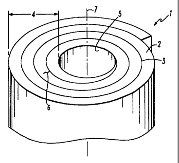
In Figure 1, an article fashioned into a tube by the method of the invention
is shown. The
tube 1 comprises a plurality of alternating layers of a first phase 2 and a
second phase 3. The
total number of layers depends upon the thickness of each layer and the
desired thickness 4
of the tube 1. Both the first phase 2 and the second phase 3 spiral outward
from a bore 5
within the tube 1. Such a geometry inhibits a crack 6 from propagating
perpendicularly to the
lon~itudinal axis 7 of the tube 1.
In Figure 2, a method of making a tubular ceramic article is illustrated. An
organic sheet 10,
which is comprised of a second material, is unwound from a take-off roll 11. A
first material
12 is deposited on the sheet 10, and the sheet 10 is wound on a mandrel 13 to
form a tube 14
having a plurality of layers until the desired thickness 15 is achieved.
In Figure 3, an alternate method involving a casing 20, which comprises a
second material is
depicted. A first materia121 is feed into a hopper 22 and forced into the
casing 20. The filled
casing 20 is compacted between rollers 23 and wound up on a mandre124 to form
a tube 25.
DESCRIPTION OF THE PREFERRED EMBODIMENT
The present invention describes a ceramic article, which has improved thermal
shock-
resistance and toughness, and a method of producing the same. The article is
especially
useful in the continuous casting of molten metals, and may be manufactured so
that different
ceramic compositions are exposed to the molten metal stream, slag line, and
mould area. The
method comprises depositing and compacting a first material onto or into a
second material.
The substrate may then be shaped, pressed, and fired into a ceramic article.
CA 02325947 2000-09-25
WO 99/50008 PCTBE99/00041
The article comprises a plurality of layers comprising at least two phases.
Adjoining layers of
a first phase are in physical contact with each other, and between layers is
an interface. The
interface comprises an area of reduced contact between adjacent layers of a
first phase,
whereby a propagating crack may preferentially follow the interface and
effectively blunt the
5 crack. Crack blunting increases the energy absorbed by the article, as
measured by work of
fracture, and improves the article's toughness.
The first phase may comprise any type of fusible or carbon-bonded, particulate
ceramic. For
convenience, "fused" or "fusible" is meant to include those ceramics, which
may be "sintered"
or "carbon-bonded". A particulate ceramic comprises any type of ceramic
whether powdered,
granular, fibrous, chunked, or any shape or combination of shapes, and of
whatever size,
which are amenable to being pressed into a form. Fusible implies a ceramic
which may be
fired to create a fused article out of a collection of ceramic particles. A
binder is often used to
hold together a fusible ceramic before firing. The ceramic is ultimately fired
at a temperature
high enough to coalesce the ceramic particles, thereby creating a fused mass.
A certain
amount of void fraction may remain because the ceramic particles do not
completely fuse or
lose their individuai identity. In contrast, a non-fusible ceramic may sublime
or degrade
before fusion occurs, or the selected firing temperature may simply be too low
to trigger fusion.
The fusible, particulate ceramic may be selected from any number of commonly
known
ceramic compounds, and will usually, at least in commercial applications,
comprise a mixture
of ceramic compounds. The actual mixture chosen wi11 depend upon the
particular
application in which the ceramic article will be used. For example, ceramic
compositions,
which are used in handling molten metals may comprise alumina, silica, silicon
carbide,
zirconia, and other refractory ceramic compounds. A typical refractory ceramic
mixture used
in stopper rods for steel processing may comprise major amounts of alumina and
graphite
with minor amounts of silica and other refractory ceramics. Graphite, a non-
ceramic
particulate material, is commonly added to improve thermal shock-resistance.
Alternatively, a
specialised refractory having excellent corrosion and erosion resistance, but
poor thermal
shock- resistance, may comprise a major amount of alumina with minor amounts
of zirconia
and silica
The invention also creates the possibility of using new ceramic compositions,
which take
advantage of the improved tougtniess of a layered morphology. For example,
ceramic
compositions may be used that previously had been too brittle or thermal shock-
sensitive but
possessed otherwise desirable properties. Ingredients, which had been
necessary for certain
physical properties, may be reduced or eliminated. In particular, graphite,
which improves
thermal shock-resistance, undergoes deleterious oxidation. A layered
morphology may enable
the use of less graphite, resulting in a product less sensitive to oxidative
degradation.
The invention is not limited to using only a single ceramic mixture or
composition within any
one article. In fact, it is contemplated that a plurality of ceramic
compositions wi11 be used in
any finished article. This may be particularly advantageous when different
properties are
desired at different places of the finished article. For example, in sub-entry
shrouds for the
CA 02325947 2000-09-25
WO 99/50008 PCTBE99/00041
6
continuous casting of molten metals, a first ceramic composition having good
slag resistance
may occupy an outer layer of the shroud, a middle layer may comprise a ceramic
composition
having good thermal shock-resistance, and an inner composition may comprise a
good
erosion-resistant ceramic.
Along with a first phase comprising a ceramic material, the article also has a
second phase.
The second phase separates and may sandwich layers of the first phase. The
second phase
may comprise, for example, carbon fibers, a metallic mesh, a pyrolyzed
residue, a relatively
weakly fused ceramic, or a ceramic fused by mechanism different than the
mechanism of the
first phase. In ail cases, the second phase is intended to interfere with
inter-layer fusion of
adjacent layers of first phase. Such interference creates an interface which
is weaker than the
first phase. The interface is characterized as a region comprising relatively
few bonds between
adjacent layers or as a discontinuity in the article's microstructure. The
second phase may be
introduced as a powder, slurry or suspension but, preferably, the second phase
begins as a
substrate capable of supporting or containing the ceramic particulate. Most
commonly, the
substrate will be a sheet or casing. The term "sheetn is meant to include any
fiim, textile,
cloth, or any other like substance characterized by two of its dimensions
greatly exceeding its
third. "Casing'' is meant to include any flexible sheath, jacket, tube, sleeve
or similar article,
which may be formed by connecting opposing edges of a sheet, and into which
the ceramic
particulate may be placed.
A sheet or casing wflI most commonly be an organic material, such as a
synthetic or natural
polymer, but may also include a mesh made from an inorganic material.
Inorganic materials
include metal or inorganic fibers such as graphite or ceramic fiber. Synthetic
polymers
include, for example, polyolefins or polyesters, but may include any type of
synthetic polymer
that may be fabricated into sheet or casing. Natural polymers include, for
example, paper or
cotton, but other natural polymers may also be used.
A sheet is preferably a paper product, owing mostly to paper's low cost, good
mechanical
strength, and low stretching under tension. The sheet is likely to experience
tension during
processing, and many common synthetic polymers stretch unacceptably. The
thiclmess of the
sheet is roughly dependent on the thickness of the ceramic layer. A thicker
sheet is preferred
to support a thicker ceramic layer. The sheet wi11 generally be thinner than
the ceramic layer
and often wiill be about one-tenth the thickness of the ceramic layer. It is
appreciated,
however, that the invention incorporates a range of thicknesses at least
between about 0.005
mm to about 2.0 mm, irrespective of the thickness of the ceramic layer.
Typically, the sheet, especially organic sheets containing oxygen as part of
their chemical
composition, will pyrolyze at temperatures needed to fuse the ceramic
material. Pyrolysis may
leave a trace residue between adjacent ceramic layers, but may also leave a
defect, which is
weaker than the rest of the fused article. The defect may be described as a
weakly fused
regiion relative to the fusion found in the ceramic layers. A crack
propagating within a ceramic
layer may impact this region and deflect along the defect thereby forming a
delamination
crack. The energy needed to produce the delamination increases the work of
fracture and,
CA 02325947 2000-09-25
- WO 99/50008 PCTBE99/00041
7
correspondingly, the toughness of the ceramic article.
The combustible sheet will preferably have holes. The holes should permit
adjacent layers of
the ceramic particulate to contact each other through the holes in the sheet.
Upon firing of
the article, contact between the ceramic layers through the holes may permit
some fusion
between layers. The combustible sheet is expected to pyrolyze at firing
temperatures but not
before preventing substantial contact and, therefore, fusion in the region
between ceramic
layers. The region, which had been occupied by the now pyrolyzed sheet, may
after firing
contain a weakly fused defect in the ceramic article.
It will be understood that, even in the absence of holes in the combustible
sheet, some fusion
may occur between ceramic layers. Holes, however, may permit the sheet to be
thicker and,
consequently, stronger and easier to handle than sheets without holes. Weakly
fused defects
may be produced by sheets without holes, but these sheets may need to be
thinner than
corresponding porous sheets. A thinner sheet could lead to manufacturing
difficulties when
producing a ceramic article according to the method of this invention. Thinner
sheets are
expected to flex more and support less ceramic particulate before buckling.
A sheet without holes or a sheet of excessive thickness may even create
defects in the ceramic
article that actually decrease toughness. These defects may result from little
if any fusion
between ceramic layers after the combustible sheet has pyrolyzed. A crack
propagating
through a ceramic may encounter a defect, which had been created between
ceramic layers by
pyrolysis of a combustible layer. The crack may deflect along the plane of the
defect. Without
some fusion between the ceramic layers, the crack will propagate rapidly along
the plane of the
defect because no additional energy wflI be needed, for example, to break
bonds formed by
fusion. Toughness will generally not be improved by this type of defect
because, as previously
taught, greater toughness correlates with greater energy input. Cracking
without the need for
energy input would not be expected to improve toughness.
A competition exists, therefore, between maximising and minimising the degree
of fusion
between ceramic layers. Less fusion between ceramic layers creates a more
"perfect" defect,
and may increase the chance that a crack propagating through the ceramic will
deflect along
the plane of the defect. Once the crack has deflected along the defect,
however, it may then be
desirable to have as many points of fusion as possible because more energy
would be needed
to break the bonds. But, the greater the degree of fusion between ceramic
layers, the more
the defect begins to look like the ceramic matrix and the less chance the
crack will deflect
along the defect. The number, shape, and size of holes, as well as the sheet
thickness, will
affect the degree of fusion in the article; therefore, the combustible sheet
should be selected
with this balance in mind.
The combustible sheet will preferably be a porous paper with a thickness about
0.005 mm to
about 0.5 mm. A porous paper is a paper which permits layers of fusible,
particulate ceramics
on either side of the paper to contact one another intermittently. Porous
paper may include
those papers having holes, which are ssmilar to or larger than the size of the
ceramic
particulate. Such holes may, for example, be defined by spaces between
cellulose fibers
CA 02325947 2000-09-25
- WO 99/50008 PCTBE99/00041
8
making up the paper. The holes may also be created by mechanical means, such
as by
perforating the paper. Paper possesses a substantial amount of rigidity and
strength, which
is needed to support the ceramic material in the method of the invention. At
the same time,
the paper may be made thin enough to permit intermittent contact between
ceramic layers on
either side of the paper. Paper also has a relatively low flash point and
leaves minimal
pyrolyzed residue.
The combustible sheet may also be a polymer fiim, such as polypropylene,
polyethylene or any
flexible organic polymer sheet. Plastic films normally will be contiguous and
free of pinhole
defects. This property may inhibit fusion between ceramic layers; although,
holes may be
made in the plastic to improve fusion between ceramic layers. Polymer films
disadvantageously may stretch when under tension, as may be experienced by the
film during
processing.
Holes in a combustible sheet permit the sheet to be substantially thicker than
without holes.
For example, porous paper sheets over 1.0 mm thick may still permit adjacent
ceramic layers
to contact one another and feLw together when fired. Handling includes all
those processes
concerned with the sheet itself, for example, rolling or unrolling the sheet,
and also a11 those
processes related to the sheet in combination with the ceramic. By comparison,
nonporous
sheets should be substantially thinner to achieve some fusion between ceramic
layers. As a
sheet becomes thinner, the sheet becomes increasingly flexible and subject to
stretching.
These properties make the sheet more difficult to handle.
Mechanical properties of the sheet are important because the invention
utilises the sheet as a
support in the process. In one embodiment, the ceramic article is cylindrical
as, for example,
a nozzle, pouring tube or stopper rod to be used in molten metal processing. A
combustible
organic sheet is unwound from a take-o$'roll and transported horizontally
towards a take-up
roll. Between the two rolls, the sheet is covered with a fusible, particulate
ceramic to a
thickness between about 0.5 mm and about 10 mm. During the process, the
composition and
thickness of the ceramic layer may be changed one or more times. The sheet
wfll have a
thickness equal to at least about one-tenth the thickness of the ceramic
layer. Thinner sheets
may also be used if the sheets' mechanical strength is suffscient. Thicker
sheets may also be
used if desirable. Preferably, the sheet has a thickness between about 0.05 mm
and 1.0 mm.
After being deposited on the sheet, the ceramic material is then compacted to
increase the
density of the ceramic layer. The ceramic layer should be compacted enough to
permit easy
handling but should still be flexible enough to be bent without cracking. The
sheet with the
compacted, fusible ceramic is wound up on the take-up roll. When the desired
thickness on
the take-up roll is achieved, the take-up roll is removed. Material on the
take-up roll may
comprise the ceramic article or the material may be rewrapped into another
shape or around
another ceramic piece. In this fashion, spirals of layers of sheet and ceramic
material are
deposited within the ceramic article.
Rewrapping the compacted ceramic/sheet permits a second compacted
ceramic/sheet to be
co-wrapped with the first. In this fashion, two substantially different
ceramic compositions
CA 02325947 2000-09-25
WO 99/50008 PCT/BE99/00041
9
may be intimately fused to form the finished article. For example, a good
thermal shock-
resistant ceramic may be layered with a good erosion-resistant ceramic in
altemating layers.
The finished article may gain the benefits of good thermal shock-resistance
and good erosion-
resistance. In a like fashion, a third, fourth or more ceramic compositions
may be co-wrapped
to achieve optimal properties.
After being formed into its final shape, the wrapped roll is pressed into a
piece. Pressing can
utilise any number of known processes, for example, as is common in three
dimensional
objects, isostatic pressing may be used. The piece is then fired at a
temperature necessary for
fusion. Of course, firing temperature depends on the ceramic composition.
Firing
temperature may also depend on several other factors, such as firing time and
desired porosity
in the finished article. Such parameters are well known by those skilled in
the art. After
firing, the finished ceramic article results.
Although an article of this invention may be produced using sheet, the
preferred method of
producing the disclosed article comprises placing a ceramic particulate into a
casing and
compacting the fiIIed casing. Techniques used in the sheet process may also be
applied when
using a casing. Unlike compacting on a sheet, the compacted casing presents an
easy way to
manipulate the ceramic particulate because the ceramic particulate is
completely contained
witbin the casing. By comparison, compacted ceramic on the surface of a sheet
could fall
from the sheet if turned upside down or even sideways. Filling the casing with
ceramic
particulate normally involves a technique similar to sausage making, in that
the ceramic is
placed into a hopper and forced into a casing. The filled casing is compacted,
and the
compacted casing may be manipulated in any manner to fashion an article.
Conveniently, the
casing is compacted between a pair of rollers, but a single roll may be
preferred in certain
circumstances. Naturally, the type of ceramic particulate being fed into the
casing at any one
time may vary depending on the type of article being made and the properties
required. For
example, a thermal shock-resistant ceramic may be used at one stage of casing
fylling, while a
more erosion-resistant composition may be used during a later stage. Several
casings having
different ceramic compositions may even be co-wrapped or copressed and fired
into the
finished article.
As described, the casing may be any type of tubular material such as paper or
synthetic
tubing, but in practice, the preferred material wilt be a cotton gauze. Cotton
gauze is
inexpensive, readily available, pyrolyzable, and is compriaed of a very open
weave containing
many holes. The gauze may be placed under tension to completely open the
weave. The
gauze may also be impregnated with binder, graphite, or any other substance
shown
beneficial to the process. It is useful to note that, unlike sheet-produced
articles, an article
produced by winding up a compressed casing will have a morphology
characterized by a layer
of ceramic followed by two layers of the casing. Practically, the two distinct
layers may be
considered as one. The compacted casing may be likened to a sheet; therefore,
it is
anticipated that a second or even third layer of ceramic particulate may be
placed on the outer
surfaces of the compacted casing. In either embodiment, the layers within a
finished article
CA 02325947 2000-09-25
wO 99/50008 PCT/BE99/00041
may be other than strict alternating layers of ceramic/substrate expected in a
sheet-produced
article.
Whether using the sheet or casing process, the ceramic article produced will
commonly be
cylindrical, and may also comprise a bore. Nozzles and pouring tubes will
naturally contain a
5 bore. A bore may be easily fashioned in the finished article by winding the
coated sheet or
filled casing around a mandrel. Pressing and firing will then create a ceramic
a.rkicle with a
bore. Layers comprising the first and second materials will spiral outwardly
from and around
the bore; although, this spiral need not be concentric and may even be
interrupted by other
components within the article or by the required shape of the finished
article.
10 The process is not limited to the creation of cylindrical articles. Various
other shapes may
also be formed. In articles produced using sheet, the sheet should be at least
about 0.005
mm to about 0.5 mm; although, thinner or thicker sheets may be used depending
on
processing conditions. Additionally, the ceramic is not necessarily compacted
before pressing.
For example, a method to produce a simple board product may comprise laying
down a sheet,
placing a particulate, fusible ceramic material on the sheet, laying down a
second sheet and a
second layer of ceramic material, and continuing to alternate layers until the
desired
thickness is achieved. Such a process is also useful in manufacturing slide
gate plates. The
entire article may then be pressed and fired to form the multilayer article.
Manufacturing
using the casing method may be even more versatile than manufacturing with
sheet material.
The casing holds the ceramic in place and, consequently, may be positioned
with greater
efficacy.
The layered article may be embedded or even fully encapsulated in a non-
layered object. This
may be especially useful to arrest cracking at particular points of a
commercial product. For
example, a sub-entry shroud used in the continuous casting of steel will
experience extreme
thermal stress, chemical assault and erosion at the slag line. Inclusion of a
layered article
within the shroud at the slag line may effectively arrest cracks and permit
the use of more
erosion-resistant ceramics.
Exam le
A quantity of porous paper of thickness 0.05 mm was
removed from a roll of paper. The paper was cut to a predetermined length and
flattened. A
standard mix of a fusible, particulate ceramic composition was deposited onto
the paper. The
mix comprised 50-55 weight percent alumina, 13-17 weight percent silica, and
30-35 weight
percent graphite. The composition was selected as representative of the type
of ceramic mix
used in nozzles for the continuous casting of molten steel. The ceramic mix on
the paper was
compacted to a thickness of 1.0 mm, and the coated paper was then continuously
wrapped
around a steel mandrel until a desired thickness was achieved. The coated
paper on the
mandrel was isostatically pressed to compact the ceramic particles, thereby
forming a piece.
The piece was fired at a temperature of up to 1000OC in a reducing atmosphere
to form a
ceramic article. The ceramic article was cut into test samples for Modulus of
Rupture (MOR)
tests. A comparative, non-layered standard was created consisting of the
ceramic mix without
CA 02325947 2000-09-25
- WO 99/50008 PCTBE99/00041
11
the paper sheet. The same ceramic composition, pressing and firing conditions
were used as
for the layered piece. Ten samples of the non-layered piece were also cut for
MOR tests. The
multilayer piece had an average work of fracture equal to 177,000 erg/cm2
compared to the
standard piece that had an average work of fracture of only 42,000 ergs/cm2.
Example II
A tubular article of the present invention was made by feeding a particulate
ceramic mix into
a first open end of a hopper. The same ceramic composition was used as in the
preceding
example. A medical grade cotton gauze sleeve was placed over a second open end
of the
hopper. The ceramic was extruded from the hopper into the cotton sleeve. The
sleeve was
drawn between two rollers whereby the ceramic mix inside the sleeve was
compacted. The
compacted sleeve was wrapped around a mandrel and shaped into a cylinder. The
wrapped
sleeve was isostatically pressed at up to 140 MPa (20,000 psi) and fired below
1000 C in a
reducing atmosphere.
Example III
Particulate alumina-graphite was compressed inside a cotton gauze sleeve and
formed into an
annular ring having twelve layers of alumina-graphite. Each layer was less
than 5 mm thick.
A sub-entry shroud was created with the annular ring at the slag line and
completely
encapsulated by the body of the shroud. The shroud was placed into molten
steel at 2900OF
to the level of the annular ring. After reaching temperature, the shroud was
removed and
sprayed with water to simulate extreme thermal shock conditions. The exterior
of the shroud
cracked at the level of the annular ring. After sawing the shroud
longitudinally, the crack was
clearly seen to begin at the exterior of the shroud and to stop at the multi-
layer annular ring.
In a similar shroud without the annular ring, the crack extended completely
through the
shroud. The annular ring, which was made from a layered material, was deemed
capable of
blunting the advancing crack tip.