Note: Descriptions are shown in the official language in which they were submitted.
CA 02326200 2000-09-27
WO 99/52444 PCT/US99/07728
DISPOSABLE ANESTHESIA DELIVERY SYSTEM
Background of the Invention
The present invention relates to a disposable delivery
system for delivering anesthesia. In particular, the present
invention relates to a disposable delivery apparatus and
method for intraosseously delivering dental anesthesia or
anesthesia to other parts of a living body.
The present invention is described in detail below with
respect to application of dental anesthesia, but the invention
is applicable to delivery of anesthesia or other fluids to
other parts of a living body, either human or animal. In
particular, the present invention is applicable to other
surgical procedures such as, for example, orthopedic surgical
procedures. Thus, although the invention is described in
detail with respect to delivery of dental anesthesia, the
invention is not intended to be limited to use only in
connection with dental procedures.
In general, anesthesia is delivered by injection of a
topical anesthetic followed by a deeper injection of
anesthetic for desensitizing nerve endings within the region
of interest (infiltration) or for blocking off remote sensory
nerves which are coupled to the region of interest (nerve
blocking).
It is extremely desirable to minimize the amount of
anesthesia injected because toxic reactions may result from
drug sensitivity or misdirection of the injection needle into
- 1 -
CA 02326200 2000-09-27
WO 99/52444 PCT/US99/07728
the bloodstream. Such risk of toxic reaction is heightened
when repeated administration of anesthesia as required, as is
often the case with conventional delivery techniques. In
addition, conventional administration of dental anesthesia
generally results in numbness of the tongue, cheek, lips
and/or even part of the face of the patient for some time
after a procedure.
As set forth in USP 4,944,677 to Alexandre, conventional
methods of delivering dental anesthesia include injection into
mucous tissue, injection into a ligament, injection into the
septum and injection near a nerve-trunk. However, injection
into mucous tissue is disadvantageous because it takes a long
time for the anesthesia to take effect (about 5 minutes),
because the amount of anesthesia is high (about 4 cc), and
because adrenalin or another vaso conductor is required for
cardiac patients. Injection into a ligament is
disadvantageous because it requires high pressure for
injection (which causes pain), because injection is into a
septic area, because the risk of infection of the ligament is
increased, and because the risk of post-operative problems
including inflammation and necrosis is increased. Injection
into the septum is disadvantageous because it also requires
high pressure for injection (which causes pain), because exact
positioning of the needle is required, and because injection
is into a septic area. And finally, injection near the nerve-
trunk is disadvantageous because there is a long delay in
effecting anesthesia (about 10 minutes), because there is a
high risk of inadvertent injection into a blood vessel, and
because post-operative numbness is very long lasting.
30- Intraosseous delivery of dental anesthesia directly into
the jawbone is also known. Intraosseous delivery is extremely
advantageous because it very rapidly achieves numbness limited
only to the tooth to be treated, because it enables the amount
- 2 -
CA 02326200 2000-09-27
WO 99/52444 PCT/US99/07728
of anesthetic to be significantly reduced, and because post-
operative numbness is essentially avoided.
USP 1,539,637 to Bronner discloses a dental instrument
adapted for use in penetrating bone structures in order to
provide drainage or to inject anesthetics or other fluids.
The dental instrument of Bronner essentially comprises a chuck
to which a hollow drill may be connected. The dental
instrument includes a slidable cleaning pin for preventing
cuttings from entering a passage in the hollow drill during
bone penetration. Once the hollow drill has penetrated the
bone, a syringe is coupled to the dental instrument in order
to inject fluid such as an anesthetic. The pressure of the
injected fluid causes the cleaning pin to be withdrawn from
the interior of the hollow drill to thereby permit the flow of
fluid through the passage in the hollow drill into the
interior of the bone. The dental instrument of Bronner,
however, is cumbersome and cannot remain in place during the
performance of a dental procedure, and also does not enable
simple re-injection of anesthetic, if and when required,
during the performance of a dental procedure.
USP 2,317,648 to Siqveland discloses an intraosseous
delivery apparatus and method whereby a threaded sleeve is
concentrically and removably positioned around a drill bit.
The drill bit and threaded sleeve are used together to
penetrate the bone, and then the drill bit is detached and
withdrawn, leaving the threaded sleeve embedded in the bone as
a guide for a hypodermic needle through which anesthesia may
be injected. After injection of anesthesia, the threaded
sleeve is withdrawn from the bone by reverse rotation. This
technique, however, is cumbersome and exacting in that it
requires that three small separate elements (i.e., the
threaded sleeve, the drill bit and the hypodermic needle) be
connected and disconnected during utilization.
- 3 -
CA 02326200 2000-09-27
WO 99/52444 PCT/US99/07728
USP 4,944,677 to Alexandre discloses an intraosseous
delivery apparatus and method whereby a smooth, hollow
drilling needle is used to drill a hole into the jawbone near
the apex of a tooth to be anesthetized. The drilling needle
is then removed from the jawbone and a hypodermic needle of
substantially the same gauge as the drilling needle is then
inserted into the hole formed in the jawbone using a single
drop of blood formed during drilling as a marker for entrance
to the hole. After the hypodermic needle is inserted into the
hole, anesthesia is then delivered by injection directly into
the jawbone. This technique, however, is disadvantageous
because in actual practice it is very difficult to find the
drilled hole and insert the hypodermic needle therein.
USP 5,431,655, USP 5,484,442 and USP 5,601,559, which are
related patents and which are all to Melker et al, disclose an
intraosseous needle for delivering dental anesthesia. The
intraosseous needle has a threaded shaft with a passageway
extending substantially therethrough, a solid pointed tip with
cutting edges for boring through bone, and two side ports
communicating with the passageway. A hub is provided for
coupling the needle to a gripping device, and a handle is
provided in the shape of a ball knob and is adapted to
telescopically and grippingly receive the hub of the needle.
The hub and handle are both equipped with mutually engaging
torque-transmitting surfaces. After the needle is inserted
into the jawbone, anesthesia is delivered via the passageway
through the two side ports. This technique, however, avoids
the use of a dental drill.
Summary of the Invention
It is an object of the present invention to provide a
disposable delivery apparatus and method for intraosseously
delivering dental anesthesia in a simple, easy and effective
manner. In particular, it is an object of the present
invention to provide a disposable delivery apparatus and
- 4 -
CA 02326200 2000-09-27
WO 99/52444 PCT/US99/07728
method for intraosseously delivering dental anesthesia which
takes advantage of the power of a conventional dental drill
for a creating sufficient force to achieve simple, easy and
effective penetration of the jawbone, and which enables a
direct communication path into the jawbone to be simply,
easily and effectively established.
In addition, it is also an object of the present
invention to provide a disposable delivery apparatus and
method for intraosseously delivering dental anesthesia which
achieves a direct, reusable communication path into the
jawbone so that additional anesthetic can be delivered, if and
when necessary, during performance of a dental procedure.
In order to achieve the above objects, an intraosseous
delivery apparatus according to a first embodiment of the
present invention comprises a housing having a delivery
opening through which a fluid may be introduced, and a
drilling needle shaft extending from the housing. The housing
is shaped to be removably or detachably coupled to a dental
drill (handpiece) for providing a bone penetration force, and
the drilling needle shaft has a cutting edge for drilling a
hole in a bone. The drilling needle shaft has a passageway
provided therein which communicates with the delivery opening
for delivering the fluid introduced into the housing directly
into the hole drilled in the bone. In addition, a cap is
provided for liquid tightly engaging with the housing. The
cap includes a nozzle to which a flex tube may be engaged, and
the nozzle communicates with the delivery opening in the
housing when the cap and the housing are engaged so as to
establish a communication path from the flex tube through the
nozzle into the housing and through the passageway provided in
the drilling needle shaft directly into the hole drilled in
the bone. Still further, a removable anticlog plunger is
provided which has an anticlog pin extending therefrom. The
anticlog plunger is insertable into the housing such that the
- 5 -
CA 02326200 2000-09-27
WO 99/52444 PCT/US99/07728
anticlog pin fills the passageway in the drilling needle shaft
and so that when the drilling needle shaft drills the hole in
the bone, the anticlog pin prevents debris from entering into
the passageway.
According to a second embodiment of the present
invention, an intraosseous delivery apparatus according to a
second embodiment of the present invention comprises a drill
coupling member and a drilling needle member. The drill
coupling member includes a shaft, a housing provided at one
end of the shaft, a connecting portion provided at an opposite
end of the shaft for establishing a connection to a
conventional dental drill, and an anticlog needle extending
from the shaft through the housing. The drilling needle
member includes a drilling needle housing and a hollow
drilling needle shaft extending therefrom. The drilling
needle member is adapted to be removably engaged with the
drill coupling member such that the drilling needle housing of
the drilling needle member is coupled to the housing of the
drill coupling member and such that the anticlog needle of the
drill coupling member is inserted into the hollow drilling
needle shaft of the drilling needle member. The drilling
needle housing of the drilling needle member and the housing
of the drill coupling member are shaped so that a bone
penetration force may be applied therebetween for drilling a
hole in a bone to insert the drilling needle member therein
when the drilling needle member and the drill coupling member
are engaged. The hollow drilling needle shaft is adapted to
receive a needle of a syringe when the drilling needle member
and the drill coupling member are disengaged and the drilling
needle member is left inserted in the hole drilled in the
bone, so that a reusable communication path through the hollow
drilling needle shaft directly into the hole drilled in the
bone is established through which fluid may be repeatedly
injected.
- 6 -
CA 02326200 2006-09-15
64053-480
According to one aspect of the present invention,
there is provided an intraosseous delivery apparatus
comprising: a housing having a delivery opening through
which a fluid is introducable, said housing being shaped to
be removably coupled to a drill for providing a bone
penetration force; a drilling needle shaft extending from
the housing and having a cutting edge for drilling a hole in
a bone, said drilling needle shaft having a passageway
extending therethrough which communicates with the delivery
opening for delivering the fluid introduced into the housing
directly into the hole drilled in the bone; and a cap which
is liquid tightly engageable with the housing, said cap
including a nozzle to which a flex tube is engageable, and
said nozzle communicating with the delivery opening in the
housing when the cap and the housing are engaged so as to
establish a communication path from the flex tube through
the nozzle into the housing and through the passageway
provided in the drilling needle shaft directly into the hole
drilled in the bone.
According to another aspect of the present
invention, there is provided an intraosseous delivery
apparatus comprising: a drill coupling member including a
shaft, a housing provided at one end of the shaft, a
connecting portion provided at an opposite end of the shaft
for establishing a connection to a conventional dental
drill, and an anticlog needle extending from the shaft
through the housing; and a drilling needle member including
a drilling needle housing and a hollow drilling needle shaft
extending from the drilling needle housing, said drilling
needle member being adapted to be removably engaged with the
drill coupling member such that the drilling needle housing
of the drilling needle member is coupled to the housing of
the drill coupling member and such that the anticlog needle
- 6a -
CA 02326200 2006-09-15
64053-480
of the drill coupling member is inserted into the hollow
drilling needle shaft of the drilling needle member; wherein
the drilling needle housing of the drilling needle member
and the housing of the drill coupling member are shaped so
that a bone penetration force may be applied therebetween
for drilling a hole in a bone to insert the drilling needle
member therein when the drilling needle member and the drill
coupling member are engaged; and wherein said hollow
drilling needle shaft is adapted to receive a needle of a
syringe when the drilling needle member and the drill
coupling member are disengaged and the drilling needle
member is left inserted in the hole drilled in the bone, so
that a reusable communication path through the hollow
drilling needle shaft directly into the hole drilled in the
bone is established through which fluid may be repeatedly
injected.
- 6b -
CA 02326200 2000-09-27
WO 99/52444 PCT/US99/07728
Brief Description of the Drawings
Figure 1 is a partial perspective view and partial
sectional view showing a drilling needle member according to
the first embodiment of the present invention prior to use,
with an anticlog plunger inserted therein.
Figure 2 is a sectional view showing the drilling needle
member with the anticlog plunger removed therefrom.
Figure 3 is a sectional view of a cap for coupling the
drilling needle member to a flex tube.
Figure 4 is a sectional view of the drilling needle
member, with the cap thereon and coupled to a flex tube.
Figure 5 is a perspective view of the drilling needle
apparatus of the first embodiment in use during a first
procedural step.
Figure 6 is a perspective view of the drilling needle
apparatus of the first embodiment in use during a second
procedural step.
Figure 7 is a perspective view of the drilling needle
apparatus of the first embodiment in use during a third
procedural step.
Figure 8 is a perspective view of the drilling needle
apparatus of the first embodiment in use during a fourth
procedural step.
Figure 9 is a partial sectional view of a drill coupling
member according to a second embodiment of the present
invention.
- 7 -
CA 02326200 2000-09-27
WO 99/52444 PCT/US99/07728
Figure 10 is a left side end view of the drill coupling
member shown in Figure 9.
Figure 11 is a cross sectional view taken along line 11-
11 shown in Figure 9.
Figure 12 is a cross sectional view taken along line 12-
12 shown in Figure 9.
Figure 13 is a cross sectional view taken along line 13-
13 shown in Figure 10.
Figure 14 is a sectional view of a drilling needle member
according to the second embodiment of the present invention.
Figure 15 is a right side end view of the drilling needle
member shown in Figure 14.
Figure 16 is a partial sectional view of the drill
coupling member and drilling needle member according to the
second embodiment of the present invention in a connected
state.
Figure 17 is a cross sectional view taken along line 17-
17 shown in Figure 16.
Figure 18 is a perspective view of a storage and disposal
casing into which the drilling needle apparatus of the present
invention may be removably inserted.
Figure 19 is a perspective view showing a protective
member being removed from the drilling member according to the
second embodiment of the present invention.
- 8 -
CA 02326200 2000-09-27
WO 99/52444 PCT/US99/07728
Figure 20 is a perspective view of the drill coupling
member being removed from the drilling needle member according
to the second embodiment of the present invention.
Figure 21 is a partial sectional view of an alternate
arrangement of the drill coupling member and drilling needle
member in a disconnected state.
Figure 22 is a partial sectional view of the drill
coupling member and drilling needle member of the alternate
arrangement in a connected state.
Figure 23 is a sectional view of an alternate coupling of
the drill coupling member and drilling needle member.
Figure 24 is a cross sectional view taken along line
24-24 shown in Figure 23.
Figure 25 is a sectional view of another alternate
coupling of the drill coupling member and drilling needle
member.
Figure 26 is a cross sectional view taken along line
26-26 shown in Figure 25.
Detailed Descriiption
As shown in Figures 1 and 2, the drilling needle member
10 according to the first embodiment of the present invention
comprises a housing 1 disposed on a drilling needle shaft 2,
and a removable anticlog plunger 3 having an anticlog pin 7
extending therefrom.
The drilling needle shaft 2 is provided with a cutting
edge 9 for penetrating bone. The drilling needle shaft 2 may
be made of surgical steel, or the like, of which at least the
cutting edge 9 must be of sufficient hardness to drill through
- 9 -
CA 02326200 2000-09-27
WO 99/52444 PCTIUS99/07728
bone. The cutting edge 9 is preferably an intradermal medical
shape, and the angle of the main surface of the cutting edge
is preferably generally about 200 to 30 relative to the
vertical in Figure 1. In addition, the drilling needle
shaft 2 is hollow and is provided with a passageway 11 which
extends along the entire length thereof. Preferably the
needle shaft 2 has an outer diameter of from about .4 to .6mm
(preferably about .6mm). The inner diameter of the hollow
portion ranges from about .2mm for a .4mm outer diameter to
about .3mm for a .6mm outer diameter.
The housing 1 may be made of a metal such as surgical
steel, or may be made of a substantially rigid plastic such as
a polyamide or the like. The housing 1 is provided with a
delivery opening 8 which communicates with the passageway 11
in the drilling needle shaft 2 via an interior space 12 within
the housing 1. In addition, the housing 1 is shaped so that
it may be coupled to a standard contra angle head of a dental
drill.
As shown in Figure 1, prior to use, the anticlog
plunger 3 having the anticlog pin 7 extending therefrom is
inserted into the housing 1 such that the anticlog pin 7
essentially fills the passageway 11 in the drilling needle
shaft 2. Accordingly, when the drilling needle member 10 is
used to drill a hole in bone, the anticlog pin 7 prevents
debris from entering into the passageway 11 in the drilling
needle shaft 2. The anticlog pin 7 may be flexible or rigid,
and may be solid or hollow. The anticlog pin 7 may be a
hollow or solid metal member or may be a solid plastic member
made of a hard plastic material, such as polyurethane or the
like. The distal end of the anticlog pin 7, moreover, may
comprise a perpendicular surface as shown in Figure 1 or a
rounded surface, or the distal end of the anticlog pin 7 may
have an oblique configuration aligned with or offset from the
cutting edge 9 of the drilling needle shaft 2 such as shown by
- 10 -
CA 02326200 2000-09-27
WO 99/52444 PC'T/US99/07728
oblique cutting edge 116 of the anticlog pin 102 of Figure 16,
to enhance drilling performance.
As shown in Figure 2, the anticlog plunger 3 may be
removed from the drilling needle member 10 after a hole has
been drilled. Figure 3 shows a cap 4 which may be coupled to
the housing 1 after the anticlog plunger 3 has been removed
from the drilling needle member 10. The cap 4 may be made of
a substantially rigid plastic such as a polyamide or the like,
and is shaped to be engaged with the housing 1. The cap 4 is
provided with a nozzle 13 having a passageway 14 therein. A
flex tube 6 may be engaged with the nozzle 13 in a liquid
tight manner so that an interior of the flex tube 6
communicates with the passageway 14 in the nozzle 13. The
cap 4 may also include seals 5.
As shown in Figure 4, when the cap 4 is engaged with the
housing 1, the seals 5 contact respective outer surfaces of
the housing 1 to thereby ensure a liquid tight engagement
between the cap 4 and the housing 1. In addition, the cap 4
is configured so that the passageway 14 in the nozzle 13
thereof communicates with the delivery opening 8 in the
housing 1 when the cap 4 is engaged with the housing 1.
Accordingly, a continuous liquid tight communication path can
be established from the flex tube 6 through the passageway 14
in the nozzle 13 into the delivery opening 8 of the housing 1
and through the interior space 12 of the housing 1 into the
passageway 11 in the drilling needle shaft 2, so that
anesthesia may be delivered via this communication path
directly into a hole drilled in the jawbone of a patient by
the drilling needle member 10.
Figures 5-8 show the drilling needle apparatus of the
first embodiment in use during respective procedural steps
according to a method of the present invention.
Preliminarily, the gingiva 16 attached to the jawbone 17 at a
- 11 -
CA 02326200 2000-09-27
WO 99/52444 PCT/US99/07728
desired location may first be anesthetized using one or more
drops of a topical anesthetic. Then, with the anticlog
plunger 3 inserted into the drilling needle member 10, the
drilling needle member 10 is coupled to a standard contra
angle head of a dental drill 15 via the housing 1.
As shown in Figure 5, the dental drill 15 is used to
drive the drilling needle shaft 2 through the gingiva 16 and
into the jawbone 17 perpendicular to the cortical plate of the
jawbone 17. Preferably, the drilling needle shaft is rotated
at around 20,000 rpm. Speeds of between about 10,000 and
about 25,000 rpm could be used. The dental drill 15 is then
uncoupled from the housing 1.
Alternatively, the drilling needle shaft 2 may be
inserted into the jawbone 17 by means of manual pushing and/or
manual rotation, or by other means of applying a necessary
force.
Next, as shown in Figure 6, the anticlog plunger 3 is
removed from the drilling needle member 10.
Next, as shown in Figure 7, a syringe 18 is coupled to
the cap 4 via flex tube 6, which is engaged with the nozzle 13
of the cap 4, and the cap 4 is engaged with the housing 1. As
a result, a continuous liquid tight communication path is
established from the syringe 18 through the flex tube 6 and
the nozzle 13 into the housing 1 and through the drilling
needle shaft 2. Anesthesia is then slowly injected directly
into the jawbone via this communication path. The drilling
needle member 10 preferably remains in the drilled-in position
in the jawbone 17 during the dental procedure so that more
anesthesia can be administered therethrough, as may be needed,
during the procedure. Alternatively, the anesthesia can be
injected by a syringe inserted directly into the side delivery
opening 8 without using a flex tube (or other tube such as a
- 12 -
CA 02326200 2000-09-27
WO 99/52444 PCT/US99/07728
rigid tube). In this alternate, the cap 4 is used.to close
the end opening of space 12. In another alternate, a syringe
can be used to directly inject the anesthesia into the
passageway 11 via the space 12 after removal of the anticlog
plunger 3, similar to the embodiment of Figs. 9-17 which will
described later. In this alternate, the cap 4 will not be
used.
Finally, as shown in Figure 8, the drilling needle
shaft 2, housing 1 and cap 4 are removed from the jawbone 17
and may thereafter be discarded.
It should be appreciated that the first embodiment of the
present invention provides a disposable delivery apparatus and
method for intraosseously delivering dental anesthesia in a
simple, easy and effective manner. In particular, it should
be appreciated that the first embodiment of the present
invention provides a disposable delivery apparatus and method
for intraosseously delivering dental anesthesia which takes
advantage of the power of a conventional dental drill for a
creating sufficient force to achieve simple, easy and
effective penetration of the jawbone, and which enables a
communication path into the jawbone to be simply, easily and
effectively established.
Thus, according to the intraosseous delivery apparatus
and method of the first embodiment of the present invention,
very rapid numbness limited only to the tooth to be treated
may be achieved with significantly reduced amounts of
anesthetic and essentially no post-operative numbness. In
particular, the intraosseous delivery apparatus and method of
the first embodiment of the present invention enables a safe
and effective anesthetic effect to be achieved with
approximately ten times less anesthesia than the widely
practiced conventional mucous tissue injection technique.
- 13 -
CA 02326200 2000-09-27
WO 99/52444 PCT/US99/07728
A second embodiment of the present invention is shown in
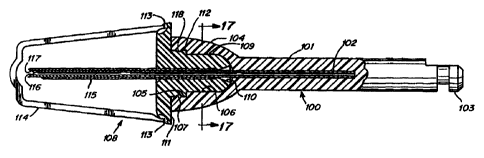
Figures 9-26. As shown in Figure 9, a drill coupling member
100 according to the second embodiment comprises a shaft 101,
an open housing 104 provided at one end of the shaft, and a
connecting portion 103 provided at an opposite end of the
shaft for establishing a connection to a conventional dental
drill handpiece. The open housing 104 includes a first
portion 105 having a round cross section, and a second
portion 106 having a square cross section. The round cross
section portion 105 and square cross section portion 106 can
be clearly seen in Figure 10, which shows a left side end view
of the drill coupling member 100. As shown in Figure 9, an
anticlog needle 102 extends from the shaft 101 through the
open housing 104. The anticlog needle 102 may be hollow as
shown in Figure 9, or solid, and the anticlog needle 102 may
also be flexible or rigid. More specifically, the anticlog
needle 102 may, for example, be a standard 27 gauge regular
wall needle having an oblique cutting edge 116. The anticlog
needle 102 may be replaced by a solid anticlog member made of
metal or a hard plastic material such as polyurethane. The
shaft 101, open housing 104 and connecting portion 103 of the
drill coupling member 100, moreover, may be formed of a
plastic material, with the anticlog needle 102 being insert
molded in the shaft 101. Thus, when the drill coupling member
100 is connected to a dental handpiece, the entire assembly of
the handpiece (not shown), the drill coupling member 100 and
the anticlog needle 102 can be removed from the drilling
needle member 108 (to be described below) in one motion.
Figures 11 and 12 are cross sectional views taken along
lines 11-11 and 12-12 shown in Figure 9, respectively, and
Figure 13 is a cross sectional view taken along line 13-13
shown in Figure 10. As shown in Figure 13, a friction grip
member 107 may be molded as shown in Figure 13, or a member
such as an 0-ring may be provided on the interior surface of
the round cross-sectional portion 105 of the open housing 104.
- 14 -
CA 02326200 2000-09-27
WO 99/52444 PCT/US99/07728
Figure 14 is a sectional view of a drilling needle
member 108 according to the second embodiment of the present
invention. The drilling needle member 108 comprises a
drilling needle housing 109 and a drilling needle shaft 115
extending therefrom. The drilling needle housing 109 has a
flared opening 110 at one end portion thereof, and a press
surface flange 111 at an opposite end portion thereof. The
surface llla of the housing 109 is preferably smooth so as to
not to damage tissue of the patient when the device is
installed or drilled into a bone of the patient. The surface
llla also has rounded edges lllb to further prevent damage to
gum tissue of the patient. As shown in Figure 14, the
drilling needle housing 109 may also be provided with a boss
112 which may have a groove 118 provided therein. The
friction grip protruding member 107 of Figure 13 snappingly
engages (due to the inherent resiliency of the plastic member)
in the groove 118 to improve retention of the drilling needle
member 108 in the drill coupling member 100.
As shown in Figure 14, a protective member such as a
drilling needle cap 114 may be coupled to the drilling needle
housing 109 via break away points 113. Alternatively, as
shown in Figure 19, the protective member may comprise an
alternately shaped member 125.
Also as shown in Figure 14, the drilling needle shaft 115
includes a passageway 119 therein communicating with a
delivery opening for delivering a fluid which is formed by
oblique cutting edge 117. The drilling needle shaft may, for
example, be a standard syringe-type needle having a 23 gauge
thin wall, and the drilling needle housing 109 and drilling
needle cap 114 may be formed of a plastic material, with the
drilling needle shaft 115 being insert molded in the drilling
needle housing 109.
- 15 -
CA 02326200 2000-09-27
WO 99/52444 PCT/US99/07728
Figure 15 is a right side end view of the drilling needle
shown in Figure 14. As shown in Figure 15, the drilling
needle housing 109 may have essentially a square cross section
with rounded corners, and is dimensioned such that it can be
frictionally fitted within the square cross sectional portion
106 of the open housing 104 of the drill coupling member 100.
For example, the drilling needle housing 109 may be formed
essentially in the shape of a square having a 2.50 mm legs or
faces, while the portion 106 of the open housing 104 of the
drill coupling member 100 in which the drilling needle housing
109 is to be frictionally fitted may be formed in the shape of
a square having 2.55 mm legs or faces.
Of course, drilling needle housing 109 and the portion
106 of the open housing 104 may also each be rectangular
(non-square) in shape, as shown in Figures 23 and 24.
Alternatively, the drilling needle housing of the drilling
needle member and the housing of the drill coupling member may
be formed in any compatible shapes such as oval or other non-
round shapes, such that a rotational driving force may be
applied therebetween without slippage.
Figure 16 is a partial sectional view of the drill
coupling member 100 and drilling needle member 108 according
to the second embodiment of the present invention in a
connected state.
As shown in Figure 16, the drilling needle member 108 is
connected to the drill coupling member 100 such that the
anticlog needle 102 is inserted through the flared opening 110
of the drilling needle member 108 and into the passageway 119
in the drilling needle shaft 115, and such that the drilling
needle housing 109 of the drilling needle member 108 is fitted
within the open housing 104 of the drill coupling member 100.
The oblique cutting edges 116 and 117 of the anticlog needle
and drilling needle shaft, respectively, may be offset as
- 16 -
CA 02326200 2000-09-27
WO 99/52444 PCT/US99/07728
shown in Figure 16 (in which position, the anticlog needle
provides some cutting action and enhances performance of the
drill), or they may be aligned together. In either case, the
anticlog needle 102 will serve to prevent cuttings or other
debris from entering the passageway 119 in the drilling needle
shaft 115 during drilling. This is especially the case when
the anticlog needle 102 is solid. If the anticlog needle is
hollow, any cuttings or debris entering the interior of the
anticlog pin 102 will be removed and discarded when the
anticlog pin 102 is removed and discarded, thus leaving
passageway 119 clear and free of cuttings or debris. The
friction grip member 107 provided on the interior surface of
the round cross sectional portion 105 of the open housing 104
of the drill coupling member 100 is sealingly engaged with the
groove 118 provided in the boss 112 provided on the drilling
needle housing 109 of the drilling needle member 108, and the
open housing 104 presses against flange 111 of the drilling
needle member 108.
As shown in Figure 19, the flange ill may have a convex
face 126 which presses against the bone when the hole in the
bone is drilled. The convex face 126 enables the drilling
needle member 108 to be rockingly leveraged when the drilling
needle member 108 is later removed from the bone.
The oblique cutting edges 116 and 117 of the anticlog
needle and of the drilling needle are preferably ground 20-30
degrees relative to the longitudinal axes thereof. Other
angles or drilling edge configurations could be used.
Preferably, the assembly of the drilling needle and anticlog
pin is rotated at about 20,000 rpm during the drilling
procedure. However, speeds of about 10,000 to 25,000 rpm
could be used with varying degrees of efficiency. Other
speeds, for example below 10,000 rpm or above 25,000 rpm could
also be used with varying degrees of efficiency, depending
upon the specific application.
- 17 -
CA 02326200 2000-09-27
WO 99/52444 PCT/US99/07728
Figure 17 is a cross sectional view taken along line 17-
17 shown in Figure 16. As shown in Figure 17, the drilling
needle housing 109 of the drill coupling member 100 is
frictionally fitted against the square cross sectional portion
106 within the open housing 104 of the drill coupling
member 100 so that a rotational driving force may be applied
from the drill coupling member 100 to the drilling needle
housing 109.
While the open housing 104 shown in Figures 16 and 17 is
a "female" member, and the square cross sectional portion 106
is a "male" member, which together provide a coupling so that
the members are non-rotational with respect to each other, the
configurations could be reversed. That is, as shown in
Figures 21 and 22 the housing of the drill coupling member 100
could comprise a projecting or male member 123 and the
drilling needle member 108 could comprise an open or female
portion 124 into which the male member 123 of the drilling
needle member 100 is inserted. In this manner, the drilling
needle 108 would also be non-rotationally coupled to the drill
coupling member 100 in an equivalent manner, such that a
rotational force applied to the.drill coupling member 100 is
transmitted to the drilling needle member to enable drilling,
as described hereinabove.
Other arrangements for providing a non-rotational
coupling between the drill coupling member 100 and the
drilling needle member 108 can also be used. For example, as
shown in Figures 25 and 26, an alternate arrangement is shown
wherein the drill coupling member 100 comprises a
semi-circular housing 119 which is adapted to be engaged with
a corresponding semi-circular housing 120 of the drilling
needle member 108. In this alternate arrangement, the
semi-circular housing 120 of the drilling needle member 108
preferably includes a strengthening sleeve 121 which surrounds
- 18 -
CA 02326200 2000-09-27
WO 99/52444 PCT/US99/07728
the drilling needle shaft 115 to protect the drilling needle
shaft from breakage during driving by a drill. The .
strengthening sleeve 121 is inserted into an open portion 122
of the semi-circular housing 119 of the drill coupling member
100, and serves to ensure that the drilling needle shaft is
rotatingly driven in a secure manner.
As shown in Figure 18, a storage and disposal casing 118
may be provided in which the disposable anesthesia delivery
apparatus can be removably stored. After usage, the
disposable anesthesia delivery apparatus can be reinserted
into the casing 118 for safe disposal.
The procedural operations for applying anesthesia in
accordance with the second embodiment of the present invention
will now be described. The drill coupling member 100 is
preferably pre-assembled to the drilling needle member 108,
and the preassembled unit is connected to a conventional
dental drill (handpiece). Alternatively, the drill coupling
member 100 may be first connected to a conventional dental
drill via the connecting portion 103, and the drilling needle
member 108 may then be coupled to the drill coupling member
100 as described above. The protective member 125 is then
broken off (by bending protective member 125) from the
drilling needle member 108 to expose the drilling needle shaft
115 with the anticlog needle 102 inserted therein, as shown in
Figure 19. The dental drill is then used to apply a
rotational driving force via the drill coupling member 100 to
the drilling needle housing 109 of the drilling needle member
108 so that the drilling needle shaft 115 with the anticlog
needle 102 inserted therein is rotatingly driven to drill a
hole in the jawbone of a patient. In addition, a pressing
force may also be applied via the flange 111 of the drilling
needle member 108 so as to assist the drilling operation. The
pressing force and rotational driving force are applied until
the flange 111 presses against or contacts the gums of the
- 19 -
CA 02326200 2000-09-27
WO 99/52444 PCT/US99/07728
patient, thereby ensuring that the drilling needle member 108
has been fully inserted in the drilled hole.
Alternatively, the drilling needle shaft 115 with the
anticlog needle 102 inserted therein may be inserted into the
jawbone by means of manual pushing and/or manual rotation, or
by other means of applying a necessary force.
Once the insertion operation is completed, the drill
coupling member 100 is disengaged from the drilling needle
member 108, as shown in Figure 20. This is done in a manner
such that the drilling needle shaft 115 is left inserted in
the drilled hole, for example, by exerting a forward pressing
force on the outer edges of the flange 111 of the drilling
needle member 108 while at the same time exerting a rearward
withdrawal force on the drill coupling member 100.
As mentioned above, during the insertion operation, the
anticlog needle 102 prevents cuttings and other debris from
entering the passageway 119 in the drilling needle shaft 115.
Accordingly, upon withdrawal of the anticlog needle 102, a
clear conduit into the interior of the bone of the patient is
established via the passageway 119 in the drilling needle
shaft 115 which remains inserted in the drilled hole.
A conventional syringe may then be used to inject an
anesthetic or other fluid into the interior of the bone of the
patient via the passageway 119. More specifically, a needle
extending from a conventional syringe is inserted through the
flared opening 110 of the drilling needle member 108 and into
the passageway 119 in the drilling needle shaft 115. The
needle of the syringe must, of course, have a gauge smaller
than the gauge of the drilling needle shaft 115 such that the
needle of the syringe may be inserted into the passageway 119.
Preferably, a sufficient clearance is provided between the
drilling needle shaft 115 and the needle of the syringe such
- 20 -
CA 02326200 2000-09-27
WO 99/52444 PCT/US99/07728
that a build up of pressure is avoided when injecting the
anesthetic or other fluid and so that the needle of the
syringe may be easily removed from the drilling needle
shaft 115. For example, the needle of the syringe may, like
the anticlog needle 102, be a standard 27 gauge regular wall
needle.
Once the anesthetic or other fluid has been injected, the
needle of the syringe is then withdrawn from the
passageway 119 in a manner such that the drilling needle
shaft 115 is left inserted in the bone of the patient. The
drilling needle shaft 115 and the drilling needle member 108
preferably remain in the inserted position in the bone during
the entire dental procedure. Additional anesthetic or other
fluid may then be applied, if and when necessary, via the
passageway 119 in the drilling needle shaft which is left
inserted in the bone of the patient. Accordingly, a direct,
reusable communication path is established and maintained into
the jawbone of the patient which enables simple reinjection of
anesthetic or other fluid, if and when necessary, during
performance of a dental procedure.
The above described advantageous effect of the second
embodiment of the claimed present invention is enabled to be
achieved because the drilling needle member 108 which is left
inserted in the jawbone of the patient is sufficiently small
and unobtrusive so as not to interfere with the dental
procedure which is being performed. Preferably, the drilling
needle member 108 projects no more than about 5 mm from the
gum surface, when the device is used in dental applications.
The drilling needle member 108 may therefore be left inserted
in the jawbone of the patient throughout a dental procedure,
and need only be removed once the dental procedure is
completed. At the end of the procedure, in order to remove
the drilling needle member 108 from the jawbone of the
patient, the boss 112 on the drilling needle member may be
- 21 -
CA 02326200 2000-09-27
WO 99/52444 PCT/US99/07728
gripped and pulled either manually or, for example, by a
pliers-type tool or a U-shaped tool which is adapted to grip
the groove 118 provided in the boss 112.
Preferably, the members 100 and 108 are injection molded
of polystyrene with 20% calcium carbon, with the respective
needle members 115 and 102 insert molded therein. Other
materials (such as other plastics) could be used in place of
the polystyrene material.
Additional advantages and modifications will readily
occur to those skilled in the art. Therefore, the invention
in its broader aspects is not limited to the specific details,
representative devices, and illustrated uses and examples
shown and described herein. Accordingly, various features of
the respectively disclosed embodiments can be used with other
embodiments, and various modifications may be made without
departing from the spirit or scope of the general inventive
concept of the present invention as defined by the appended
claims and their equivalents.
- 22