Language selection

Search

Patent 2326241 Summary

Third-party information liability

Some of the information on this Web page has been provided by external sources. The Government of Canada is not responsible for the accuracy, reliability or currency of the information supplied by external sources. Users wishing to rely upon this information should consult directly with the source of the information. Content provided by external sources is not subject to official languages, privacy and accessibility requirements.

Claims and Abstract availability

Any discrepancies in the text and image of the Claims and Abstract are due to differing posting times. Text of the Claims and Abstract are posted:

  • At the time the application is open to public inspection;
  • At the time of issue of the patent (grant).
(12) Patent: (11) CA 2326241
(54) English Title: ULTIMATE VENT
(54) French Title: EVENT SUPREME
Status: Deemed expired
Bibliographic Data
(51) International Patent Classification (IPC):
  • F24F 13/20 (2006.01)
  • F24F 13/08 (2006.01)
  • F24F 13/28 (2006.01)
(72) Inventors :
  • TOCHER, JOHN WILLIAM (Canada)
(73) Owners :
  • TOCHER, JOHN WILLIAM (Canada)
(71) Applicants :
  • TOCHER, JOHN WILLIAM (Canada)
(74) Agent: NA
(74) Associate agent: NA
(45) Issued: 2004-04-13
(22) Filed Date: 2000-11-30
(41) Open to Public Inspection: 2001-10-14
Examination requested: 2001-08-08
Availability of licence: N/A
(25) Language of filing: English

Patent Cooperation Treaty (PCT): No

(30) Application Priority Data: None

Abstracts

English Abstract

An inexpensive fresh air intake pre-filtering device for make-up air is disclosed for use with a circulating forced air heating system that is installed on an outside wall of a building. The device is comprised of a polyethylene material, with an outer flange for securing the fresh air intake to the exterior wall surface as a retrofit or an installation on new dwellings. The fresh air intake housing is structured to include an aluminium frame, two sided raised pattern grill of a RX PolyMed filter medium, manufactured from 100% synthetic fibres. This is to prevent vermin, insects, pollens, and other pollutants from passing through, while permitting the ten percent of air flow required by the National and Regional Building Codes far residential housing. This washable filter is easily removed or installed by the pull tab on the front of the vent housing. This pre-filtering device is designed to prevent snow and rain from entering the fresh air intake duct.


French Abstract

Un dispositif de pré-filtration d'entrée d'air frais bon marché pour fabriquer de l'air est divulgué en vue d'une utilisation avec un système de chauffage à air pulsé de circulation qui est installé sur une paroi extérieure d'un bâtiment. Le dispositif est composé d'un matériau de polyéthylène, ayant une bride externe pour fixer l'entrée d'air frais à la surface de paroi extérieure comme une rénovation ou une installation sur de nouvelles habitations. Le boîtier à entrée d'air frais est structuré pour comprendre un cadre en aluminium, une grille à motif surélevée à deux côtés d'un support de filtre PolyMed RX, fabriquée à partir de fibres 100 % synthétiques. Ceci doit empêcher les animaux indésirables, les insectes, les pollens et autres polluants de passer à travers celle-ci, tout en permettant les dix pour cent de l'écoulement d'air requis par les codes de construction nationaux et régionaux pour un logement résidentiel. Ce filtre lavable est facilement retiré ou installé par la languette de tirage sur la partie avant du boîtier à évent. Ce dispositif de pré-filtration est conçu pour empêcher la neige et la pluie d'entrer dans le conduit d'entrée d'air frais.

Claims

Note: Claims are shown in the official language in which they were submitted.


THE EMBODIMENTS OF THE INVENTION IN WHICH AN
EXCLUSIVE PROPERTY OR PRIVILEGE IS CLAIMED ARE
DEFINED AS FOLLOWS

Claim 1

A pre-filtering device for removing contaminants from fresh air
supplied to a forced air heating circulating system in a bulling
comprising:
a one piece polypropylene moulded vent having a planar base
adapted to be installed on an outside surface of the building, the
base having a circular opening and an inverted flange along the
circumference of the opening, the inverted flange protruding
outwardly from the base, and thereafter inwardly creating a
circumferential groove opened toward the wall to accommodate a
fresh air supply duct protruding from the wall of the building
through an air intake opening;
the vent further comprising a weather protecting housing in a
shape of a hood extended from the base over the intake opening,
the open end of the hood having an integrally moulded seat
having a front and rear end, and a moisture resistant filter placed
in the seat, the seat having a lock and a pull tab in the front end
to release and remove the filter from the seat.

Claim 2
The pre-filtering device as defined in claim 1 wherein said base with
the inverted flange is flush mounted to a metal base of an existing
air inlet after removal of an existing weather protecting housing.

Claim 3
The prefiltering device as defined in claim 1 wherein said removable
filter consists of an aluminium frame, raised pattern screen, and one
hundred percent moisture resistant synthetic fibre material.


8

Description

Note: Descriptions are shown in the official language in which they were submitted.


CA 02326241 2003-10-30
Fidd of The Invention
This invention is in the field of furnace forced air heating, air circulation
for make-np air.
2 of 8

CA 02326241 2003-10-30
Background of The Invention
A supply of make-up and combustion sir is required for buildings
with forced air heating from furnaces with a combustion chamber that
burns a f5uel of natural gas or oil. Buildings made airtight rely on the
make-up air supply to maintain a neutral or positive pressure so products
from combustion don't enter the inhabited areas. While the forced air fan
is operating it will draw in through the fresh air intakes upward of 80 to
125 cfm or what calculates into 10'x. of the make-up required for the
building's particular furnace circuling system.
Where acr~xns are required on air intakes supplying make,-up sir,
the building code requires that the screens less than 1/4 " or 6 mm, it's
gross area shall be three times greater than the duct it serves, they shall
be removable without any special tools and made of a none corrosive
resistant material.
In the art, a device has been introduced for supplying make-up air
to the forced air furnace circulating system as shown by, Rudd, Armio CA
2245135, is known to use the same standard screen openings, l/4" or 6mm,
which is not removable for cleaning on the fresh air intakes. Screens of
this nature are known to plug up with debris, freeze up with frost and
snow, imposing d~culty on the air intakes to supply the makes-up air,
there by creating a negative pressure and allowing products of combustion
into the inhabited areas, possibly at unsafe levels.
Studies show these air intakes develop a build up over time by
allowing insects, mice, pollens, dust mites, allergens and air borne bacteria
to cuter the furnace's circulating system, this accumulation and
confinement has raised some health concerns.
3 of 8

CA 02326241 2003-10-30
Objects of 3'he Invention
It is the general object of the invention to provide a fresh air intake that
will over come the said aisadvantages~in the Background of the invention
in the make-up air circulating system.
It is also tpe object o3 the invention to create a better yuslity o~f supply
make-up air for the home.
It is another object of this invention to prevent freezing and plugging up
by outside elements.
It is another object of this invention to create a screen that can be easily
removed for cleaning and replaced without the use of any special tools.
4 of 8

CA 02326241 2003-10-30
Summary of The Invention
The invention is directed to a furnace forced air heating make-up
air circulating system for a building, relating more to residential homes.
A pre-filtering device being mounted on an outside wall of a
building and connected to the make-up air inlet conduit to the return air
duct accomplishes a better quality make-up air.
Further, in accordance with this invention, while the furnance fan
is operating the 10% of make-up air required is being drawn through the
pre-filtering device stops most pollutants such as dust mites, pollens,
allergens, and airborne bacteria as well as insects, before entering through
the wall and into the conduit to the return air duct.
Further, in accordance with this invention, an aluminium frame
with a raised pattern grill allows the frost to build up and dissipate
through the filter medium in the winter months.
Further, in accordance with this invention, there are no special
tools required for installing, removing for service, or cleaning of the
screen.
In the following detailed description and drawings that follow, a
more complete understanding of the invention will be obtained.
5 of 8

CA 02326241 2003-10-30
Description of the Drawings
Fig. 1 shows a side evalution view of the pre-filtering device with its
specifications
Fig. 2 is a side evaluation view showing the embodiments of the invention
Fig. 3 this is a view showing a one-piece housing and flange for
mounting on an outside wall with the tab for releasing the filter
Fig. 4 is showing a rear view that's placed against the wall for mounting
as well as the groove in the inverted flange
Fig. 5 this is the same as figure No. 4 showing the inverted flange and
depth of the intake opening
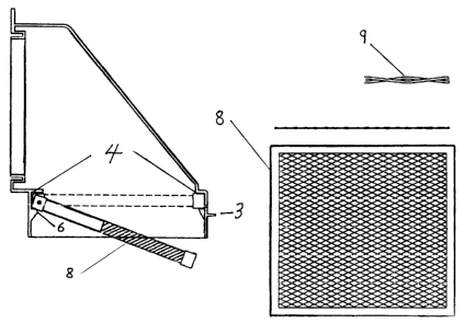
Fig. 6 shows a side evaluation view of how the filter is installed and
uninstalted with a view of the filter and screen with it's raised
pattern grill
6 of 8

CA 02326241 2003-10-30
Detailed Description of Preferred Embodiments
As shown in the drawings, a fresh air intake pre-filtering device is
made as a one-piece, polyethylene injected moulded veDt adapted to be
mounted on an outside wall of a building. The vent has a planar base (1)
with an opening, and an integrally connected inverted flange around the
opening. The inverted flange (5) is invert in such a manner that it creates
a circumferential groove open towards the wall. A fresh air conduit which
is inserted into a fresh air intake opening in the building wall is placed in
the groove allowing the vent to be flush mounted on the wall.
A weather protecting housing (2) or hood protrudes from the base
above the opening and the inverted flange and has at its facing
downwardly open end a screen and a filter (8), both easily removable
for cleaning. the screen and filter are placed in a seat (4) moulded in the
opening of the hood and are easily released and removed by pulling a
pull tab (3) at the front and of the seat. In order to reinstall the filter
and screen, both of them should be inserted towards the back end of the
seat and placed at 120 degree angle on two rear tabs then the front should
be raised to achieve horizontal position of the filter and screen locking the
latter tight in the seat. The requirements for the filter (8) are the
folloR~ing: a frame of the filter and the screen (9) have to be made of a
corrosion and moisture resistant material, and having low initial pressure
resistance since filters have tendency to freeze up.
The best combination to accomplish desired filtering and fresh air
supplying action consists of the following:
- an aluminium frame, e.g. -7. 5" by 8. 0", enclosing a screen made as a
two sided raised pattern grill;
a filter made of 100% synthetic fibre;
- 0.06 w.g. initial pressure resistance at 100 cfm.
The raised pattern grill allows the frost to build up, keeping it off
the filter and at the same time leaving openings for the air to flow
through.
The venting and filtering device can be installed in a new system as
well as in an existing one after an existing rain cap is removed.
The filter may be made from a material distributed in Canada
under the trade name RX PolyMed.
7of8

Representative Drawing
A single figure which represents the drawing illustrating the invention.
Administrative Status

For a clearer understanding of the status of the application/patent presented on this page, the site Disclaimer , as well as the definitions for Patent , Administrative Status , Maintenance Fee  and Payment History  should be consulted.

Administrative Status

Title Date
Forecasted Issue Date 2004-04-13
(22) Filed 2000-11-30
Examination Requested 2001-08-08
(41) Open to Public Inspection 2001-10-14
(45) Issued 2004-04-13
Deemed Expired 2016-11-30

Abandonment History

There is no abandonment history.

Payment History

Fee Type Anniversary Year Due Date Amount Paid Paid Date
Application Fee $150.00 2000-11-30
Advance an application for a patent out of its routine order $100.00 2001-08-08
Request for Examination $200.00 2001-08-08
Maintenance Fee - Application - New Act 2 2002-12-02 $50.00 2002-09-09
Maintenance Fee - Application - New Act 3 2003-12-01 $50.00 2003-10-10
Final Fee $150.00 2004-01-27
Maintenance Fee - Patent - New Act 4 2004-11-30 $50.00 2004-09-29
Maintenance Fee - Patent - New Act 5 2005-11-30 $100.00 2005-11-30
Maintenance Fee - Patent - New Act 6 2006-11-30 $100.00 2006-11-30
Maintenance Fee - Patent - New Act 7 2007-11-30 $100.00 2007-09-21
Maintenance Fee - Patent - New Act 8 2008-12-01 $100.00 2007-09-21
Maintenance Fee - Patent - New Act 9 2009-11-30 $100.00 2009-11-25
Maintenance Fee - Patent - New Act 10 2010-11-30 $125.00 2009-11-25
Maintenance Fee - Patent - New Act 11 2011-11-30 $125.00 2010-11-04
Maintenance Fee - Patent - New Act 12 2012-11-30 $125.00 2012-07-18
Maintenance Fee - Patent - New Act 13 2013-12-02 $125.00 2013-10-02
Maintenance Fee - Patent - New Act 14 2014-12-01 $125.00 2014-09-19
Owners on Record

Note: Records showing the ownership history in alphabetical order.

Current Owners on Record
TOCHER, JOHN WILLIAM
Past Owners on Record
None
Past Owners that do not appear in the "Owners on Record" listing will appear in other documentation within the application.
Documents

To view selected files, please enter reCAPTCHA code :


To view images, click a link in the Document Description column. To download the documents, select one or more checkboxes in the first column and then click the "Download Selected in PDF format (Zip Archive)" or the "Download Selected as Single PDF" button.

List of published and non-published patent-specific documents on the CPD .

If you have any difficulty accessing content, you can call the Client Service Centre at 1-866-997-1936 or send them an e-mail at CIPO Client Service Centre.


Document
Description 
Date
(yyyy-mm-dd) 
Number of pages   Size of Image (KB) 
Representative Drawing 2001-09-19 1 5
Abstract 2003-05-27 1 35
Claims 2003-05-27 1 39
Description 2003-05-27 6 166
Claims 2003-10-30 1 38
Abstract 2003-10-30 1 24
Description 2003-10-30 6 146
Representative Drawing 2003-11-28 1 24
Cover Page 2001-10-05 1 28
Abstract 2001-01-23 1 13
Claims 2001-01-23 1 22
Description 2001-01-23 2 57
Abstract 2002-05-01 1 37
Claims 2002-05-01 1 59
Drawings 2002-05-01 6 123
Description 2002-05-01 2 96
Description 2000-11-30 1 17
Drawings 2000-11-30 1 18
Drawings 2001-08-08 12 180
Cover Page 2004-03-11 1 54
Correspondence 2004-01-27 1 85
Correspondence 2001-01-04 1 2
Assignment 2000-11-30 2 102
Correspondence 2001-01-23 10 223
Correspondence 2001-05-17 1 2
Prosecution-Amendment 2001-08-08 14 237
Correspondence 2001-08-08 2 57
Prosecution-Amendment 2001-08-17 1 12
Prosecution-Amendment 2001-10-30 2 64
Correspondence 2001-10-15 1 50
Correspondence 2001-11-01 1 13
Prosecution-Amendment 2002-05-01 13 423
Prosecution-Amendment 2002-12-03 3 101
Prosecution-Amendment 2003-01-08 5 235
Prosecution-Amendment 2003-01-20 6 288
Prosecution-Amendment 2003-05-27 10 278
Prosecution-Amendment 2003-08-18 3 118
Fees 2003-10-10 1 15
Prosecution-Amendment 2003-10-30 10 256
Fees 2002-09-09 1 120
Fees 2004-09-29 1 65
Correspondence 2005-10-05 4 165
Correspondence 2005-12-22 1 13
Fees 2005-11-30 1 18
Fees 2006-11-30 1 42
Correspondence 2007-10-04 2 64
Fees 2007-09-21 1 68
Fees 2009-11-25 2 70
Fees 2010-11-04 5 185
Fees 2012-07-18 1 23
Returned mail 2016-01-27 2 83
Fees 2013-10-02 1 75
Fees 2014-09-19 1 22
Correspondence 2015-09-01 2 94