Note: Descriptions are shown in the official language in which they were submitted.
CA 02326351 2000-09-27
Wa 99/49818 PCT/US99/03907
PROSTHETIC SYSTEM
Backaround gf the Invention
The present invention relates generally to a
prosthetic system, and more particularly to mechanical and
biological spinal prostheses, as well as a method and
apparatus for inserting the prostheses between vertebrae of
a spine.
Degenerative disease of the spine, which is
caused by stresses imposed on the spine by trauma and
normal loading, as well as genetics and other factors,
results in abnormal motion between vertebrae beyond normal
limits. Eventually, if uncorrected, the degenerative
processes can lead to pain; deformity, musculoskeletal
dysfunction and neurologic dysfunction. When other
measures fail to alleviate these symptoms, surgical
intervention is required.
Typically, the surgical intervention involves
implanting mechanical and/or biological prostheses between
affected vertebrae of the spine to immobilize the affected
vertebrae and eventually fuse them together. Mechanical
prostheses restore anatomical curvature to the spine,
prevent deformity from progressing and immobilize the
vertebrae to promote fusion of the vertebrae. Biological
prostheses are sometimes used, alone or in combination with
mechanical prostheses, to promote bone growth between the
vertebrae, thereby facilitating fusion of the vertebrae.
The biological protheses are generally made of bone
harvested from the patient or some other donor.
According to a principle known as Wolff's Law,
bone growth is stimulated and directed by loading the bone
which occurs naturally as a person moves. For instance,
growth of bone through biological prostheses may be
stimulated by loading the prostheses. However,
conventional mechanical prostheses are relatively rigid and
do not permit the biological prostheses to be loaded in a
CA 02326351 2000-09-27
WU~ 99/49818 PCT/US99/03907
2
natural manner due to "stress shielding". : As a result,
bone growth is not stimulated when biological prostheses
and conventional mechanical prostheses are used in
combination. Accordingly, the efficacy of the prosthetic
system is reduced when biological and conventional
mechanical prostheses axe used together.
Biological prostheses conduct and direct bone
growth from exposed recipient bone. When biological
prostheses are implanted between vertebrae, bone grows
inward from the facing surfaces of the vertebrae adjacent
the biological prosthesis, eventually growing together and
fusing the vertebrae. As will be appreciated by those
skilled in the art, the speed at which the bone grows and
the overall success of the prosthetic system is greatly
affected by the surface area of the vertebrae exposed to
the biological prosthesis. However, many prior art
mechanical prostheses contact the adjacent vertebrae over
large areas and prevent the biological prostheses from
contacting the vertebral surfaces. Thus, bone growth is
inhibited, thereby reducing the efficacy of the prosthetic
system.
Further, many conventional biological prostheses
are composed only of fragments of bone. One desirable
aspect of these "dry" prostheses is that they stay in
position between vertebrae. However, it is sometimes
desirable to add liquid to the prostheses. For instance,
liquid growth factors are added to the biological
prostheses for stimulating bone growth. However, the
liquid additives make the prostheses highly flowable. As
a result, available biological protheses containing growth
factors frequently flow out from position between the
vertebrae, thereby reducing their efficacy.
In addition, conventional mechanical prostheses
and the conventional tools used to implant them have
relatively wide profiles, requiring large portions of the
CA 02326351 2000-09-27
WO' 99/49818 PCTNS99/03907
3
discs or surrounding structures and tissues such as
pedicles, facets and ligaments to be removed before the
prosthesis can be inserted. However, experience has shown
that the more material removed from around the vertebrae,
the more the trauma and the greater the chance for
instability and failure of the surgery. Further, the wide
profiles of conventional prostheses and tools increase the
likelihood of permanent injury to the spinal cord and nerve
roots, especially when the prostheses are inserted in the
upper spine.
Summary of the Invention
Among the several objects of the present
invention may be noted the provision of a method and
apparatus which correct and relieve pain associated with
segmental instability of the spine; the provision of such
a method and apparatus which limit the motion of adjacent
vertebrae of a spine; the provision of such a method and
apparatus which facilitate fusion of adjacent vertebrae;
the provision of such a method and apparatus which promote
bone and blood vessel growth between adjacent vertebrae;
the provision of such a method and apparatus which minimize
the risk of injury to the surrounding vertebrae and
structures; and the provision of such a method and
apparatus which permit introduction of a fluid biological
prosthesis having sufficient viscosity to remain in
position between vertebrae.
Briefly, the present invention includes a
surgical method of inserting a prosthetic system between
first and second vertebrae spaced by a disc to limit motion
between and to facilitate fusion of the first and second
vertebrae. The method comprises the steps of exposing the
first and second vertebrae and the disc, excising at least
a portion of the disc from between the first and second
vertebrae, and scraping the cartilage from facing surfaces
CA 02326351 2000-09-27
WUr 99149818 PCTNS99/03907
4
of the vertebrae to expose the facing surfaces. The method
also includes the steps of spacing the first and second
vertebrae by a selected distance and simultaneously cutting
grooves in the facing surfaces of the vertebrae using a
S cutting tool having opposing blades. A mechanical
prosthesis is anchored in the grooves cut in the facing
surfaces of the vertebrae so that the prosthesis extends.
between the vertebrae and limits motion between the
vertebrae. In addition, the method includes the step of
packing bone graft material between the vertebrae and
around the mechanical prosthesis to promote bone growth
between and facilitate fusion of the vertebrae.
In another aspect, the present invention includes
a spinal prosthesis for insertion during surgery in a space
between first and second vertebrae of a spine of a patient.
The prosthesis comprises a central support sized and shaped
for insertion between the first and second vertebrae. The
support has a height measured between a top and a bottom
approximately equal to a selected spacing between the
vertebrae. The prosthesis also includes upper and lower
flex members extending from the top and bottom of the
central.support, respectively, for engaging the first and
second vertebrae. The upper and lower members have a
stiffness sufficiently small to permit the members to flex
elastically toward each other under loading from the
vertebrae.
In yet another aspect, the invention includes a
spinal prosthesis comprising a central support, as well as
upper and lower anchors positioned at the top and bottom of
the support, respectively, for anchoring the support
between the first and second' vertebrae. Each anchor
includes a sharp edge for holding the anchor in position
with respect to the respective vertebra.
In still another aspect, the present invention
includes a spinal prosthesis comprising a central support
CA 02326351 2000-09-27
W0~ 99!49818 PCTNS99/03907
and at least one stiffener extending from the support for
strengthening the support to inhibit flexing thereof.
In addition, the present invention includes a set
of surgical instruments for inserting a prosthetic system
5 between first and second vertebrae to limit motion between
and/or to facilitate fusion of the vertebrae. The set of
instruments comprises a spacer for positioning the first
and second vertebrae in a selected orientation and spacing
the vertebrae by a selected distance. The spacer has a
tapered tip for facilitating insertion of the spacer
between the vertebrae and opposing surfaces for engaging
facing surfaces of the vertebrae thereby to position and
space them. The set of instruments also includes a cutting
tool having opposing blades for cutting grooves
simultaneously in the facing surfaces of the first and
second vertebrae and a guard adapted for attachment to the
spacer. The guard has a passage sized for receiving the
cutting tool to guide the tool between the facing surfaces
of the vertebrae and to prevent the blades from errantly
cutting structures surrounding the vertebrae.
Still further, the present invention includes a
syringe for injecting bone graft material between first and
second vertebrae to promote fusion of the vertebrae. The
syringe comprises a body having a hollow interior and a
nozzle communicating with the interior for delivering bone
graft material from the hollow interior to a_space between
the vertebrae. In addition, the syringe includes a piston
reciprocally receivable within the hollow interior of the
cylindrical body for forcing bone graft material from the
hollow interior through the nozzle. The piston and body
have interengaging screw threads which drive the piston
toward the nozzle to force bone graft material through the
nozzle upon rotation of the threads relative to each other.
Moreover, the present invention includes a
syringe for injecting bone graft material comprising a
CA 02326351 2000-09-27
WO~ 99/49818 PCT/US99/03907
6
cylindrical body and a piston reciprocally receivable
within a hollow interior of the cylindrical body for
forcing bone graft material from the hollow interior
through a nozzle. In addition, the syringe includes a
heating element in thermal communication with the hollow
interior of the cylindrical body for heating the bone graft
material to a predetermined temperature.
Further, the present invention includes a syringe
for injecting bone graft material comprising a cylindrical
body having a hollow interior and a nozzle communicating
with the interior for delivering bone graft material from
the hollow interior to a space between the vertebrae. The
syringe also includes a piston reciprocally receivable
within the hollow interior of the cylindrical body for
forcing bone graft material from the hollow interior into
the nozzle. The piston has a hole extending through the
piston aligned with the nozzle. In addition, the syringe
comprises a plunger reciprocally received within the hole
extending through the piston for forcing bone graft
material through the nozzle.
The present invention also includes a fluid bone
graft material for insertion during surgery in a space
between first and second vertebrae of a spine of a patient
to facilitate fusion of the first and second vertebrae.
The material comprises a plurality of bone particles and a
growth factor for stimulating bone growth. The material is
sufficiently viscous to remain in place between the first
and second vertebrae under loading by the vertebrae.
Other objects and features of the present
invention will be in part apparent and in part pointed out
hereinafter.
Brief Description of the Drawings
Fig. 1 is a side elevation of a mechanical
prosthesis of the present invention in a space between
CA 02326351 2000-09-27
W0~99/49818 PGT/US99/03907
7
first and second vertebrae shown in partial section for
clarity;
Fig. 2 is a top plan of two mechanical prostheses
shown in relation to a vertebra;
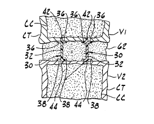
Fig. 3 is a cross section taken in the plane of
line 3-3 of Fig. 2 showing two mechanical prostheses and a
biological prosthesis between two vertebrae;
Fig. 4 is a perspective of the mechanical
prosthesis;
Fig. 5 is a front elevation of a spacer of the
present invention;
Fig. 6 is a side elevation of the spacer of Fig.
5;
Fig. 7 is a front elevation of a guard of the
present invention;
Fig. 8 is a bottom plan of the guard;
Fig. 9 is a front elevation of a cutting tool of
the present invention;
Fig. 10 is a side elevation of the cutting tool;
Fig. 11 is a bottom plan of the cutting tool;
Fig. 12 is a top plan of a depth gauge of the
present invention;
Fig. 13 a front elevation of the depth gauge;
Fig. 14 is a front elevation in partial section
of a syringe of the present invention;
Fig. 15 is a front elevation in partial section
of a second embodiment of a syringe of the present
invention;
Fig. 16 is an enlarged, fragmentary front
elevation in partial section of the second embodiment of
the syringe;
Fig. 17 is a side elevation of the spacer of Fig.
5 shown inserted between vertebrae of a spine;
CA 02326351 2000-09-27
WO 99/49$18 PCT/US99/03907
8
Fig. 18 is a side elevation :of a second
embodiment of a spacer of the present invention shown
inserted between vertebrae;
Fig. 19 is an elevation similar to Fig. 17
showing the guard engaging the spacer;
Fig. 20 is an elevation similar to Fig. 19
showing the cutting tool received in the guard;
Fig. 21 is an elevation similar to Fig. 20
showing the depth gauge installed on the cutting tool;
Fig. 22 is a cross section taken in the plane of
line 22-22 in Fig. 21;
Fig. 23 is an elevation similar to Fig. 21
showing the cutting tool advanced between the vertebrae;
and
Fig. 24 is a cross section taken in the plane of
line 24-24 in Fig. 23.
Corresponding reference characters indicate
corresponding parts throughout the several views of the
drawings.
detailed Description of the Preferred Embodiment
Referring now to the drawings and in particular
to Figs. 1-4, a mechanical prosthesis is indicated in its
entirety by the reference numeral 30. The prosthesis 30
generally comprises a central support 32, upper and lower
flex members 36, 38 (respectively), upper and lower anchors
42, 44 {respectively) and stiffeners 48. As will be
explained in greater detail below, the prosthesis is
adapted for insertion between a first vertebra Vl and a
second vertebra V2 of a spine, generally designated S.
The central support 32 is preferably a
quadrilateral panel having a length greater than its
height, and a thickness significantly less than its height.
Preferably, the support 32 has a height measured between
its top and bottom approximately equal to a selected
CA 02326351 2000-09-27
Wa''99/49818 PCTNS99/03907
9
spacing between the first and second vertebrae V1, V2.
Usually, the selected spacing refers to a spacing slightly
larger than the most desirable spacing practicably
obtainable between the vertebrae so that the most desirable
spacing practicably obtainable is achieved between the
vertebrae after the vertebrae are seated on the anchors 42,
44 of the prosthesis 30 as will be explained below.
However, other spacings may also be used without departing
from the scope of the present invention. As illustrated in
i0 Fig. 1, the front end of the support (to the left as shown)
is taller than its back end, so that when the prosthesis 30
is inserted, the first vertebra V1 is angled relative to
the second vertebra V2. As will be explained in more
detail below, the front and back ends of the support may
have equal heights without departing from the scope of the
present invention. The support 32 is thin to reduce the
volume of the prosthesis 30 and to present a narrow profile
yet provide enough strength to support the spine S. It is
contemplated that the lateral faces of the support may be
grooved, knurled or otherwise patterned to improve gripping
when the prosthesis 30 is installed.
The prosthesis 30 may be constructed of numerous
different biocompatible materials. It may be a metallic,
nonmetallic or composite material, but the preferred
construction is a carbon fiber-reinforced polymer
composite. It is also envisioned that the polymer may
include other carbon-based organic molecules (a
biomolecular substrate) for enhancing bone and blood vessel
growth (osteogenesis, osteoconduction and angiogenesis)
through and/or around the prosthesis. Additionally,
mineral salts may be added to the substrate to enhance
stability and incorporation of the material. Although
materials having other characteristics may be used without
departing form the scope of the present invention, in the
preferred embodiment the strength of the material in
CA 02326351 2000-09-27
WO 99/49818 PCT/US99/03907
compression, torsion and shear and the modulus of
elasticity closely approximate the strength and elasticity
of the cortical bone CT forming the outer layer of the
vertebrae V1, V2. In the case of carbon fiber-reinforced
5 materials, this can be accomplished by weaving the fibers
in a multidirectional pattern, as will be understood by
those skilled in the art. Preferably, the material is
radiolucent to allow healing to be monitored and imaged
without distortion using standard radiographic techniques.
10 Most preferably, the reinforcing material and/or the
substrate material of the prosthesis is absorbable by the
patient so that the stiffness of the prosthesis 30
decreases over time after it is inserted in the spine S.
Although other materials may be used without departing from
the scope of the present invention, the material of the
preferred embodiment is a carbon fiber reinforced carbon
composite material such as Integraft polymer coated carbon
fiber available from Hexcel Medical of Livermore,
California. Both of these preferred materials are
radiolucent and absorbable, however other materials which
are non-radiolucent and/or non-absorbable are also within
the scope of the present invention.
As illustrated in Fig. 3, two upper and two lower
flex members 36, 38 extend laterally outward from the
support 32 for engaging the first and second vertebrae V1,
V2, respectively, to distribute load across the vertebrae
and thereby to prevent invagination of the support into the
soft cancellous bone CC inside the vertebrae. The flex
members 36, 38 have stiffness coefficients that are
sufficiently small to permit the members to flex
elastically toward each other when loaded by the vertebrae
V1, V2. The flex members 36, 38 are designed to return to
their undeformed positions to restore the selected spacing
between the vertebrae V1, V2 when the load is removed. The
upper flex members 36 engage a lower surface of the first
CA 02326351 2000-09-27
W0~99/49818 PCT/US99/03907
11
vertebra V1 and the lower flex members 38 engage an upper
surface of the second vertebra V2. Preferably, the flex
members 36, 38 are formed integrally with the support 32.
Although the flex members 36, 38 may be longer or shorter
without departing from the scope of the present invention,
the flex members of the preferred embodiment have lengths
which are substantially equal to the length of the support
32. Moreover, the flex members 36, 38 of the preferred
embodiment are uninterrupted and continuous, but it is
envisioned that they may include holes or cutouts (not
shown) to decrease the total area occupied by the flex
members and increase the exposed surface area of the
vertebrae V1, V2. Preferably, the flex members 36, 38 have
a range of stiffness coefficients between about 250 pounds
per inch and about 20, 000 pounds per inch (about 450 newton
per cm to about 35,400 newton per cm) and more preferably
have a coefficient of about 5000 pounds per inch (about
9000 newton per cm), i.e., the flex members flex about 0.08
inches (about 0.20 cm) under a 400 pound (1800 N) load and
about 0.02 inches (about 0.05 cm) under a 100 pound (450 N)
load. However, the flex members 36, 38 may have other
stiffness coefficients without departing from the scope of
this invention. Further, the stiffness coefficient may
decrease over time as discussed above, so the flex members
36, 38 progressively flex more under repeated loading.
As illustrated in Fig. 4, four stiffeners 48
extend laterally from the ends of the support 32 (only
three stiffeners are visible) for strengthening the support
and for retaining bone graft material 62 (Fig. 3) as will
be explained in greater detail below. Although the
stiffeners 48 of the preferred embodiment extend from the
ends of the support 32 they may be positioned anywhere
along the length of the support without departing from the
scope of the present invention. It is contemplated that
the strengthening function of the stiffeners may not be
CA 02326351 2000-09-27
WO 99/49818 PCT/US99/03907
12
necessary in all applications. When the.an~icipated load
on the prosthesis is relatively low, such as in the upper
spine, the stiffeners may only be needed to retain the bone
graft material 62. The stiffeners 48 are preferably
integral with the support 32 and have a height less than
the height of the support. Although the stiffeners 48 may
have other widths without departing from the scope of the
present invention, the stiffeners of the preferred
embodiment have widths which are substantially equal to the
widths of the upper and lower flex members 36, 38. The
stiffeners preferably have upper and lower surfaces which
constitute upper and lower stops 66, 68, respectively,
spaced below and above the upper and lower flex members 36,
38, respectively, to limit flexure of the flex members.
Preferably, each flex member 36, 38 and its respective
stops 66, 68 are separated by a distance of less than about
0.08 inches (about 0.20 cm).
The upper and lower anchors 42, 44 are positioned
at the top and bottom of the support 32, respectively, for
anchoring the prosthesis between the first and second
vertebrae V1, V2. The anchors 42, 44 are preferably
integral with the support 32 and comprise a plurality of
pyramidal members or teeth having sharp points arranged in
a straight line. Thus, the anchors 42, 44 provide a sharp
serrated edge for preventing movement between the
prosthesis 30 and the vertebrae V1, V2. However, .it is
envisioned that the anchors 42, 49 may have other shapes
and patterns without departing from the scope of this
invention. Although the anchors 42, 44 of the present
embodiment extend the length of the support 32, it is
envisioned that they may extend less than the length of the
support without departing from the scope of this invention.
As described above, the prosthesis 30 of the
preferred embodiment comprises a central support 32, upper
and lower flex members 36, 38, upper and lower anchors 42,
CA 02326351 2000-09-27
WO 99/49818 PCT/US99/03907
13
44 and stiffeners 48. However, it is envisioped that fewer
than all of these components may be used in the prosthesis
without departing from the scope of the present invention.
For instance, the prosthesis may comprise only a central
support and upper and lower flex members, or a central
support and upper and lower anchors, or a central support
and stiffeners.
As illustrated in Fig. 1, the height of one end
of the support may be taller than the height of the other
end. This height difference orients the vertebrae V1, V2
at an angle with respect to each other for restoring
curvature to the spine S. For instance, kyphotic curvature
is achieved by inserting the prosthesis 30 so that the
taller end is positioned toward the back of the spine and
the shorter end is positioned toward the front of the
spine. Reversing the position of the prosthesis so that
the taller end is positioned toward the front of the spine
increases lordotic curvature as illustrated in Fig. 1.
Moreover, the prosthesis may be used in combination with a
second prosthesis having a different height to correct
scoliotic deformities by reversing and supporting the angle
of inclination. In a second embodiment (not shown), the
support is substantially rectangular and does not angle the
first vertebra V1 relative to the second vertebra V2.
Referring to Fig. 3, the bone graft material or
biological prosthesis 62 of the prosthetic system is
positioned in the space between the vertebrae V1, V2 to
promote bone and blood vessel growth between the vertebrae.
The graft material 62 may be composed of any of several
types of biological tissue, including combinations of
crushed and/or cultured cancellous bone, hydroxyapatite,
and bioengineered cancellous-like structures composed of
inorganic or organic salts. Preferably, the bone or other
biological tissue is ground into particles having a desired
size (e. g., particles having a 1 mm screen size) and mixed
CA 02326351 2000-09-27
W6 99/49818 PC1YUS99/03907
14
with a solvent to form a solution in which the bone or
tissue is suspended. This mixture permits delivery of the
graft material 62 and allows the graft material to conform
to the available space between vertebrae V1, V2. When
cancellous bone is used, it may be harvested from the
patient or another donor. The solvent used to form the
solution may be an inorganic or organic solvent which aids
in delivering the graft and serves as an adhesive that
hardens the solution into a semisolid or solid state after
being inserted between the vertebrae. Preferably, the
solvent polymerizes on exposure to air or biological
tissue, upon the addition of a polymerizing enzyme, or upon
changing its temperature. The solvent may be removed after
the graft material is inserted, or it can be a component of
the tissue which remains after insertion to promote bone
and blood vessel growth. Although other solvents may be
used without departing from the scope of the present
invention, the solvent of the preferred embodiment is made
from hyaluronic acid and gellan (e.g., carrageenan). The
solvent may also include alginate and/or xanthan.
In addition, factors for stimulating osteogenesis
are preferably added to the bone graft material 62.
Examples of such factors include bone morphogenic proteins,
transforming growth factor-B, insulin-like growth factor or
Somatomedin-C, platelet derived growth factors, fibroblast
growth factors and tumor necrosis factors. These exemplary
factors are not exhaustive, and it is contemplated that
other factors may be used. Further, the bone graft
material 62 preferably includes synthetic angiogenic
factors or biological tissue-derived angiogenic factors.
Referring to Figs. 5-11, a set of surgical
instruments for inserting the prosthetic system (i.e., the
mechanical prosthesis 30 and the biological prosthesis 62)
comprises a spacer, a guard and cutting tool (generally
designated 90, 92 and 94, respectively). As shown in Figs.
CA 02326351 2000-09-27
WO 99/49818 PCTIUS99/03907
5 and 6, the spacer 90 is an elongate bar having opposing
surfaces. 100 for engaging the facing surfaces of the first
and second vertebrae V1, V2 to space the vertebrae by a
selected distance. Although the spacer 90 may have other
5 dimensions without departing from the scope of the present
invention, the spacer of the preferred embodiment is about
12-17 cm (about 5-7 inches) long, about 6 to about 14 mm
(about 0.2-0.5 inches) wide and about 0.2 cm (about 0.08
inches) thick. The preferred length enables the spacer to
10 protrude from the Datient aftar i necr+-; n" l..e+.._.,...,.... ~.~,._
vertebrae so it may be grasped by a surgeon for
manipulation. Further, the thickness of the spacer 90 of
the preferred embodiment minimizes the amount of tissue
that must be removed from between and around the vertebrae
15 V1, V2 to accommodate the spacer. The spacer 90 has a
tapered tip 102 for facilitating insertion of the spacer
between the first and second vertebrae V1, V2. The tapered
tip 102 is typically about 1-3 cm (about 0.5-1.5 inches)
long and tapers from the opposing surfaces 100, to a blunt
end 104 which is, for instance, about 0.3 cm (about 0.1
inches) wide. However, these dimensions may vary depending
upon the pre-insertion space between the vertebrae V1, V2
and the height of the prosthesis 30.
As will be appreciated by those skilled in the
art, the opposing surfaces 100 orient the vertebrae V1, V2
at an angle or parallel to each other. In the embodiment
illustrated in Fig. 17, the opposing surfaces 100 are
parallel so they orient the facing surfaces of the
vertebrae parallel to each other. Fig. 18 illustrates a
second embodiment of the spacer 90' having opposing
surfaces 100' which axe angled with respect to each other
for orienting the vertebrae V1, V2 at an angle relative to
each other. In all other respects, the spacer 90' of the
second embodiment is identical to that of the first
embodiment and will not be described in further detail.
CA 02326351 2000-09-27
WO 99/49818 PCT/US99/03907
16
Referring to Figs. 7 and 8, the guard 92 is a
tube having a passage sized and shaped for simultaneously
receiving the spacer 90 and the cutting tool 94 as will be
explained in greater detail below. Although the guard 92
may have other lengths without departing from the scope of
this invention, the guard of the preferred embodiment is
approximately 3-10 cm (about 1-4 inches) long. The guard
92 prevents the cutting tool 94 from errantly cutting
surrounding tissue as the tool is inserted between the
vertebrae V1, V2.
Referring to Figs. 9-11, a cutter 114 having
opposing blades 116 is provided at one end of the cutting
tool 94 for simultaneously cutting grooves in the facing
surfaces of the first and second vertebrae V1, V2. A
rectangular shaft 118 extends from the cutter 114 to a head
120 at an opposite end of the tool 94 for driving the
cutter between the vertebrae V1, V2 with a mallet (not
shown). Although the blades 116 may have other lengths
without departing from the scope of the present invention,
the blades of the preferred embodiment are about 1-4 cm
(about 0.5-1.5 inches) long. As illustrated in Fig. 21,
the blades 116 are preferably sized to simultaneously cut
grooves which extend through the cortical bone CT and into
the cancellous bone CC of each vertebra. As will be
appreciated by those skilled in the art, the edges of the
blades 116 are spaced by a distance slightly larger than
the distance between the anchors 42, 44 of the mechanical
prosthesis 30 so that the prosthesis can easily be
positioned between the vertebrae V1, V2 before removing the
spacer 90. The leading corners 122 of the blades 116 are
rounded to center the blade between the vertebrae and
improve cutting.
As illustrated in Fig. 12, a depth gauge is
generally designated by 130. As will be explained in
greater detail below, the gauge 130 is releasably
CA 02326351 2000-09-27
WO 99/49818 PCT/US99/03907
17
attachable to the cutting tool 94 to visually. indicate when
the grooves cut in the vertebrae V1, V2 have appropriate
lengths. The gauge 130 comprises a body 132 having a
length equal to the appropriate lengths of the grooves in
the vertebrae, two hooked arms 134 for engaging opposite
surfaces of the cutting tool shaft 118 and a set screw 136
for holding the gauge in position on the cutting tool 94.
Referring to Fig. 14, a syringe for injecting the
bone graft material 62 between the first and second
vertebrae V1, V2 is generally designated by 140. The
syringe 140 comprises a cylindrical body 142 having a
hollow interior 144 and a piston 146 received in the hollow
interior. The interior surface of the hollow interior 144
and the exterior surface of the piston 146 have
interengaging threads 148, 150, respectively, so the piston
advances or retracts in the hollow interior of the
cylindrical body 142 as the piston is rotated relative to
the body. A nozzle 152 at one end of the cylindrical body
142 delivers bone graft material 62 from the hollow
interior 144 to a space between the first and second
vertebrae V1, V2 as the piston 196 advances toward the
nozzle. A handle 154 attached to the piston 146 and loops
156 extending from the body 142 facilitate rotation of the
piston relative to the body. A hole 158 extends through
the piston 146 for receiving a cylindrical plunger 160.
The plunger 160 is free to reciprocate in the hole 158 and
through the nozzle 152 to force material through the nozzle
when the piston 146 is fully advanced. A head 162 provided
on the end of the plunger 160 limits the travel of the
plunger and aids in pushing the plunger. As will be
understood by those skilled in the art, relatively viscous
graft material 62 may be delivered to an implantation site
by placing it in the hollow interior 144 of the body 142
and rotating the piston to squeeze the material through the
CA 02326351 2000-09-27
WO 99/49818 PCT/US99/03907
18
nozzle. In an alternate embodiment (nod shown), the
interior of the cylinder body 142 and the exterior of the
piston 146 may be smooth (i.e., the threads may be omitted)
so that the graft material is squeezed through the nozzle
152 by pushing the piston toward the nozzle.
Referring to Figs. 15 and 16, a syringe of a
second embodiment, generally designated 140', is identical
to the syringe 140 of the first embodiment except that it
comprises a heating element 170 for heating bone graft
material 62 held in the interior 144 of the body 142 to
reduce its viscosity so it is easier to push through the
nozzle 152. Although the heating element 170 may have
other configurations without departing form the scope of
the present invention, in the preferred embodiment the
heating element is a coil sized to fit between the threads
148 of the cylindrical body 142. A pin 172 (only one of
which is visible in Fig. 15) is provided at each end of the
heating element 170 for connecting the element to an
electrical power source (not shown). Preferably, the
syringe 140' includes a temperature sensor 174 (e.g., a
thermocouple) positioned in the hollow interior 144 of the
body 142 near the nozzle 152 for measuring the temperature
of the bone graft material 62. A second set of pins 176
(only one of which is visible in Fig. 15) is connected to
the temperature sensor 174 for connecting the sensor to a
controller (not shown) for controlling the heating element
170. Although the temperature to which the graft material
62 is heated will vary according to the composition of the
material, it is envisioned that in a preferred embodiment,
the control will maintain the temperature of the material
between about 20°C and about 40°C (about 70°F-
100°F).
Although other materials may be used without departing from
the scope of the present invention, the surgical
instruments (i.e., the spacer 90, the guard 92, the cutting
tool 94 and the syringe 140) of the preferred embodiment
CA 02326351 2000-09-27
WO 99/49818 PGT/US99/03907
19
are made of surgical steel. Alternatively, the syringe 190
may be made of plastic.
A surgical method of inserting the prosthetic
system between the first and second vertebrae V1, V2 to
limit motion between and to facilitate fusion of the
vertebrae will now be described. The method comprises the
steps of exposing the first and second vertebrae V1, V2,
excising at least a portion of a disc (not shown) from
between the first and second vertebrae, and scraping
cartilage (not shown) from facing surfaces of the vertebrae
to expose the facing surfaces . The method may be performed
either from the front or the back depending on which
vertebrae are being exposed. For instance, if vertebrae in
the lower back are being exposed, the incision is normally
made from the back, but if vertebrae in the neck are being
exposed, the incision is normally made from the front.
Preferably, a substantial portion of the interior of the
disc is excised to permit insertion of the tools and
prosthetic system. Removing the cartilage from the bone
increases the speed and efficacy of the fusion because bone
growth initiates at the exposed surfaces of the vertebrae.
Generally, these steps are well known in the art and
therefore no further description is necessary.
Once the vertebrae have been exposed and the
facing surfaces scraped, the first and second vertebrae Vl,
V2 are spaced by the selected distance by inserting the
spacer 90 between the vertebrae as shown in Fig. 17. As
previously explained, the vertebrae may be oriented either
parallel or at an angle with respect to each other by
alternately inserting a spacer 90 having parallel surfaces
100 or a spacer 90' having angled surfaces 100' as shown in
Fig. 18. If needed, the spacer 90 may be tapped on its end
with a mallet to position it between the vertebrae V1, V2.
Once the spacer 90 is seated, the guard 92 is slid over the
spacer until its lower end rests on the vertebrae V1, V2.
CA 02326351 2000-09-27
WO 99/49818 PCTNS99/03907
The guard 92 is positioned so that spacer g0 is oriented
with respect to the guard as shown in Fig. 22 and the
blades 116 of the cutting tool 94 are inserted into the
interior of .the guard. As will appreciated by those
5 skilled in the art, the guard 92 guides the cutting tool 94
toward the desired implantation site and prevents the
blades 116 of the. cutter 114 from errantly cutting tissue
surrounding the vertebrae V1, V2. The depth gauge 130 is
installed on the cutting tool 94 by engaging the hooked
10 arms 134 around opposite surfaces of the cutting tool shaft
118 as shown in Fig. 24. The lower end of the depth gauge
130 is aligned with the upper end of the spacer 90 and the
set screw 136 is tighten to hold the gauge in position on
cutting tool 94 as illustrated in Fig. 21. The head 120 of
15, the cutting tool 94 may be tapped with a mallet (not shown)
to drive the cutting tool between the vertebrae V1, V2
until the upper end of the depth gauge 130 is aligned with
the upper end of the spacer 90 as illustrated in Fig. 23.
As explained above, the grooves formed by the cutting tool
20 99 penetrate through the cortical bone CT into the
cancellous bone CC of the vertebrae Vl, V2. Once the
grooves are cut in the vertebrae V1, V2, the cutting tool
93 and the guard 92 may be removed to expose the grooves.
A suitably sized mechanical prosthesis 30 may then be
inserted between the vertebrae V1, V2 as shown in Fig . 1
before removing the spacer 90. In the preferred
embodiment, the prosthesis 30 is placed between the
vertebrae V1, V2 by gripping it With a suitable instrument
and sliding it into the grooves.
Preferably, several spacers 90, cutting tools 94,
and mechanical prostheses 30 are provided in a kit so that
different selected spacings may be obtained between
vertebrae. For instance, once a selected vertebral spacing
is chosen, the appropriately sized spacer 90, cutting tool
CA 02326351 2000-09-27
WO 99/49818 PCT/US99/03907
21
94 and mechanical prosthesis 30 may be chosen from the kit
to achieve the selected spacing.
As will apparent to those skilled in the art, the
procedure described above may be repeated to insert a
second mechanical prosthesis between the first and second
vertebrae V1, V2, as shown in Fig. 2. Once the mechanical
prostheses 30 are inserted on each side of a midline of the
spine S, bone graft material may be packed between the
vertebrae V1, V2 and around the mechanical prostheses to
promote bone growth between and facilitate fusion of the
vertebrae. The packing step is performed by filling the
interior 144 of the syringe 140 with bone graft material 62
and screwing the piston 146 into the body 142 until the
graft material 62 is expelled from the nozzle 152. The
surgeon guides the syringe 140 as the graft material is
expelled from the nozzle 152 to inject the material between
the vertebrae V1, V2. The plunger 156 may be advanced into
the nozzle 152 to push any remaining graft material 62.
Preferably and as illustrated in Fig. 3, the bone graft
material 62 is injected between the vertebrae V1, V2 until
it fills the entire space between the vertebrae.
As described above, the prosthetic system of the
present invention has several advantages over prior art
systems. For instance, the flexibility of the mechanical
prosthesis 30 and in particular the flexibility of the
upper and lower flex members 36, 38 allow the vertebrae V1,
V2 to apply loads to the bone graft material 62. According
to Wolff's law, loading the bone graft material 62
stimulates bone growth. Further, the prosthetic system
produces less trauma because the mechanical prosthesis 30
and the instruments for implanting the prosthesis axe
relatively narrow. The relative narrow width of the
prosthesis 30 also permits larger areas of the facing
surfaces of the vertebrae V1, V2 to be exposed to improve
CA 02326351 2000-09-27
W6~99/49818 PCTlUS99/03907
22
bone growth and the overall success of t3~e prosthetic
system.
' As will be appreciated by those skilled in the
art, the prosthetic system and method of the present
invention are usable across more than one intervertebral
space. The height of the prosthesis may be expanded to
span two or more intervertebral spaces and the intervening
vertebrae. Further, the system and method of the present
invention may be used for vertebrae at any level of the
spine, i.e., cervical, thoracic or lumbar.
Finally, the instruments of the present invention
allow the prosthetic system to be positioned more
efficiently and more accurately. The cutting tool 94 cuts
both facing surfaces of the vertebrae V1, V2 at the same
time, so that the surgeon spends less time cutting and so
that the prosthesis 30 is precisely positioned upon
insertion. Further, the syringe 140 allows viscous bone
graft materials to be accurately inserted in the space
between vertebrae with minimal effort . As those skilled in
the art will appreciate, these features result in less
trauma and increase the likelihood of success of the
surgery.
In view of the above, it will be seen that the
several objects of the invention are achieved and other
advantageous results attained.
As various changes could be made in the above
constructions without departing from the scope of the
invention, it is intended that all matter contained in the
above description or shown in the accompanying drawings
shall be interpreted as illustrative and not in a limiting
sense.