Note: Descriptions are shown in the official language in which they were submitted.
CA 02326615 2000-11-22
VENT SYSTEM FOR AN AXLE AND HUB ASSEMBLY
BACKGROUND OF THE INVENTION
1. Technical Field
The present invention relates to an venting system and more particularly to an
venting system
for use with a wheel bearing and lubrication system.
2. Background Art
In translational and rotational devices generally and particularly on the
wheels of most
vehicles such as trucks and trailers, hubcaps are used to maintain oil or
grease in the wheel bearings.
In addition, hubcaps help exclude external contaminants and prevents them from
coming into contact
with the wheel bearings within the wheel hub cavity. Extemal contaminants can
substantially shorten
the life of the wheel bearings.
The interior of the wheel hub cavity is partially filled with oil or grease so
that the wheel
bearings are lubricated. Friction resulting from the rotating bearings heats
the lubricant and the air
space within the hubcap causing the enclosed lubricant and air to expand,
thereby increasing ambient
pressure in the cavity. The characteristic "pumping" action normally
associated with the operation
of the oil seals used with wheel bearings further tends to raise the ambient
pressure. This increased
pressure in the wheel hub cavity can become great enough to damage related
components such as the
oil seal, the seal between the hubcap and the wheel hub or even the hubcap
itself. Damage to these
components can cause leakage of lubricant from the wheel hub cavity and
hubcap, resulting in
insufficient bearing lubrication.
CA 02326615 2000-11-22
Moreover, with non-driving axles having hollow spindles, there is a tendency
for moisture and
condensation to build up in the axle tube during use. That moisture in the
axle tube is sometimes
forced out of the tube at the spindle end and into the wheel hub cavity when
the axle tube is tilted or
when pressure builds up in the axle tube. Thus, while the hub cap may prevent
entry of some
contaminants, it does not prevent the build up of moisture and debris in the
axle tube and the wheel
end cavity.
Accordingly, it has been necessary to incorporate a venting device at the
wheel end assembly
to relieve the pressure developed within the wheel hub cavity and to permit
moisture to escape. Prior
attempts to address these problems have used valve elements positioned in a
vent passage formed in
the hubcap for permitting air to pass through the vent, in order to reduce
internal pressure, while
excluding passage of contaminants. However, these valve vent devices also
permit lubricant flow out
of the hubcap during venting, this results in excessive loss of lubricant over
time. In addition, these
devices are often unduly complicated because they utilize numerous parts and,
therefore, are relatively
expensive to manufacture.
Other devices attempt to vent a bearing housing while preventing the flow of
lubricant from
the bearing housing. Prior attempts includes a hubcap with a vent including a
vent passage filled with
a cylindrical gas permeable plug of bronze porous material which permits air
to pass therethrough but
assertedly prevents water and other contaminants from passing therethrough.
However, these devices
are secured in a vent passage formed in the hubcap via an interference or
press fit which requires
precision machining to ensure the low tolerances necessary for a secure fit.
It is well known,
however, that precision machining also results in increased manufacturing
costs. Further, the outer
surfaces of the prior art vent plugs are directly exposed to the outside work
environment and
2
CA 02326615 2000-11-22
therefore may become undesirably blocked by grit and other contaminants,
severely hindering the
venting action of the porous material.
As an alternative, a prior art vented hub cap has been provided with a
combination of valves
at the hub cap, wherein an extemal check valve relieves pressure and an
internal valve remains tightly
sealed to prevent lubricant from lealcing out and contamination from flowing
in.
As seen from the foregoing, there is a need for a vent system for the wheel
end assembly
which pennits air to pass therethrough but which prevents the passage of water
and other
contaminants, wherein the venting device can be simply and inexpensively
manufactured and secured
to the wheel end assembly. Moreover, the need exists for a venting system that
avoids pressure build-
up and that equih'brates the pressure between the axle tube and. atmosphere.
SLIMNIARY OF THE INVENTION
It is a primary object of the present invention to overcome the aforementioned
shortcomings
associated with the prior art by providing a filtered vent at the axle tube or
wheel end cavity that is
easy to install, inexpensive to manufacture yet effective in operation.
Another object of the present invention is to provide a filtered venting
system that is contained
within the axle and spindle, wherein the system allows the use of simple and
inexpensive non-vented
hiub caps. -
Another object of the present invention is to provide a filtered vent which
prevents the build-
up of debris and moisture or loss of lubricant from within the wheel hub
cavity to thereby ensure that
the wheel bearings remain lubricated at all times.
Yet another object of the present invention is to provide a filtered vent at
the wheel end cavity
3
CA 02326615 2000-11-22
and further provide a vent from the. axle tube to atmosphere with pressure
relief to relieve the
pressure developed within the wheel hub cavity while preventing water and
other contaminants from
entering the hub cavity.
It is also an object of the present invention to provide a vented spindle plug
formed of a
porous material and affixed to the spindle end by an enclosure that is easily
manufactured and
incorporated into existing structures.
Another object of the present invention is to provide a vented spindle plug
for a wheel end
assembly, which maintains bi-directional air flow through the vent
substantially free from blockage
by contaminants that might be caused by operation of the wheel.
It is still another object of the present invention to provide a vented plug
formed of porous
material which includes an enclosure encasing the porous material in order to
shield the porous
material from grit and other contaminants.
These as well as additional objects and advantages of the present invention
are achieved by
providing a filtered vent at the wheel end cavity (i.e., the filtered spindle
plug) as well as a second
one-way, check valve vent directly from the axle tube to atmosphere to provide
pressure relief The
filtered passage extending through the spindle.plug and the vented axle tube
equalize the pressure
between the wheel hub cavity and the outside environment. The filtered spindle
plug is provided with
a porous material which allows a flow of gases through the passage while
preventing liquids and other
contaminants from traveling therethrough, wherein the axle tube is further
provided with a vent to
the atmosphere through a one-way pressure relief valve located in the axle
tube.
4
CA 02326615 2000-11-22
BRIEF DESCRIPTION OF THE DRAWINGS
FIG. 1 is a cross sectional view of the conventional wheel end assembly;
FIG. 2 shows a conventional hollow, non-driving wheel assembly comprising a
hollow spindle
and a hub cap attached to the wheel hub via bolts or the like;
FIG. 3 is a sectional view of the axle tube and wheel end assembly of this
invention;
FIG. 4 is an enlarged cross sectional view of the spindle and spindle plug
assembly according
to one embodiment of this invention;
FIG. 5a is an exploded view of one embodiment of the spindle plug assembly
according to this
invention;
FIG. 5b is a front view of the spindle plug assembly of FIG. 5a in the
assembled state;
FIG. 6a is a cross sectional view of a second embodiment of the spindle plug
assembly;
FIG. 6b is an exploded view of one embodiment of the spindle plug assembly
according to
this invention;
FIG. 7 is a cross sectional view"of a third embodiment of the spindle plug
assembly.
DETAILED DESCRIPTION OF A PREFERRED EMBODIlvIENT
FIG. 1 shows a conventional freewheeling or non-driving wheel bearing assembly
for a front
or rear axle of a vehicle. As shown in FIG. 1, two tapered wheel bearings 5, 6
allow the hub 3 and
wheel (not shown) to rotate around a stationary solid spindle 2. Grease or
lubricant 4 partially fills
the hub to lubricate the bearings -5, 6, and the seal 8 prevents loss of
lubricant. A dust cap or hub cap
1 fits over the outer end of the hub to keep the grease in and road dirt out
of the bearings 5, 6 and
the wheel end cavity 7.. FIG. 2 shows a conventional hoilow, non-driving wheel
assembly comprising
CA 02326615 2000-11-22
a hollow spindle 2' and a hubcap 1' attached to the wheel hub via bolts or the
like. With this
conventional design, the vented hubcap 1' or a vented plug has been disposed
at the end of the hollow
spindle.
FIG. 3 shows a non-driving axle consisting of a tube and hollow spindles as
shown in FIG.
4. The spindles 12 are typically fitted with a plug having a small hole in the
center. With this axle
design, there is a tendency for moisture and condensation to collect withui
the axle tube and spindle.
The build-up of moisture may cause corrosion of the axle tube. Further, the
moisture tends to leak
from the axle tube to the wheel end cavity through the hole in the spindle
plug when the vehicle is on
an incline (side-to-side) or it tends to be forced out of the axle tube by a
pressure build-up.
Friction resulting from the rotating bearings 5, 6 heats the lubricant 4 and
the air space within
the wheel end assembly and -axle tube causing the enclosed lubricant 4'and air
to expand, thereby
increasing ambient pressure in the cavity. Pressure also builds up inside the
axle tube. The
characteristic "pumping" action normally associated with the operation of the
oil seals used with
wheel bearings further tends to raise the ambient pressure.. Moreover, the
pressure build-up in the
axle tube forces the moisture out of the axle tube and into the wheel end
cavity.
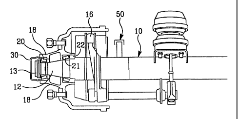
Referring now to FIGS. 3 and 4, the vent system of the present invention is
illustrated for
conventional use, for example, on a vehicle, such as a tractor or a trailer,
having wheels, which are
each rotatably connected to an end of an axle via bearings. The axle tube 10
and spindle 12 are
disposed along an axis of rotation'x-x'. A conventional brake spider 16 is
provided adjacent the axle
tube 10 and a hub assembly 18 is rotatably mounted on the spindle 12 via a
pair of wheel bearings 20,
21 disposed between the spindle 12 and the hub assembly 18. A spindle nut 13
is threadingly
disposed on the spindle end and the nut 13 serves to as a bearing adjuster for
applying a preload force
6
CA 02326615 2000-11-22
to the bearing 20. Lubricant is disposed adjacent the wheel bearings 20, 21
and a lubricant sea122
prevents loss of lubricant. A hubcap 30 mounts onto a wheel hub and functions
to contain lubricant
for lubricating the bearings during operation of the wheel, hub and bearings.
As will be described in
greater detail below, a check valve 50 is disposed along the axle tube 10 and
that check valve 50
vents the wheel end assembly through the filtered spindle plug assembly 40 to
atmospheric pressure.
In the manner shown in FIG. 4, a spindle plug assembly 40 is mounted or press-
fit to the end
of the hollow spindle 12 and the spindle plug assembly 40 serves to close the
end of the passageway
leading to the axle tube 10. As shown in FIG. 5a and 5b, the spindle plug
assembly 40 comprises a
cup-shaped spindle plug 42, a filter member 44, non-porous disk 47, and a clip
retainer 46. The
spindle plug 42 is formed with recess 42a defined by walls 42b as well as a
vent passage 42c. The
f lter member 44 is sized to fit within the recess 42a and cover the vent
passage 42c. The non-porous
disk 47 is formed with a center hole 47a for passage of air, and the non-
porous disk 47 keeps the
porous disk 44 from becoming oil-soaked. The clip retainer 46 is preferably
formed as a ring that
provides a snap fit connection to the cup-shaped spindle plug 42 to thereby
retainer the filter member
44 within the recessed portion 42a. The filtered spindle plug serves two
purposes; first to vent the
wheel hub cavity to atmosphere (via the axle tube vent) and, second, to
prevent contaminants from
entering the axle tube. The venting property avoids damage to the wheel seal
that might be caused
by excessive positive and/or negative pressure in the wheel hub cavity. In
addition, vented cap 40
prevents external contaminants such as grit and water from entering the wheel
hub cavity.
FIGS. 6a, 6b and 7 show alternate embodiments of the spindle plug assembly
designed to
protect the porous plastic member from oil contamination. The spindle plug
assemblies of FIGS. 6a,
6b and 7 are designed with a filter section of smaller diameter to limit
exposure of the filter member
7
CA 02326615 2000-11-22
to oil. FIGS. 6a and 6b show a spindle plug assembly 140 comprising a cup-
shaped spindle plug 142,
a filter member 144 and a spring-clip retainer 146. The spindle plug 142 is
formed with recess 142a
defined by walls 142b as well as a vent passage 142c. The filter member 144 is
sized to fit within
the recess 142a and cover the vent passage 142c. The clip retainer 146 is
preferably formed as a
resilient spring-like member that provides a snap fit connection to the cup-
shaped spindle plug 142
to thereby retainer the filter member 144 within the recessed portion 142a.
FIG. 7 shows a third spindle plug assembly 240 comprising a cup-shaped spindle
plug 242,
and a porous plug-shaped filter member 244. The spindle plug 242 is formed
with a central vent
passage 243. The plug-type filter member 244 is press-fit into the passage
243.
As shown in FIG. 3, significant to the vent system of the present invention is
the one-way,
check valve 501ocated on the axle tube 10 which vents the wheel end assembly
through the filtered
spindle plug assembly 40 to atmospheric pressure. Therefore, the vent system
of this invention is not
susceptible to fouling or contamination when, for example, the axle runs
through water. The hubcap
30 does not include a vent and is not otherwise altered to provide
communication between the wheel
end assembly and atmosphere. Instead, the wheel end assembly of this invention
is vented through
the spindle plug assembly 40 to atmosphere through the one-way check valve 50
disposed on the axle
tube 10. The exact height and position of the one-way check valve 50 is chosen
depending on the
environment of use of the vehicle. A vehicle that often runs through deep
water will require a check
valve 50 position relatively high above the axle. The iunportant feature of
this invention is the ability
to vent the wheel end assembly through a first, preferably filtered, vent 40
at the end of the axle tube
and then through a second vent 50 to atmosphere. To this end, a hose may
extend from the check
valve 50 to raise or adjust the effective height and position of the check
valve 50 in a convenient and
8
CA 02326615 2000-11-22
economical manner.
As previously discussed, it is common for moisture or condensation to enter
the axle tube 10.
The moisture or condensation may build up within the axle tube and cause
corrosion. In addition,
when the vehicle is on an incline, the accumulated water may exit the axle
tube and enter the wheel
end assembly. When this occurs, the water and moisture contacts the wheel
bearing assembly,
lubricant, and associated seals thereby causing damage.
The filter member 44 is preferably a flexible porous disk or sheet positioned
across the inner
surface of the recess 42a and covering the vent passage 42c. The porous sheet
44 includes pores or
interstices of a size sufficient to prevent the flow of fiquids, such as
lubricant and water, therethrough
while permitting the flow of gases therethrough. The porous sheet 44 is
oleophobic, and
correspondingly hydrophobic, and functions to contain the lubricarit within
chamber while allowing
air to pass to and from chamber through vent passage 46. To achieve this
function, the porous sheet
44 is preferably comprised of a non-metallic material, such as a porous
plastic member, or a porous
expanded membrane of polytetrafluoroethylene (PTFE) in the form of a disc
having a pore size in the
microporous size range. Such membranes have a pore size in the 0.045 micron
size range or smaller,
and maintain a watertight seal while permitting an enclosure to "breathe".
The enclosure device of the spindle cap 42 of the present invention
effectively shields the
porous venting sheet 44 from contaminants such as grit. The accumulation of
grit on the surface of
the porous sheet 44 could reduce its permeability thus impairing its ability
to vent the wheel hub
cavity while possibly requiring frequent replacement of the porous sheet 44.
Therefore, the enclosure
of the present invention is useful in extending the duration for which the
porous sheet 44 remains
permeable to air.
9
CA 02326615 2000-11-22
As can be seen from the foregoing, a vent system formed in accordance with the
present
invention will relieve pressure developed within the wheel hub cavity, by
venting, while preventing
water and other contaminants from entering the hubcap and contacting the wheel
bearings. This will
extend, effectively, the useful life of the lubricant and bearings. Moreover,
by forming the vent system
in accordance with the present invention, an enclosure is provided which is
useful in preventing grit
and other contaminants from accumulating on the surface of the venting
structure thereby maintaining
the air flow vent path and ensuring proper venting of the wheel end assembly.
Additionally, a vent
system formed in accordance with the present invention will enable materials
to be used for venting
which do not need to rely upon an interference fit within the vent passage
thereby resulting in a
simple, inexpensive yet effective vented wheel end assembly.
While the foregoing invention has been shown and described with reference to a
preferred
embodiment, it will be understood by those of skill in the art that various
changes in form and detail
may be made therein without departing from the spirit and scope of the present
invention.