Note: Descriptions are shown in the official language in which they were submitted.
CA 02326701 2000-11-21
SHIFT AND STEERING CONTROL SYSTEM
FOR WATER JET APPARATUS
FIELD OF THE INVENTION
This invention generally relates to water jet
apparatus for propelling boats and other watercraft. In
particular, the invention relates to mechanisms for
steering and/or shifting a water jet apparatus.
BACKGROUND OF THE INVENTION
It is known to propel a boat or other watercraft using
a water jet apparatus mounted to the hull, with the
powerhead being placed inside (inboard) the hull. The drive
shaft of the water jet apparatus is coupled to the output
shaft of the inboard motor. The impeller is mounted on the
drive shaft and housed in a jet propulsion pipe or water
tunnel.
To facilitate use of water jet-propelled boats in
shallow water, it is known to mount the water jet at an
elevation such that the water jet does not project below
the bottom of the boat hull. This can be accomplished, for
example, by installing a duct in the stern of the boat, the
duct being arranged to connect one or more inlet holes
formed in the bottom of the hull with an outlet hole formed
in the transom. The water jet is then installed outside the
hull in a position such that the water jet inlet is in flow
communication with the duct outlet at the transom. Such a
system is shown in Australian Patent Specification No.
262306, published in 1963. Alternatively, the water jet can
be installed inside the duct built into the hull, as shown
in U.S. Patent No. 5,181,868.
In another type of design, a water jet apparatus is
installed inside the hull and penetrates the transom. An
inlet housing of the water jet has a horizontal opening and
an inclined water tunnel for guiding water to the impeller.
1
CA 02326701 2000-11-21
The horizontal opening of the inlet housing is mounted in a
hole in the bottom or near the bottom of the hull. A
similar design is disclosed in Swiss Patent No. 481788.
The prior art cited above does not disclose means
for passing through the hull the control system for
shifting and steering the reverse gate and the steering
nozzle respectively of a water jet apparatus mounted to
the hull. In particular, there is a need for a design
which would allow the shift and steering control system
to penetrate a horizontal section of the hull.
SUN~IARY OF THE INVENTION
The present invention is a shift and steering control
assembly for activating the steering nozzle and reverse
gate of a water jet apparatus. The water jet apparatus
comprises an inlet housing which is mounted outside the
hull in a cavity. The control cables are located inside the
hull and activate the steering nozzle and reverse gate by
means of levers and links. The shift and steering control
assembly is designed for easy assembly. In particular, the
shift and steering control assembly comprises a modular
lever and shaft assembly which can be installed in the
inlet housing, before the inlet housing is installed in the
hull. When the inlet housing is installed, the modular
lever and shaft assembly penetrates the hull. To facilitate
passage of the upper portion of the lever and shaft
assembly through an opening in the hull, one of the upper
levers is not attached to the assembly until after the
inlet housing is attached to the hull. Then the shift and
steering cables are connected to upper shift and steering
levers respectively. In the final assembled state, the
shift and steering cables and upper shift and steering
levers are inside the hull, while the lower shift and
steering levers and the shift and steering rods reside
outside the hull.
2
CA 02326701 2000-11-21
In accordance with the preferred embodiment of the
invention, the modular lever and shaft assembly comprises a
shift and steering control housing which is mounted to the
inlet housing. The shift and steering control housing has
respective bores for housing shift and steering shafts.
Upper shift and steering levers are coupled to the upper
ends of the shift and steering shafts respectively, while
lower shift and steering levers are coupled to the lower
ends of the shift and steering shafts respectively, thus
forming rigid structures which are ratatably supported by
the shift and steering control housing. In response to
operation of one of the cables, the corresponding rigid
lever and shaft assembly is rotated, causing the respective
lower lever to swing, thereby displacing the corresponding
control rod. The steering nozzle is activated in response
to operation of the steering cable, while the reverse gate
is activated in response to operation of the shift cable.
BRIEF DESCRIPTION OF THE DRAWINGS
FIG. 1 is a schematic (presented in two sheets
respectively labeled FIGS. lA and 1B) showing a sectional
view of a water jet apparatus mounted to a boat hull in
accordance with a preferred embodiment of the invention,
the section being taken along a vertical midplane.
FIG. 2 is a schematic (presented in two sheets
respectively labeled FIGS. 2A and 2B) showing a top view of
the top mounting plate and the water jet apparatus depicted
in FIG. 1, with the hull removed.
FIG. 3 is a schematic showing a top view of the inlet
housing in accordance with the preferred embodiment of the
invention.
FIGS. 4, 6 and 7 are schematics showing top, side and
bottom views of the shift and steering control housing in
accordance with the preferred embodiment of the invention.
3
CA 02326701 2000-11-21
FIG. 5 is a schematic showing a sectional view taken
along line 5-5 shown in FIG. 2A.
FIG. 8 is a schematic showing a side view of the upper
steering lever in accordance with the preferred embodiment
of the invention.
FIG. 9 is a schematic showing a sectional view of the
upper steering lever, the section being taken along line 9-
9 shown in FIG. 8.
DETAILED DESCRIPTION OF THE PREFERRED EMBODIMENTS
As seen in FIG. 1, the water jet apparatus
incorporating the invention is designed to be installed in
a cavity under a section of the hull and in flow
communication with the outlet of an inlet ramp built into
the hull. As seen in FIG. 1, the boat hull 2 has an inlet
ramp 6 formed by a pair of opposing sidewalls 8 and a guide
surface 10 which curves gently upward in the aft direction.
The end of the inlet ramp 6 is in flow communication with
a cavity in which the water jet apparatus is installed.
This cavity for the water jet apparatus is defined by a
horizontal hull section 12, a vertical hull section 14
and a pair of opposing sidewalls 16 (only one of which is
visible in FIG. 1), the cavity being open at the bottom
and rear for allowing insertion of the water jet
apparatus.
The water jet apparatus comprises an inlet housing
18 which is slid into the aforementioned cavity and
bolted to the hull by means of a top mounting plate 20
and a front plate 22. At the time of inlet housing
installation, the drive shaft 26 is already rotatably
mounted in the inlet housing. In particular, the inlet
housing 18 comprises a vertical strut 85 having an axial
bore which houses a portion of the drive shaft.
4
CA 02326701 2000-11-21
During inlet housing installation, the front plate 22 is
placed on the inside of the vertical hull section 14 and
the inlet housing 18 is placed on the outside of vertical
hull section 14, a set of three throughholes in the
vertical hull section 14 and a set of three threaded
holes in the inlet housing 18 being aligned with a set of
three throughholes in the vertical hull section 14. Three
screws 24 (only one of which is visible in FIG. 1) are
passed through the aligned throughholes and screwed into
the threaded holes of the inlet housing 18. The numeral
25 in FIG. 1 denotes a washer placed between the head of
screw 24 and the front plate 22. The front plate 22 has
an opening 34 (best seen in FIG. 2) which, in the
assembled state, is aligned with an opening 36 in the
vertical hull section 14 to allow the output shaft (not
shown) from the inboard motor to be coupled to the front
end of the drive shaft 26. The studs 28 are affixed to
the inlet housing 18. The inlet housing 18 is inserted
into the hull cavity and the studs 28 are inserted into
throughholes in the hull. The front plate 22 is then
positioned and screws 24 are screwed into the inlet
housing 18. The top mounting plate 20 is then placed over
the studs 28 and secured to the hull using nuts and
washers.
In the assembled position, a front portion of the
inlet housing 18 is sealed against the vertical hull
section 14 by means of a seal 30 and a top portion of the
inlet housing 18 is sealed against the horizontal hull
section 12 by means of a seal 32. The seal 30 encompasses
the interface where the openings in the vertical hull
section 14 and inlet housing for the drive shaft 26 meet
and is designed to prevent water leaking into the drive
shaft assembly or into the boat via the opening 36.
Similarly, the top mounting plate 20 has an opening 38
which, in the assembled state, is aligned with an opening
in the horizontal hull section 12 to allow a shift and
5
CA 02326701 2000-11-21
steering control housing 42 to be placed in a corre-
sponding opening in the top wall of the inlet housing 18.
The seal 32 encompasses the interface where the openings
in the horizontal hull section 12 and inlet housing for
the shift and steering housing 42 meet and is designed to
prevent water leaking into the boat via the opening 38.
In addition, a seal 31 is pressed between the inlet
housing 18 and the hull along the front and sides of the
inlet housing.
The inlet housing 18 has a water tunnel 44 with an
inlet 46. The water tunnel 44 has a pair of sidewalls 48
(only one of which is shown in FIG. 1) which are
generally coplanar with the sidewalls 8 of the hull inlet
ramp 6. In addition, the water tunnel 44 has a guide
surface 50 which starts at a point near where the guide
surface 10 of the hull inlet ramp 6 ends and then curves
gradually upward in the aft direction. As a result of the
foregoing structure, there is a generally smooth
transition between the end of inlet ramp 6 and the
beginning of water tunnel 44. Thus the hull 2 and the
inlet housing 18 combine to form a single inlet for
guiding water toward the inlet of a stator housing 52
located downstream of the inlet housing.
An inlet grate 54 extends across the inlet 46 of the
water tunnel 44 and serves to block the admission of
debris into the water jet apparatus. The inlet grate 54
comprises a multiplicity of generally parallel tines 56
which extend downward and rearward from an upper end of
the inlet grate. Only the upper end of the inlet grate is
attached to the inlet housing by screws (not shown). The
cantilevered design is based on the theory that any weeds
that wrap around the grate will be drawn down to the
lower, open end and slide off under the boat and/or be
drawn into the pump and chopped up. In addition, a ride
plate 58 is attached to the bottom of the inlet housing
6
CA 02326701 2000-11-21
18.
As shown in FIG. 1, the drive shaft projects in the
aft direction out of the inlet housing 18. The impeller
is pre-assembled in the unit prior to mounting in the
hull. The hub and blades of impeller 60 are integrally
formed as one cast piece. The hub of impeller 60 has a
splined bore which meshes with splines formed on the
external surface of the drive shaft 26, so that the
impeller 60 will rotate in unison with the drive shaft
26. Also, a taper on the impeller locks on to a taper on
the drive shaft to hold the impeller in place (see FIG.
3). The impeller 60 is held securely on the drive shaft
26 by a washer 62, which in turn is held in place by a
lock nut 64 tightened onto a threaded end of the drive
shaft 26. As seen in FIG. 1, the hub of the impeller 60
increases in radius in the aft direction, transitioning
gradually from a generally conical outer surface at the
leading edge of the impeller hub to a generally circular
cylindrical outer surface at the trailing edge of the
impeller hub. This outer surface of the impeller hub
forms the radially inner boundary for guiding the flow of
water impelled by the impeller.
The stator housing 52 comprises inner and outer
shells connected by a plurality of stator vanes, all
integrally formed as a single cast piece. The hub of the
stator housing 52 gradually decreases in radius in the
aft direction, starting out at a radius slightly less
than the radius at the trailing edge of the impeller hub.
The stator vanes are designed to redirect the swirling
flow out of the impeller 60 into non-swirling flow. The
stator housing hub has a radial end face with a central
throughhole. Before the stator housing is installed, a
tail cone cover 66 is attached to the radial end face of
the stator housing hub by a screw 68. The front of the
stator housing 52 is then attached to the rear of the
7
CA 02326701 2000-11-21
inlet housing 18 by a plurality of screws (not shown in
FIG. 1) .
A circumferential recess in the stator housing 52 at a
position opposing the impeller blade tips has a circular
cylindrical wear ring 65 seated therein. Wear to the
impeller blade tips is mainly due to the pumping of
abrasives such as beach sand. The purpose of the wear ring
65 is to protect the soft aluminum casting with a hard
stainless steel surface, thus drastically reducing the rate
of wear .
After the stator housing 52 (with attached tail cone
cover 66) has been attached to the inlet housing 18, the
front of an exit nozzle 70 is attached to the rear of the
stator housing 52 by screws. The front faces of the tail
cone cover 66 and the exit nozzle 70 are preferably
coplanar. The water flowing out of the stator housing 52
will flow through the space between the tail cone cover 66
and the exit nozzle 70, and then will exit the exit nozzle
at its outlet.
The water jet apparatus shown in FIG. 1 is provided
with a steering nozzle 72 which can change the direction of
the water exiting the exit nozzle 70. This effect is used
by the boat operator to steer the boat left or right. To
accomplish this, the steering nozzle 72 is pivotably
mounted to the exit nozzle 70 by a pair of pivot assemblies
located at the top and bottom of the exit nozzle. Each
pivot assembly comprises a screw 74, a sleeve (not visible
in FIG. 1) and a bushing 76. The axes of the screws 74 are
collinear and form a vertical pivot axis about which the
steering nozzle 72 can rotate. In particular, the steering
nozzle has a pair of circular holes in which the bushings
76 are seated. The sleeves are inserted inside the
respective bushings 76. The screws 74 are in turn inserted
in the sleeves and screwed into respective threaded holes
in the exit nozzle 70. As best seen in FIG. 2B, the
8
CA 02326701 2000-11-21
steering nozzle 72 has an arm 73 which is pivotably coupled
to a flattened end of a steering rod 114. Displacement of
the steering rod 114 in response to operation of a steering
cable 78 (see FIG. 2A) causes the steering nozzle to swing
a desired direction about its vertical pivot axis.
The water jet apparatus shown in FIG. 1 is also
provided with a non-steerable reverse gate 80 which is
pivotable between forward and reverse positions. In the
forward position, the reverse gate 80 is raised, thereby
allowing water to exit the steering nozzle 72 freely. In
the reverse position, the reverse gate 80 is lowered to a
position directly opposite to the outlet of the steering
nozzle 72. The reverse gate is designed to partially
reverse the flow of water exiting the steering nozzle 72
when the reverse gate is in the reverse position. This
reverse flow of water will urge the boat in the aft
direction. To accomplish the foregoing, the reverse gate 80
is pivotably mounted to the exit nozzle 70 by a pair of
pivot assemblies 94 and 96 located on opposite sides of the
exit nozzle (see FIG. 2B). Each pivot assembly 94 and 96
has a construction substantially identical to the pivot
assemblies previously described with reference to pivoting
of the steering nozzle 72. As seen in FIG. 2B, the reverse
gate has a pair of arms 98 and 100, the ends of which are
pivotably coupled to the respective pivot assemblies 94,
96. The reverse gate 80 is pivoted by a shift rod 92, the
end of which is coupled to arm 98 of the reverse gate 80 by
means of a rod end assembly 102 which comprises a ball
socket for allowing horizontal radial motion at the shift
lever and vertical radial motion at the reverse gate. The
rod end assembly is attached to arm 98 by means of a screw
104 and a lock nut 106. Displacement of the shift rod 92 in
response to operation of a shift cable 82 (see FIG. 2A)
causes the reverse gate to swing in a desired direction,
namely, into forward position or reverse position. The
reverse gate has a design which allows the boat to steer in
9
CA 02326701 2000-11-21
reverse in the same direction like an outboard, stern drive
or car.
In accordance with the preferred embodiment of the
invention, the shift and steering cables located inside the
hull are respectively coupled to the shift and steering
rods located outside the hull by means of respective lever
and shaft assemblies rotatably supported in a shift and
steering control housing 42 which is installed in a
corresponding opening in the top of the inlet housing 18.
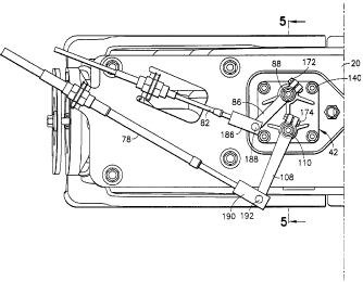
As best seen in FIGS. 4 and 5, the housing 42 preferably
comprises a base plate 116, an upper vertical tubular
structure 118 integrally formed with base plate 116 and
extending above it to a first height, and an upper vertical
tubular structure 120 integrally formed with base plate 116
and extending above it to a second height greater than the
first height. As seen in FIG. 5, the tubular structures 118
and 120 are reinforced by a rib 122 extending therebetween
and integrally formed therewith and with the base plate
116. Additional reinforcement is provided by respective
2 0 pairs of ribs 12 4 and 12 6 ( see FIG . 4 ) . As seen in FIG . 4 ,
the base of housing 42 has a generally square shape with
rounded corners. Below the base plate, the housing has a
circular cylindrical lower wall 128 (shown in FIG. 7),
integrally formed with lower vertical. tubular structures
130 and 132. The lower wall 128 slides into a circular
opening 134 (shown in FIG. 3) formed in the top wall of the
inlet housing 18. The opening 134 in the inlet housing
communicates with the exterior of the water jet apparatus
via a pair of opposing side channels through which the
lower shift and steering levers (described below)
respectively pass. The lower wall 128 is provided with a
pair of annular grooves 136 (see FIG. 6) in which
respective O-rings 138 (see FIG. 5) are installed to seal
the interface of the respective housings 18 and 42 against
leakage of water through opening 134 and into the hull.
CA 02326701 2000-11-21
Preferably the opening 40 (see FIG. lA) in the
horizontal hull section 12 closely matches the opening in
mounting plate. As seen in FIG. 2A, the housing 42 is
bolted to the inlet housing 18 by studs 140. The shift and
steering control housing 42 has throughholes 142 at
respective corners (see FIGS. 4 and 7). The studs 140 are
threaded into respective threaded holes 144 formed in the
top wall of the inlet housing 18 (see FIG. 3).
As seen in FIG. 5, the shift and steering control
housing 42 has one bore 146 for receiving the shift shaft
88 and another bore 148 for receiving' the steering shaft
110. The bore 146 has upper and lower annular recesses in
which upper and lower bushings 150 and 152 are respectively
inserted; the bore 148 has upper and lower annular recesses
in which upper and lower bushings 154 and 156 are
respectively inserted. The shift shaft 88 is rotatably
supported in bushings 150 and 152, while steering shaft 110
is rotatably supported in bushings 154 and 156. One end of
the upper shift lever 86 is secured to the top of the shift
shaft 88 by means of a lock nut 158 which screws onto a
threaded end of the shift shaft; one end of the upper
steering lever 108 is secured to the top of the steering
shaft 110 by means of a lock nut 160 which screws onto a
threaded end of the steering shaft. (Only a portion of each
of the upper levers is shown in FIG. 5.) The upper levers
bear on the flanges of the upper bushings during rotation
of the lever and shaft assemblies.
As shown in FIG. 9, the upper shift lever 86 has a D-
slot 162 which form fits on a portion of the shift shaft
having a D-shaped cross section. As seen in FIG. 8, the
upper shift lever 86 has a pair of opposing fingers 164 and
166, the former having a threaded hole 168 and the latter
having a throughhole 170. These fingers are pinched
together by a screw 172, best seen in FIG. 2A, the
resulting compressive force clamping the upper shift lever
11
CA 02326701 2000-11-21
to the shift shaft. The upper steering lever 108 has a
similar construction, with fingers pinched together by a
screw 174 to clamp the upper steering lever to the steering
shaft. Alternatively, the shift and steering levers can be
stampings retained by washers and nuts, with the "pinch"
fingers being eliminated. The reference numeral 176
designates a pair of seals installed in annular recesses
formed at the bottom of the respective lower vertical
tubular structures 130 and 132, in surrounding relationship
with the shift and steering shafts respectively.
Still referring to FIG. 5, a lower shift lever 90 is
welded to the bottom of the shift shaft 88, while a lower
steering lever 112 is welded to the bottom of the steering
shaft 110. A lower washer 178 is installed between the
lower shift lever 90 and the lower vertical tubular
structure 130 of the shift and steering control housing 42,
while a lower washer 180 is installed between the lower
steering lever 112 and the lower vertical tubular structure
132 of housing 42. The washers 178 and 180 provide a
bearing surface.
The full length of the lower steering lever 112 is
shown in FIG. 5, while only a portion of the lower shift
lever 90 is depicted. FIG. 5 shows a clevis 182 and a
shoulder screw 184 for attaching the distal end of the
lower steering lever 112 to the forward end of the steering
rod (not shown in FIG. 5). Similarly, the distal end of the
lower shift lever is attached to the forward end of the
shift rod by means of a clevis and shoulder screw coupling
(not shown in FIG. 5).
Referring to FIG. 2A, the distal end of the upper
shift lever 86 is attached to the shift cable 82 by means
of a clevis 186 and a clevis pin 188. These components are
located inside the hull of the boat (see FIG. lA). Dis-
placement of the end of the shift cable causes the shift
lever and shaft assembly to rotate. Likewise the distal end
12
CA 02326701 2000-11-21
of the upper steering lever 108 is attached to the steering
cable 78 by means of a clevis 190 and a clevis pin 192, and
displacement of the end of the steering cable causes the
steering lever and shaft assembly to rotate. As best seen
in FIG. lA, the shift cable 82 is supported by a bracket
194 and the steering cable 78 is supported by a bracket
196, both brackets being integrally connected to and
extending vertically upward from the top mounting plate 20.
In response to operation of the steering cable 78, the
steering nozzle can be selectively turned left or right to
steer the boat as desired during water jet operation. In
response to operation of the shift cable 82, the reverse
gate can be selectively raised or lowered to propel the
boat forward or rearward as desired during water jet
operation.
The foregoing structure is designed to facilitate
installation of a shift and steering control system which
penetrates a horizontal hull section of a boat. The
assembly procedure is as follows. The lower levers are
welded to the bottom ends of the respective shift and
steering shafts. These welded lever and shaft subassemblies
are then inserted in a large opening in the inlet housing,
the bottoms of the shafts being supported by a boss 198
(seen in FIG. 5). As part of the assembly, grease is
applied to both shafts. Then a pair of O-rings are in-
stalled in the annular grooves of the shift and steering
control housing 42. One of the shaft is then placed in
position in the opening in the inlet housing and the
corresponding bore (146 or 148) of the shift and steering
control housing 42 is slid over the top part of that shaft.
Then the second shaft is passed up through the inlet
housing and its top section is slid into the other bore,
following which the housing 42 is slid downward and into
the receiving opening in the inlet housing 18. In the final
position, the housing 42 is bolted to the inlet housing 18.
Then the upper shift lever 86 is assembled to the shift
13
CA 02326701 2000-11-21
shaft 88. The upper steering lever is not pre-assembled to
its shaft to allow assembly of the inlet housing to the
hull. Therefore, means are provided for retaining the
steering shaft and lower steering lever subassembly in the
housing 42, either temporarily or permanently, until the
upper steering lever is installed in the boat. After the
inlet housing has been attached to the hull via the front
plate and top mounting plate, the upper steering lever is
attached to the top of the steering shaft. Then the shift
and steering cables are respectively connected to the upper
shift and steering levers.
Preferably the inlet housing and the shift and
steering control housing are made of sand-cast aluminum or
molded plastic, while the stator housing is preferably made
of stainless steel.
While the invention has been described with reference
to preferred embodiments, it will be understood by those
skilled in the art that various changes may be made and
equivalents may be substituted for elements thereof without
departing from the scope of the invention. In addition,
many modifications may be made to adapt a particular
situation to the teachings of the invention without
departing from the essential scope thereof. Therefore it is
intended that the invention not be limited to the
particular embodiment disclosed as the best mode contem-
plated for carrying out this invention, but that the
invention will include all embodiments falling within the
scope of the appended claims.
As used in the claims, the term "outlet housing"
comprises one or more attached parts. For example, in the
disclosed preferred embodiment, the stator housing and the
exit nozzle form an outlet housing. However, the present
invention encompasses forming the stator housing and the
exit nozzle as one piece, or forming the stator housing as
two pieces, and so forth.
14