Note: Descriptions are shown in the official language in which they were submitted.
CA 02326919 2000-11-21
PROSTHETIC IMPLANT ELEMENT
FIELD OF THE INVENTION
The present invention relates to medical devices, and particularly to
prosthetic
implant components, and more particularly to an implantable artificial spinal
disc.
BACKGROUND OF THE INVENTION
Advancing age, as well as injuries, can lead to changes in the various bones,
discs, joints, and ligaments of the body. Such changes and injuries often
manifest
themselves in the form of damage or degeneration of a spinal disc, the result
of which
is mild to severe chronic back pain. Under certain circumstances, this pain
can be
lessened or completely alleviated by removal of the damaged or degenerated
spinal
disc, followed by the implantation of an artificial intervertebral disc.
Many artificial intervertebral discs are known, such as those disclosed in
U.S.
Patent Nos. 5,893,889 to Harrington, 5,683,465 to Shinn et al.5,674,294 to
Bainville et
al., 5,458,643 to Oka et al., 5,306,309 to Wagner et al., 5,246,458 to Graham,
and
4,759,769 to Hedman. There remains a need, however, to substantially simulate
a
healthy spinal disc, while still allowing for ease of insertion and/or removal
of the
prosthetic device, and while providing adequate protection against expulsion
of the
implanted prosthetic disc. Thus, it remains a goal in the art to produce a
prosthetic
device, such as an artificial intervertebral disc, that possesses these
properties.
-1-
CA 02326919 2006-07-27
SUMMARY OF THE INVENTION
The present invention provides an implantable prosthetic element. Although the
invention is primarily shown and described as an artificial disc prosthesis,
it is
understood that the invention has other applications as well, such as for use
as an ankle
or heel prosthesis.
The implantable prosthetic element has a first end plate and a second end
plate,
each of which has a bone-facing surface and an opposed mating surface. The
bone-
facing surfaces of the first end plate and the second end plate each have a
plurality of,
lobes protruding therefrom. A core is interposed between and attached to
the mating surfaces of the first end plate and the second end plate. The
prosthetic
element is constructed such that the thickness is greater at the anterior side
than at the
posterior side. As a result, the lobe surface is generally oriented at an
angle, sloping
from the anterior to the posterior side_
Some or all of the plurality of lobes include one or more wedge-like fins
which
protrude therefrom. The lobes may also include a plurality of surface features
that
promote osteo-integration.
In one embodiment of the present invention, the first end plate and the second
end plate each contain two lobes, with a slot separating the two lobes of each
end plate.
Each slot may optionally include one or more recesses to facilitate insertion
and/or
extraction of the element from its implantation site.
BRIEF DESCRIPTION OF THE DRAWINGS
The invention will be more fully understood from the following detailed
description taken in conjunction with the accompanying drawings, in which:
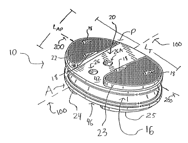
FIG. 1 is a perspective view of an implantable prosthetic element in
accordance
with the present invention;
FIG. 1A is a top, plan view of a wedge-like fin of the element of FIG. 1;
FIG. 1B is a perspective view of a wedge-like fin of the element of FIG. 1;
FIG. 1C is a side view of a wedge-like fin of the element of FIG. 1C;
-2-
CA 02326919 2000-11-21
FIG. 2 is a side, elevational view of the implantable prosthetic element of
FIG.
1;
FIG. 3 is a plan view of the bone-facing surface of the first end plate of the
implantable prosthetic element of FIG. 1;
FIG. 3A is a plan view of an alternate embodiment of the bone-facing surface
of
the first end plate of the implantable prosthetic element of FIG. 1;
FIG. 3B is a plan view of another embodiment of the bone-facing surface of the
first end plate of the implantable prosthetic element of FIG. 1;
FIG. 4 is a front, elevational view of the implantable prosthetic element of
FIG.
1;
FIG. 5 is a plan view of the bone-facing surface of the second end plate of
the
implantable prosthetic element of FIG. 1;
FIG. 5A is a plan view of an alternate embodiment of the bone-facing surface
of
the second end plate of the implantable prosthetic element of FIG. 1;
FIG. 6 is a front, elevational view of the implantable prosthetic element of
FIG.
1;
FIG. 7 is a sectional view along line 7-7 of the implantable prosthetic
element of
FIG. 4;
FIG. 8 is a sectional view along line 8-8 of the implantable prosthetic
element of
FIG. 3;
FIG. 8A is a sectional view along line 8A-8A of FIG. 8;
FIG. 9 is a sectional view along line 9-9 of the implantable prosthetic
element of
FIG. 5;
FIG. 9A is a sectional view along line 9A-9A of FIG. 9;
FIG. 10 is a schematic view of the implantable prosthetic element of FIG. 1
immediately prior to its insertion between spinal vertebrae; and
FIG. 11 is a schematic view of the implantable prosthetic element of FIG. 1
following its insertion between spinal vertebrae.
DETAILED DESCRIPTION OF THE DRAWINGS
Referring initially to FIGS. 1, lA, 113, 2, 3, 4 and 5, an implantable
prosthetic
element 10 is shown. The element 10 has a first end plate 12 and a second end
plate
-3-
CA 02326919 2000-11-21
14. The first end plate 12 has a bone-facing surface 42 and an opposed mating
surface
44, and the second end plate 14 has a bone-facing surface 46 and an opposed
mating
surface 48. An elastomeric core 16 is interposed between and attached to the
mating
surfaces 44, 46 of the first and second end plates 12, 14.
The first and second end plates 12, 14 include bone-facing surfaces 42, 46. As
shown in FIGS. 1 and 2-4, the bone facing surface 42 of the first end plate 12
includes
adjacent lobes 22, 23 separated by at least one slot 20. The slot 20 may
include one or
more extraction recesses 26, formed as blind bores in the slot surface. A
further
surface feature 26A may also be formed on the surface of slot 20 of the bone-
facing
surface 42 of the first end plate 12, serving as a visual key to indicate the
top or
superior surface of element 10. Surface feature 26A may be in the form of a
recess or a
protrusion. Similarly, as shown in FIGS. 5-7, the second end plate 14 has a
bone-
facing surface 46 with adjacent lobes 24, 25 that are separated by a slot 21.
Either or
both of the bone-facing surfaces 42, 46 of the first end plate 12 and the
second end plate
14 of the element 10 can include one or more bone-penetrating, wedge-like fins
18
protruding therefrom.
One of ordinary skill in the art will appreciate that bone-facing surfaces 42,
46
may include only a single lobe, or more than two lobes. If only a single lobe
is present,
there need not be a slot. If more than two lobes are present, more than one
slot may
exist.
In the illustrated embodiment, each lobe 22, 23, 24, 25 is elevated above the
surfaces of slots 20, 21. FIGS. 2 and 7 illustrate that the dimensions and
geometry of
the end plates 12, 14 and the lobes 22, 23, 24, 25 cause the overall thickness
(T) of the
element 10 to taper from the anterior face (A) to the posterior face (P) at an
angle in the
range of about 2 to 35 , and more preferably about 5 to 15 . Thus, the
thickness (T)
of the element 10 is greatest when measured between the anterior portions of
the lobes,
and least when measured between the posterior portions of the lobes. The
thickness T
of element 10 at the anterior side is in the range of about 5 to 21 mm, while
the
thickness T at the posterior side is in the range of about 1 mm to 15 nun.
-4-
CA 02326919 2000-11-21
Element 10 has an anterior side (A) and a posterior side (P), with an anterior-
posterior (A-P) axis 100 extending therebetween. A transverse axis 200 extends
through element 10 perpendicular to the A-P axis 100. As shown in FIGS. 1, 2,
4, 6
and 7, each of the first and second bone-facing surfaces 42, 46 includes a
peripheral
flange 54, 56 which extends beyond the perimeter of the lobes 22, 23, 24, 25.
As
shown in the top plan views of FIGS. 3, 3A, 3B, 5 and 5A, the peripheral
flanges 54,
56 of the bone-facing surfaces 42, 46 are similarly sized and shaped.
As noted above, element 10 may contain bone-penetrating, wedge-like fins 18 to
enhance secure implantation of the element 10 at the desired location, and to
prevent the
expulsion of the element from its implantation location. The fins 18 may vary
in shape,
number, and in their placement on either of both of the end plates 12, 14.
As illustrated, exemplary fins 18 are elongated, with a length (L) that
extends
from a leading end 17 of each fin to a trailing end 19 of each fin such that
the length of
each fin is greater than a width (W) of each fin. Each fin 18 also has a
height (H) that
increases from the leading end 17 of the fin to the trailing end 19 of each
fin. In one
embodiment, the height Hf of each fin 18 is in the range of about 0.1 mm to
5.0 nun,
and more preferably in the range of about 1.0 mm to 2.0 mm. at the trailing
end 19 of
the fin. Generally, the length Lf of each fin is in the range of about 1 mm to
30 mm,
and more preferably about 3 mm to 9 mm, and the width Wf of each fin, at its
widest
point, is in the range of about 1 mm to 4 mm.
Due to the increasing height of each fin from leading end 17 to trailing end
19,
the crest 36 of each fin extends from the leading end 17 of the fin to the
trailing end 19
of the fin at an angle of extension (a). The angle of extension a may be in
the range of
about 5 to 85 with respect to a horizontal reference (H).
As shown in FIGS. 1 and 1A-iC, each fin 18 may have a substantially triangular
profile, with supporting legs 38, 40 that form first and second bone-
contacting surfaces
30, 32 that diverge from the crest 36. The supporting legs 38, 40 extend from
the crest
-5-
CA 02326919 2000-11-21
36 to the bone-facing, superior surface 42, 46 of an end plate 12, 14 at an
angle (0) in
the range of about 5 to 85 from a vertical reference (V) as shown in FIG.
1C.
In one embodiment, the trailing end 19 of each fin 18 includes an end face 34
that extends from the crest 36 to the bone-facing surface 42, 46 of end plates
12, 14.
Preferably, the end face 34 is generally anterior-facing. The end face 34 is
shown in
FIG. 1B as being substantially perpendicular to a horizontal reference (H) and
substantially parallel to a vertical reference (V). End face 34, however, may
also be
non-parallel to the vertical reference (V), such as, for example, undercut or
overcut
with respect to the vertical reference (V) as shown by dashed lines in FIG.
IC.
Although fins 18 are described and illustrated as having a substantially wedge-
like shape with a triangular profile, one of ordinary skill in the art will
appreciate that
other shapes may be used as well. It is also understood that the dimensions,
i.e.,
height, length, and width of the fins may vary, as may the overall geometry of
the fins.
With respect to the number of fins 18, there should generally be at least one
fin
protruding from each of the bone-facing surface 42 of the first end plate 12
and the
bone-facing surface 46 of the second end plate 14. Preferably, the number of
fins on
each of the bone-facing surface 42 of the first end plate 12 and the bone-
facing surface
of the second end plate 14 is identical. In exemplary embodiments of the
present
invention, the number of fins protruding from each bone-facing surface 42, 46
is four
(see FIGS. 3 and 5) and six (see FIGS. 3A, 3B and 5A). One of ordinary skill
in the
art, however, will understand that the number of fins 18 protruding from each
bone-
facing surface 42, 46 need not be identical. And, the number of fins 18
protruding
from each bone-facing, superior surface 42, 46 may be greater than six or less
than
four.
Each fin 18 should be arranged on bone-facing surfaces 42, 46 such that the
crests 36 of each fin are substantially parallel to each other. In one
embodiment, shown
in FIGS. 3, 3A, 5 and 5A, the fins 18 are arranged such that crests 36 are
substantially
parallel to the anterior-posterior axis 100 of the element. In other
embodiments, for
-6-
CA 02326919 2000-11-21
example FIG. 3B, the fins 18 may be oriented such that crests 36 extend at an
angle
with respect to the anterior-posterior (A-P) axis 100. One of ordinary skill
in the art
will readily appreciate that the fins 18 should be oriented so that the crests
36 are
parallel with the desired angle of insertion to be used by a surgeon during
surgical
installation of element 10. For example, if element 10 is to be used as an
artificial
intervertebral disc, the crests 36 of the fins 18 will be parallel to the A-P
axis 100 if an
anterior surgical approach is to be used. Alternatively, the crests 36 of the
fins will be
angled as shown in FIG. 3B if an anterior-lateral approach is to be used. One
of
ordinary skill in the art can readily determine an appropriate angular
orientation of fins
18.
The fins 18 may be arranged on the bone-facing surfaces 42, 46 in a variety of
patterns, which will be readily apparent to one of ordinary skill in the art.
Exemplary
patterns are illustrated in FIGS. 1, 3, 3A, 3B, 5 and 5A.
One of ordinary skill in the art will appreciate that although fins 18 exist
in a
currently preferred embodiment of the invention, an implantable prosthetic
element may
be constructed without fins.
As shown in FIGS. 1, 2, 4, 6 and 7, the elastomeric core 16 is interposed
between and attached to the first end plate 12 and the second end plate 14 as
disclosed
in U.S. Patent No. 5,824,094 to Serhan, which is expressly incorporated by
reference
herein. The core 16 has a superior core surface 50, an inferior core surface
52 and a
central peripheral portion 58.
As noted above, peripheral flanges 54, 56 form the perimeter or widest
portions
of the first and second end plates 12, 14. The perimeter of the core
peripheral portion
58 is generally about equal to the perimeter of the first and second
peripheral flanged
portions 54, 56 at the superior and inferior core surfaces 50, 52. However,
the core 16
is preferably sub-flush with respect to the end plates 12, 14 such that the
perimeter of
the core peripheral portion 58 tapers inward to a center portion from both the
superior
core surface 50 and the inferior core surface 52. Thus, the perimeter of the
central
-7-
CA 02326919 2000-11-21
peripheral portion 58 of core 16 is generally less than the perimeter of the
superior and
inferior core surfaces 50, 52 of core by an amount in the range of about 0.1
nun to
4 mm. One of ordinary skill in the art will understand, however, that
alternate
geometries may be utilized as well. For example, the peripheral flanges 54, 56
may be
different sizes, and the perimeter of the core 16 need not be sub-flush with
respect to
end plates 12, 14.
The lobes 22, 23, 24, 25 may have various shapes and dimensions in accordance
with the present invention. Each lobe has an anterior portion, a posterior
portion and
first and second side portions. As shown in FIG. 3, lobe 22 has an anterior
portion 60,
a posterior portion 62, a first side portion 64, and a second side portion 66,
while lobe
23 has an anterior portion 70, a posterior portion 72, a first side portion
74, and a
second side portion 76. As shown in FIG. 5, lobe 24 has an anterior portion
80, a
posterior portion, 82, a first side portion 84, and a second side portion 86,
while lobe
23 has an anterior portion 90, a posterior portion 92, a first side portion
94, and a
second side portion 96.
Lobes 22, 23, 24, 25 have heights that are defined as the distance each lobe
protrudes from the surface of slots 20, 21 of end plates 12, 14. In an
exemplary
embodiment of the present invention, the orientation of the bone-facing
surfaces 42, 46,
which are generally angled from the anterior side to the posterior side with
respect to
horizontal, has the effect that the height of each of lobes 22, 23, 24, 25
decreases from
their anterior portions 60, 70, 80, 90 to their posterior portions 62, 72, 82,
92. In
general, the height of each lobe 22, 23, 24, 25 is in the range of about 1 mm
to 6 nun at
the anterior side to about 0.1 mm to 1.0 nun at the posterior side
In an exemplary embodiment of the present invention, each of lobes 22, 23, 24,
25 is coated, plated or otherwise treated as is generally known in the art to
provide a
surface with features that promote osteo-integration. The osteo-integration
enhancing
surface features may be provided by, for example, applying a porous or beaded
coating
of a biocompatible material (e.g., titanium), a mesh layer, or a hydroxy
apatite coating.
One of ordinary skill in the art will appreciate that all or part of lobes 22,
23, 24, 25
-8-
CA 02326919 2000-11-21
may be treated to provide osteo-integration. It is also understood that
portions of the
bone-facing surfaces 42, 46, in addition to or in lieu of the lobes, may be
treated to
provide osteo-integration enhancing surface features.
As noted above, the slots 20, 21 represent unlobed areas of the bone-facing
surfaces 42, 46 of the end plates 12, 14. In one embodiment, the widths (W1,
W2) of
slots 20, 21 may be substantially constant along the entire anterior-posterior
length
(LAP) of the element 10. The widths (W1, W2) should be sufficient to enable an
installation tool (not shown) to grasp the element 10, and position the
element in its
implantation site. The widths (W 1, W2) of slots 20, 21 generally are equal.
In FIGS. 1, 3, 5 and 5A widths W1 And W2 are shown as being identical and
substantially constant and oriented to be parallel to the anterior-posterior
axis 100 of the
element 10. This design is preferred when the element 10 is to be inserted via
an
anterior approach. Alternatively, the slots 20, 21 may be configured in other
ways to
accommodate an anterior-lateral insertion technique. For example, the width
(WI, W2)
of slots 20, 21 can increase from the anterior side to the posterior side, or
from the
posterior side to the anterior side, as shown in FIG. 3B by dashed lines. FIG.
5A
illustrates another alternative in which the slots 20, 21 (shown by dashed
lines) are
widest at the anterior side and narrowest at the posterior side of the element
10. In
either embodiment, the width (Wi, W2) is generally in the range of about 4 mm
to 14
mm.
FIGS. 8, 8A, 9, and 9A further illustrate the geometry of lobes 22, 23, 24,
and
25. As noted above, the bone-facing surfaces 42, 46 of end plates 12, 14 are
substantially angled, sloping from the anterior to the posterior sides of the
element 10.
In addition to being mounted upon this canted surface of the end plates 12,
14, the lobes
22, 23, 24, and 25 each have substantially dome-like profiles, causing them to
be
curved in both the sagittal and coronal planes.
FIGS. 4, 6, 8A and 9A illustrate the radius of curvature in the coronal plane
of
lobes 22, 23, 24, and 25 of end plates 12, 14. FIGS. 4 and 6 illustrate that
the curve of
-9-
CA 02326919 2000-11-21
the lobes 22, 23, 24, and 25 in the coronal plane is truncated by slots 20,
21. The
radius of curvature of lobes 22 and 23 of end plate 12 (Rc,) is in the range
of about 50
mm to 350 mm, and is preferably in the range of about 100 mm to 200 nun. Most
preferably, Rc, is about 150 nun. The radius of curvature of lobes 24 and 25
of end
plate 14 (RCZ) is generally flatter than R. As shown in FIG. 9A, RCZ may be in
the
range of about 50 mm to 350 mm, and more preferably is in the range of about
200 mm
to 300 mm. Most preferably, RC2 is about 265 mm.
FIGS. 2, 7, 8 and 9 illustrate the radius of curvature in the sagittal plane
of
lobes 22, 23, 24, and 25 of end plates 12, 14. As illustrated, the lobes have
a
substantially dome-like profile. The radius of curvature of the lobes 22, 23
of end plate
12 (RS,) and the radius of curvatures of the lobes 24, 25 of the end plate 14
(RS2) are
generally equal. The value of RS, and RS2 may be in the range of about 50 mm
to 350
mm, and preferably about 100 mm to 200 nun. Most preferably, RS, and RS2 are
about
140 mm.
Referring now to FIGS. 10 and 11, the element 10 of the present invention is
shown immediately prior to (see FIG. 10) and following (see FIG. 11) its
implantation.
Specifically, FIGS. 10 and 11 depict the sacrum 300 and lumbar portion 310 of
the
spine, and the five lumbar vertebrae 320, 330, 340, 350, 360. Natural discs
370, 380,
390 are located between vertebrae 320 and 330, 340 and 350, and 350 and 360.
The
natural disc that was present between vertebrae 330 and 340 has been removed
and will
be replaced by element 10. One of ordinary skill in the art will recognize
that the
element 10 may replace discs 370, 380 or 390, and may also replace discs
located
between thoracic vertebrae (not shown) or cervical vertebrae (not shown) of
the spine.
The element 10 is implanted with an insertion tool (not shown) between lumbar
vertebrae 330, 340 using an anterior approach as indicated by the arrows in
FIG. 10.
Specifically, the posterior portions 62, 72, 82, 92 of lobes 22, 23, 24, 25 of
the end
plates 12, 14 are inserted prior to the anterior portions 60, 70, 80, 90 of
the lobes. One
of ordinary skill in the art will recognize, however, that the element 10 may
be inserted
in other directions including, but not limited to, in an anterior-lateral
direction. Once
-10-
CA 02326919 2000-11-21
implanted (see FIG. 11), the first and second bone-contacting surfaces 30, 32
of each
fin 18 of the first end plate 12 penetrate vertebra 330, while the first and
second bone-
contacting surfaces 30, 32 of the second end plate 14 penetrate vertebra 340.
The element 10 may be constructed according to the present invention in a
variety of sizes depending upon factors such as patient size and intended
location in the
spine. Generally, the element 10 has an anterior (A) to posterior (P) length
(LAP) in the
range of about 5 mm to 40 mm, and a transverse length (LT) in the range of
about 10
mm to 60 mm. Exemplary elements 10 may have dimensions (LAP x LT) of 34 mm x
46
mm,31.5mmx43mm,29mmx40mm,26.5mmx37mm,and24mmx34mm.
The element also has a posterior (P) aspect thickness that may be in the range
of about 1
mm to 15 mm, and an anterior (A) aspect thickness that may be in the range of
about 5
mmto21mm.
The first end plate 12, second end plate 14, fins 18 and core 16 of the
element
10 may be made of a variety of materials well known to those having ordinary
skill in
the art. The first and second end plates 12, 14 and the fins 18 are preferably
made of
the same material, such as a biocompatible metal or biocompatible metal-based
alloy.
An exemplary metal is titanium, while exemplary alloys include, but are not
limited to,
stainless steel (e.g., 316 LVM stainless steel), a titanium-vanadium-aluminum
alloy
(e.g., an alloy having about 90% by weight titanium, about 6% by weight
aluminum,
and about 4% by weight vanadium), a cobalt-chromium alloy, a cobalt-chromium-
molybdenum alloy and a cobalt-nickel-chromium-molybdenum alloy. The end plates
12, 14 may also be made of other biocompatible materials including, but not
limited to,
a composite plastic material.
The core 16 may be made of any material that simulates the characteristics of
a
natural disc. Exemplary materials include, but are not limited to, elastomeric
materials,
a polyolefin rubber (such as a non-conjugated diolefin as described in U.S.
Patent No.
5,245,098 to Summers et al., which is expressly incorporated by reference
herein), or a
carbon black reinforced polyolefin rubber. The hardness of the elastomeric
core 16
should be between 56-72 shore A durometer, while the ultimate tensile strength
of the
-11-
CA 02326919 2006-07-27
core should be greater than 1600 psi. The core should have an ultimate
elongation
greater than 300% using the ASTM D412-87 testing method, and a tear resistance
greater than 100 psi using the ASTM D624-86 testing method.
One of ordinary skill in the art will appreciate further features and
advantages of
the invention based on the above-described embodiments. Accordingly, the
invention is
not to be limited by what has been particularly shown and described, except as
indicated
by the appended claims.
-12-