Note: Descriptions are shown in the official language in which they were submitted.
CA 02326934 2000-11-24
Buehrer 8-5 1
CODE DIVISION MULTIPLE ACCESS SYSTEM AND METHOD OF
OPERATION WITH IMPROVED SIGNAL ACQUISITION AND
PROCESSING
Field Of Invention:
This invention relates to wireless systems using Code Division Multiple Access
(CDMA) systems and methods of operation. More particularly, the invention
relates to
wireless CDMA systems which employ multiple antennas at the receiver.
Description Of Prior Art:
In CDMA systems, any processing at the receiver that reduces interference
I O improves link quality in terms of reduced noise and system capacity in
terms of increased
numbers of users (termed mobiles) served by the system. Interference reduction
is thus an
important objective for CDMA systems. However, before signal processing can
occur in a
CDMA receiver, the timing of each received signal must be accurately estimated
to allow
despreading to occur. The process of estimating the timing of each received
signal is
I S termed synchronization. Previously proposed signal processing methods
which reduce
interference assume that synchronization has been accomplished prior to
processing.
However, estimating the time delay for all received signals becomes more
difficult due to
the increased interference as the number of received signals increase.
One signal processing method which reduces interference and increases system
20 capacity in CDMA systems is the use of multiple antennas or antenna arrays.
Antenna
arrays can provide diversity reception (termed diversity gain) as well as
improvement in
average Signal-to-Noise Ratio (termed aperture gain) to make the wireless link
more
robust in the presence of multipath fading. Antenna arrays can also achieve
interference
rejection (Signal-to-Interference-Plus-Noise or SINR gain) through appropriate
antenna
25 combining. Capacity improvement is accomplished by combining the weighted
outputs of
each antenna in a way that cancels the interference and/or enhances the
desired signal. The
weights are computed (and tracked in real time if necessary) according to an
optimization
criterion and an associated adaptive algorithm. Typical algorithms require an
estimate of
CA 02326934 2000-11-24
Buehrer 8-5
an antenna cross-correlation matrix for each signal being received. The cross-
correlation
matrix contains information concerning the interfering signals (e.g., power
and angle-of
arrival) which is useful in calculating the appropriate antenna weights to
reduce the
interference. In CDMA systems, the cross-correlation matrix is typically
formed using
post-correlated signals (i.e., after despreading), since estimating the matrix
before
correlation (pre-correlation) involves calculating vector outer products at
the chip rate
which requires high-speed computation. On the other hand, calculating the post-
correlated
cross-correlation matrix requires synchronization to occur previously, which
again requires
improved signal acquisition techniques. What is needed in the art is a CDMA
system and
method of operation which provides an improved synchronization technique for
interference reduction in signal acquisition and has reasonable computational
complexity
in processing pre-correlated signals.
Prior art related to reducing interference in CDMA systems includes the
following:
USP 5,500,856 entitled "Transmission De-Correlator For Eliminating
Interference
In A CDMA Communication System", issued March 19, 1996 discloses a
transmission de-
correlator having a memory storing a set of data representative of the
products of
transmission information bits for the respective channels, and the sums of the
products of
the spread code data sequence for the respective channels, and the elements of
an inverse
matrix with respect to a predetermined matrix of a cross-correlation between
the spread
code data sequences for the respective channels. The sums correspond to
additions of the
products along a direction of rows of the inverse matrix. A counting device is
operative for
causing the memory to sequentially output the data therefrom. An adder serves
to calculate
a sum of the data outputted from the memory for the respective channels.
USP 5,568,473 entitled "Method And Apparatus For Simple And Efficient
Interference Cancellation For Chip Synchronized CDMA", issued October 22, 1996
discloses canceling interference from other users by constructing a single
reference
sequence which is representative of the spreading sequences of all users in
the system.
Interference from other users can be cancelled without each receiver employing
a separate
decorrelator for every other user in the system and having an accurate
estimate of the
received power level of every transmitted signal.
CA 02326934 2000-11-24
Buehrer 8-5 3
None of the prior art discloses CDMA systems and methods of operation using
antenna arrays with improved synchronization for interference reduction in
signal
acquisition and reasonable computational complexity for both signal
acquisition and signal
processing.
Summary Of The Invention
An object of the invention is a CDMA system and method of operation using one
or more antenna arrays for interference reduction and having improved signal
acquisition
and signal processing with reasonable computational complexity.
Another object is a receiver and method of operation having improved
synchronization for signal acquisition and signal processing in a CDMA system
including
one or more antenna arrays.
Another object is a receiver and method of operation in which a universal
inverse cross-correlation matrix is used in both signal acquisition and signal
processing
for reduced computational complexity in a CDMA system including one or more
antenna arrays.
Another object is a receiver and method of operation in which a universal
inverse cross-correlation matrix array facilitates synchronization in signal
acquisition
and reduced computational complexity for both signal acquisition and signal
processing
in a CDMA system having one or more antenna arrays.
These and other objects, features and advantages of the invention are achieved
in a
Code Division Multiple Access system and method of operation which provide
reduced
interference for received signals and improved signal acquisition and
processing with
reduced computational complexity. The system includes a base station coupled
to an
antenna array of at least two or more antennas and serving a plurality of
users. A receiver
in the base station includes a universal inverse cross-correlation matrix
coupled to the
antenna array, a signal acquisition and a signal processing circuit serving
each user. Each
signal acquisition circuit comprises a series of delay stages in which the
incoming antenna
signals in each stage are correlated with a spreading code and combined in a
multiplier
CA 02326934 2000-11-24
Buehrer 8-5
coupled to the universal inverse cross-correlation matrix which facilitates
improved time
delay estimation for signal acquisition. Each multiplier combines the
correlated signals of
the stage with the output of the universal inverse cross-correlation matrix to
provide a
signal amplitude representative of the signal energy in an antenna path for a
given time
period, with individual delays separated by a half of chip period. The
amplitudes for each
of the delay stages are captured in buffers which contain threshold
information for
selection of the strongest received signal. The signal processing circuit
combines the
strongest received signal with a channel estimate and the universal inverse
matrix output in
a multiplier to provide an output signal for demodulation and decoding with
improved
signal quality due to (a) reduced interference, (b) improved time delay
estimation for
signal acquisition and processing, and (c) the universal inverse cross-
correlation matrix
reducing computational complexity in signal acquisition and signal processing.
Description Of The Drawings
The invention will be further understood from the following detailed
specification
taken in conjunction with the appended drawings, in which:
Figure 1 is a representation of a base station in a CDMA system coupled to
multiple antennas serving plural users.
Figure 2 is a block diagram of a receiver in the base station of Figure 1 and
incorporating the principles of the present invention.
Figure 3 is a block diagram of a signal synchronization circuit in the signal
processing circuit of Figure 2 and incorporating the principles of the present
invention.
Figure 4 is a flow diagram for calculating the coefficients of inverse
matrices
included in Figures 2 and 3.
Figure 5 is a flow diagram for calculating signal time delay in the signal
acquisition circuit of Figure 2.
Figure 6 is a flow diagram for processing signals in the signal processing
circuit of
Figure 2.
CA 02326934 2000-11-24
Buehrer 8-5
Description Of Preferred Embodiment
Briefly, the present invention seeks to create a receiver and method of
operation in
a CDMA system in which the receiver includes a universal cross-correlation
matrix (i.e., a
cross-correlation matrix which can be used for all user signals) from pre-
correlated signals
that is used to improve synchronization as well as improving system capacity
through
interference reduction. Additionally, since a single or universal matrix array
can be used
for all user signals arriving at the base station, the complexity of the
method is reasonable.
The universal array processing method involves correlating the received
samples
on each antenna to create a common or universal correlation matrix. The
universal matrix
is inverted and applied to the received samples with the result being used to
estimate
proper signal timing (i.e., synchronization) for each of the desired signals.
The processing
provides more robust synchronization than conventional synchronization methods
since it
reduces the interference in the signals used for synchronization.
Additionally, after
synchronization and correlation, the universal array matrix is used for
processing each of
the post-correlated signals. This post-correlation processing reduces the
interference seen
by each user signal at detection thus improving the system capacity. Also, by
using a
common array the processing complexity of the invention is reduced with
respect to prior
CDMA systems and receivers.
In Figure 1, a CDMA system 10 includes a base station 12 linked to multiple
users
(e.g., user 1; user 2; up to user K (U,- Uk)) through multiple antennas 14,
16. While
Figure 1 shows only two antennas, the invention applies to any number of
antennas at the
base station.
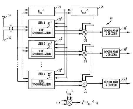
In Figure 2, a receiver 20 in the base station 12 includes signal processing
circuits
221w 22k for users 1, 2...K, coupled to the antennas 14 and 16. Each of the
signal
processing circuits contains synchronization circuits 23 ~..... 23k. All of
the user signals see
a similar interference environment as they all use the same frequency band and
the same
receive antennas. Thus, there exists for the user signals a universal
interference matrix 24,
which represents the interference subspace of all user signals. Accordingly,
the matrix 24
can be used for improved synchronization as well as the inputs of block 25 for
the array
CA 02326934 2000-11-24
Buehrer 8-5 (>
processing of all user signals instead of conventional individual processing.
The matrix is
the cross-correlation matrix of all the antenna inputs. It can be shown that
if there are any
interfering signals that are very large, the inverse matrix method will reduce
their value
and improve the quality of the signal to be used for synchronization and
detection
processing. The process of calculating the inverse matrix coefficients will be
described
hereinafter in conjunction with Figure 4.
The output of block 24 is the inverse of the cross-correlation matrix R~ and
is input
to block 25 to create R-~~ot. The function of block 25 will be explained in
conjunction with
Figure 4. The output of block 24 is also sent to the synchronization circuits
23'.... 23k.
The synchronization circuits will be explained in conjunction with Figures 3
and 5. The
outputs of the signal processing circuits 22'.... 22k are combined with the
output of the
inverse matrix 25 in a multiplier 26 as shown by the mathematical relationship
at the
bottom of Figure 2 and provided to standard demodulator and decoder circuits
28'.... 28k.
Before describing the signal processing in which the post-correlated signals y
are
combined with a channel estimate for processing by the demodulators and
decoders 28, it
is appropriate to describe the synchronization circuits 23 shown in Figure 3.
In Figure 3, the signal acquisition circuit 23 for each User 1, 2.... K
comprises a
series of delay stages dl, d2.... dN separated by delay elements 35, each
delay element
typically being a half chip delay. Each delay stage is comprised of
correlators 36 and 37
(i.e., equal to the number of antenna elements) and one summer/multiplier 39.
The
antennas 14 and 16 are coupled to correlators 36, 37 (each correlator
correlates with the in-
phase and quadrature signals) in each delay stage. The cotrelators correlate
the spreading
code of the user and the received signal samples, and are well known in the
art. The
spreading code is known by the correlator but the phase and the timing of the
signal of
interest are unknown. The acquisition circuit 23 receives incoming sample
streams from
each antenna which are correlated with the spreading code and combined in a
multiplier 39
with the inverse matrix coefficients to provide an output to a storage buffer
31 indicative of
the signal energy for that delay period. The mathematical relationship of the
operation
which takes place in multiplier 39 is given at the bottom of Figure 3. The
storage buffer
31 contains threshold information which allows it to determine the presence of
the signal
CA 02326934 2000-11-24
Buehrer 8-S
in any of the delays. The choice of threshold is a system design parameter.
The process of
calculating the energy for a single time delay will be described in further
detail in
conjunction with Figure 5.
Returning to Figure 2, the process of calculating the inverse matrix
coefficients
(blocks 24 and 25) will now be described in conjunction with Figure 4. In
Figure 4 the
process of calculating the inverse matrix coefficients begins in block 40 in
which an
index K is set to zero where K is the number of vector outer products which
are
averaged to create the cross-correlation matrix. In block 41 the incoming
signals from
the antennas 14 and 16 are accumulated in a register (not shown) over N chips
(i.e., the
symbols of the spreading code) or simply sampled every N chips. The first
option
requires more computation but will have a better signal-to-noise ratio. A
vector outer
product is calculated from the resulting signals in block 42. If M is the
number of
antennas, the vectors are M x I and the result of the outer product is M x M.
The outer
products are summed with previous results (if K > 1) in block 43. The index K
is
1 S increased by 1 in block 44. In block 45, a test is performed to determine
if the value of
K is larger than the predetermined window size. The window size should be
chosen to
be larger than the number of antennas for proper performance. If K + I is less
than the
window size, the process is returned to block 40 for another iteration and K
i~~ updated
for the next calculation. Once the number of K iterations equals the window
size, the
matrix is inverted in block 46 and the result is passed to the synchronization
circuit as
well as step 48. The process of inverting a matrix is well known and described
in the
text Matrix Computations by Golub and Van Loan, published by The John Hopkins
University Press, Baltimore and London, 1989, pages 142-154. Block 48
calculates the
larger matrix R-l~o~ for signal processing according to
p ... 0
0 R -' ... 0
R ,of ~ - . . . .
0 0 ...
CA 02326934 2000-11-24
Buehrer 8-5 g
The dimensions of R~l~a~ are ML x ML where M is the number of antennas and L
is the
maximum number of multipaths being tracked.
The process of determining the input signal timing (i.e., synchronization)
will now
be described in Figure S in conjunction with the signal acquisition circuit 23
shown in
Figure 3. At start 50 a sample point in time is determined to begin the
synchronization
process. In block 51, the search point is moved one-half chip ahead. (This is
represented
as a one-half chip delays 35 in Figure 3. The delay could be other than one-
half of a chip
and should be determined by the system designer.) In block 52, a signal sample
from each
antenna after correlation creates a 1 by 21 matrix vector [X1, ",, X2, ",] and
in block 53, the
same signal samples are used to create a second 2 x 1 matrix vector. The two
vectors are
used to pre-multiply and post-multiply the inverse of the Rtz matrix as shown
in Block 53
where U* represents the complex conjugate. The result of block 53 is
accumulated in
block 54 over a selected window size and stored in buffer storage 31 in Figure
3. In block
5~ the result in the buffer storage is compared to a threshold level
representative of signal
energy. The threshold is determined by the system engineer. If the signal
energy is less
than the threshold, the process is repeated until the threshold is exceeded or
all delays have
been searched. If the energy exceeds the threshold, a valid time delay of the
received
signal has been found and the synchronization process continues in block 57
until all
delays have been searched.
After synchronization, signal processing takes place in the receiver 20 shown
in
Figure 2, which will be described in conjunction with Figure 6. At start 60,
signal
processing begins in block 61 in which the received signal is correlated with
the spreading
code using timing information obtained in synchronization circuits 23 to
provide the post-
correlated signals yl," and yz," for the antennas 14 and 16. These are
expressed as a 1 x 2
matrix vector, [y,, ", y2, n] where n indicates the delay component (i.e.,
delayed version of
the received signal) and provided to the multiplier 26. (Again it should be
noted that in the
general case ofM antennas, the vector will be of dimensions 1 x M) In block
62, channel
1 For two antennas. In general the vector will be 1 by M
CA 02326934 2000-11-24
Buehrer 8-5 9
estimation is performed to obtain channel estimates for each antenna at each
delay n, al, n,
and a2, ". Channel estimation is performed to indicate the relative strength
and phase of the
channels at each delay and is expressed as a 2 x 1 matrix vector an = [a,,"
a2, n]. There are
several alternatives for performing channel estimation. Serial number
09/296,654 filed
May 1999, assigned to the assignee of the present invention is representative
of one
channel estimation compatible with the present invention and is fully
incorporated herein
by reference.
In block 63, the correlator outputs for each path on each antenna are combined
to
form a single vector y = [y 1 T y2T . . . yLT~ z where y" is the 2 x I vector
for each delay [y 1,
n y2, n] T. The multiplier 26 combines the antenna signals vector y with the
channel
estimate vector a = [a1T a2T ... a~T] T and the inverse matrix R-'got. This
multiplication is
represented by the mathematical relationship given at the bottom of Figure 2.
The
resulting signals for the users are provided in block 64 to the demodulators
and Viterbi
decoders as a combined output from the antennas (one for each receiver 22)
with improved
I S signal quality for the different users. The signal processing ends in step
65. Demodulation
(or detection) and Viterbi decoding are well known in the art.
Summarizing, the present invention discloses a receiver and method of
operation in
a CDMA system having one or more antenna arrays for antenna diversity. The
receiver
includes a universal matrix array for processing both signal delay estimation
(synchronization) and signal processing. Antenna diversity and universal
matrix array
processing improves synchronization and noise reduction in CDMA systems which
increases the number of simultaneous users possible for such a system while
reducing
receiver circuit computational complexity with respect to prior art systems
and methods.
While the invention has been shown and described in conjunction with the
specific
embodiment, various changes may be made without departing from the spirit and
scope of
the invention as defined in the appended claims in which: