Note: Descriptions are shown in the official language in which they were submitted.
CA 02327023 2003-O1-15
ENDPLATE FOR USE WITH OUTBOARD BEARING DESIGNS
CROSS-REFERENCE TO RELATED APPLICATIONS
This application is related to the following U.S. patents,
each of which has the same filing date as the present
application: "Shaft Extension for Use with Outboard Bearing
Designs", filed by Walter Goettel, Roger Drummond, Ronald
Shaffer, James Varney and Brian Cunkelman, U.S. Pat. No.
6,419,465, and "Combined Bearing Plate and Stator Frame
Casting", filed by James Varney, Walter Goettel, Ronald Shaffer,
and Brian Cunkelman, U.S. Pat. No. 6,376,950. Additionally, the
present application is directed to similar subject matter as is
disclosed in U.S. Pat. No. 6,447,267, entitled "Locomotive Air
Compressor with an Electric Motor Supported by an External
Bearing".
1
CA 02327023 2000-11-21
FIELD OF THE INVENTION
The present invention relates, in general, to an air
compressor that is powered by an electrical motor.
More particularly, the present invention relates to an
air compressor, driven by an electrical motor, which is used
to supply compressed air to the air brake system of a railed
vehicle (e. g., a train or light rail vehicle).
Even more particularly, the present invention relates to
an apparatus (or kit) which enables an air compressor that
supplies compressed air for a braking system and that is
driven by an electrical motor to be retrofitted so as to
provide a "third" or "outboard" bearing for the crankshaft of
the air compressor. As explained fully below, the provision
of such a "third" or "outboard" bearing significantly reduces
the possibility that the rotor of the electrical motor will
"cant" with respect to the stator of the electrical motor.
Such relative angular displacement between the rotor and
stator can significantly degrade the performance of the
electrically powered air compressor, and can even lead to
failure of the combined system.
BACKGROUND OF THE INVENTION
The following background information is provided to
assist the reader to understand the invention described and
claimed herein. Accordingly, any terms used herein are not
2
CA 02327023 2000-11-21
intended to be limited to any particular narrow
interpretation unless specifically so indicated.
The use of an air compressor to supply compressed air
for the operation of an air brake system is well known. In a
railed vehicle, the air compressor is typically located in
the locomotive of the train, etc. Earlier air compressors
for trains were often powered via a power takeoff linkage
from the engine of the locomotive. More modern diesel
locomotives typically employ electric motors to supply
tractive power, with the electrical power being generated
onboard. The air compressors of diesel locomotives are,
therefore, typically driven by electrical power, which is
readily available onboard.
A main compressed air reservoir is normally employed.
The main reservoir supplies compressed air to the "brake
pipe," which runs the length of the train. The electric
motor that drives the air compressor is typically started and
stopped on an "as needed" basis, so as to maintain the
compressed air pressure in the main reservoir within
determined limits. Thus, the electric motor may be started
and stopped repeatedly over the service life of the unit.
Figure 1 is a simplified isometric view of an air compressor
unit that is widely employed within the railroad industry for
supplying compressed air for use in air braking systems,
3
CA 02327023 2003-O1-15
namely, a "3-CD" Air Compressor manufactured by the Westinghouse
Air Brake Company~ division of Wabtec Corporation~ (1001 Air
Brake Avenue, Wilmerding, Pennsylvania). Particulars of the "3-
CD" Air Compressor are set forth in the pamphlet entitled
"Instructions for Disassembly, Repair and Assembly of '3-CD' Air
Compressors," published by the above-identified Westinghouse Air
Brake Company~ (copyright 1994).
In Figure 1, a "3-CD" air compressor is generally indicated
by reference numeral 10. The air compressor 10 includes a
crankshaft 12, which is driven by an external power source and
which, in turn, drives the internal compression parts of the air
compressor 10 (e.g., pistons, valves, etc.). The crankshaft 12
is rotationally supported and positioned by typically two
inboard rotational bearings, one such inboard bearing 14 being
shown in phantom in Figure 1. The inboard bearing 14 is
supported and positioned by a generally key-shaped bearing plate
16, which also serves to close a portion of the crankcase of the
air compressor 10. It will be seen that the crankshaft 12
projects outward from and beyond the bearing plate 16.
4
CA 02327023 2000-11-21
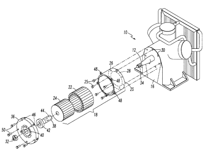
Figure 2 illustrates the manner in which an electric
motor, generally indicated by reference numeral 18, has
heretofore been mated with the air compressor 10, in order to
provide power to the air compressor 10. The electric motor
generally includes a stator frame 20, a stator 22, and a
rotor 24. The stator frame 20 has, in the past, been
connected to the exposed face of the bearing plate 16 by
bolts 25 which pass through holes 26 provided in an inwardly
projecting lip 28 provided on the rearward face of the stator
frame 20. The bolts then engage a series of threaded blind
holes 30 provided in the outwardly exposed face of the
bearing plate 16. The stator frame is therefore
"cantilevered" from the exposed face of the bearing plate 16
and secured in this position by the bolts.
The stator frame 20 may be viewed as the "housing" of
the electric motor 18, serving to enclose the stationary
stator 22 and the rotating rotor 24. The electric motor 18
is typically an induction type motor, and often a three-phase
AC induction type motor. The stator 22 typically includes a
plurality of coil windings and is fixedly mounted to the
interior surface of the stator frame 20. The rotor 24 non-
rotationally engages the protruding portion of the
crankshaft 12 (i.e., is fixedly mounted with respect to the
crankshaft 12) and is therefore encircled by the fixed
5
CA 02327023 2000-11-21
stator 22. Typically, the rotor 24 is press fitted onto the
crankshaft 12, and a protruding axial spline provided on the
interior cylindrical surface of the rotor 24 engages a groove
provided on the crankshaft 12.
An endnut 32 may engage a threaded portion 34 provided
on the outboard distal end of the crankshaft 12 to axially
retain the rotor 24 on the crankshaft 12.
The dimensional difference between the interior diameter
of the stator 22 and the exterior diameter of the rotor 24 is
relatively small, typically on the order of between
about 40/1000 and about 50/1000 of an inch. If the rotor 24
is not maintained in a substantially central alignment with
respect to the encircling stator 22, the rotor 24 may come
into contact with the stator 22. Such rubbing degrades
performance. In severe cases, contact of the rotor 24 with
the stator 22 can short out the windings of the stator 22,
thereby "burning out" the electric motor 18.
During startup of the electric motor 18, it has been
discovered that a non-symmetric radial force is exerted on
the rotor 29, and thus the crankshaft 12. Thus, during
startup, forces are exerted on the rotor 24 which tend to
"cant" the rotor 24 with respect to the stator 22. Over time
in service, these forces can lead to the rubbing described
6
CA 02327023 2003-O1-15
above and, ultimately, can result in the above-described
shorting and burning out of the electric motor 18.
There is disclosed in U.S. Patent 6,447,267 entitled
"Locomotive Air Compressor with Motor Supported by Outside
Bearing", assigned to the same assignee as the present
application, various arrangements for providing what is herein
referred to as a "third" or (alternatively) an "outboard"
bearing. Such a third or outboard bearing provides additional
support for the outboard distal end of the crankshaft I2, and
considerably prevents (or at least substantially reduces) any
canting of the crankshaft 12 and the rotor 24 attached thereto
with respect to the stator 22.
There are an extremely high number of air compressors of
the "3-CD" type in service. It is desirable, therefore, to
provide an apparatus and method for "retrofitting" such in-
service air compressors with such a third or outboard bearing.
Hr~ apparatus and method for performing such a retrofit are
disclosed herein.
Since relatively tight tolerances are required in the
alignment between the stator frame 20 (which ultimately
7
CA 02327023 2000-11-21
determines the positioning of the stator 22> and the
crankshaft 12 (which ultimately determines the positioning of
the rotor 24), it has heretofore been the practice in the
industry to carefully machine both the outwardly exposed face
of the bearing plate 16 and the rearward face of the stator
frame 20 (i.e., including the inwardly projecting lip 28
provided on the rearward face of the stator frame 20) to
relatively exact dimensions, in order to ensure that the
rotor 29 remains rather exactly centered with respect to the
stator 22.
Such precise machining of the previously separate
bearing plate 16 and stator frame 22 is an expensive
procedure, and is not always entirely satisfactory in its
implementation. A combined bearing plate and stator frame
which eliminates the need for separate machining of the
bearing plate and stator frame separately to the
aforementioned tight tolerances required, and which provides
for substantially increased precise alignment of the rotor 24
within the stator 22 over use in service, is disclosed
herein.
OBJECTIVES OF THE INVENTION
Therefore, one objective of the invention is the
provision of an endplate for attachment to a stator frame of
an electric motor used to drive an air compressor, the
8
CA 02327023 2000-11-21
endplate being able to accommodate an outboard rotational
bearing within which the distal end of the crankshaft can
rotate and which provides additional structural support to
the distal end of the crankshaft so as to prevent, or at
least significantly reduce, any canting of the crankshaft
(and the rotor mounted thereon) with respect to the stator of
the electric motor.
Another objective of the invention is the provision of
such an endplate that can be easily retrofit to an already
existing electric motor driven air compressor so as to
provide the benefits of an outboard rotational bearing
thereto.
A still further object of the invention is the provision
of a kit through the use of which an already existing
electric motor driven air compressor can be retrofitted with
an outboard rotational bearing.
In addition to the objectives and advantages listed
above, various other objectives and advantages of the
invention will become more readily apparent to persons
skilled in the relevant art from a reading of the detailed
description section of this document. The other objectives
and advantages will become particularly apparent when the
detailed description is considered along with the drawings
and claims presented herein.
9
CA 02327023 2000-11-21
SUI~tARY OF THE INVENTION
The foregoing objectives and advantages are attained by
the various embodiments of the invention summarized below.
In one aspect, the invention generally features an
endplate for attachment to a stator frame of an electric
motor used to drive an air compressor. The air compressor
has a crankshaft rotationally supported by at least one
rotational bearing, and the electric motor includes the
stator frame, a stator element mounted to and within the
stator frame, and a rotor element rigidly mounted on a
portion of the crankshaft for rotation therewith. The
crankshaft projects through the stator element and terminates
in a distal end. The endplate is adapted for mounting to the
stator frame so as to provide support for mounting an
additional rotational bearing for rotationally supporting the
distal end of the crankshaft on an opposite side of the rotor
from the at least one rotational bearing. The endplate
includes a cap member and an attachment mechanism for
attaching the cap member to the stator frame, the cap member
including a rotational bearing housing for mounting and
positioning a rotational bearing thereon and the rotational
bearing housing being substantially positioned in
juxtaposition to the distal end of the crankshaft when the
10
CA 02327023 2000-11-21
cap member is attached to the stator frame by the attachment
mechanism.
In another aspect, the invention generally features an
improvement in combination with an air compressor powered by
an electric motor, the air compressor having a crankshaft
rotationally supported by a rotational bearing and the
electric motor being housed within a stator frame. The
improvement includes an endplate for attachment to the stator
frame to provide an outboard rotational bearing for
supporting a distal end of the crankshaft. The endplate
includes a cap member and an attachment mechanism for
attaching the cap member to the stator frame. The cap member
has a rotational bearing housing for mounting and positioning
a rotational bearing thereon. The rotational bearing housing
is substantially positioned in juxtaposition to the distal
end of the crankshaft when the cap member is attached to the
stator frame by the attachment means.
In a further aspect, the invention generally features a
kit for retrofitting an electric motor driven air compressor
so as to provide the electric motor driven air compressor
with an outboard rotational bearing. The electric motor
driven air compressor includes a bearing plate having an
external exposed face, a crankshaft projecting outward
through the bearing plate and terminating in a distal end, a
11
CA 02327023 2000-11-21
stator frame fixedly connected to the external exposed face
of the bearing plate, a stator fixedly connected within the
stator frame, and a rotor fixedly connected to the crankshaft
and disposed within the stator. The kit includes a cap
member for attachment to the stator frame, an attachment
mechanism for attaching the cap member to the stator frame,
and a shaft extension for attachment to the distal end of the
crankshaft to axially extend the crankshaft. The cap member
includes a rotational bearing housing for mounting and
positioning the outboard rotational bearing thereon such that
the rotational bearing housing is positioned in substantial
juxtaposition to the terminal end of the crankshaft when the
cap member is attached to the stator frame by the attachment
means.
BRIEF DESCRIPTION OF THE DRAWINGS
Figure 1 is an simplified isometric view of a ~~3-CD"
type air compressor, of the type described herein.
Figure 2 is an isometric exploded view of a ~~3-CD" type
air compressor equipped with an electric motor according to
practices heretofore employed in the industry.
Figure 3 is an isometric exploded view of a ~~3-CD" type
air compressor equipped with an electric motor and provided
with a third or outboard bearing.
Figure 4 is an isometric view of an endplate.
12
CA 02327023 2000-11-21
Figure 5 is an isometric view of the endplate of
Figure 4, viewed from a reverse plane.
Figure 6 is an isometric view of a shaft extension.
Figure 7 is an isometric exploded view of a "3-CD" type
air compressor having a combined bearing plate and stator
frame, equipped with I an electric motor, and provided with a
third or outboard bearing.
Figure 8 is an isometric view of a combined bearing
plate and stator frame.
Figure 9 is an isometric view of the combined bearing
plate and stator frame of Figure 8, viewed from a reverse
plane.
13
CA 02327023 2000-11-21
DETAILED DESCRIPTION OF THE
PREFERRED EMBODIMENTS OF THE INVENTION
Referring now to Figure 3, an apparatus (or "kit") for
retrofitting the air compressor 10 with a third or outboard
bearing generally includes an endplate 36 and a shaft
extension 38. The stator frame 20 is cantilevered from the
exposed outboard face of the bearing plate 16 of the air
compressor 10 through any suitable means. For example, the
stator frame 20 may be secured to the bearing plate 16
through the use of the bolts 25 which pass through the
holes 26 formed in the inwardly extending radial lip 28
formed on the rear (i.e., inward) face of the stator
frame 20, the bolts 25 terminating in the threaded blind
holes 30 formed in the bearing plate 16.
The endplate 36 includes a bearing housing 40, which
provides a mounting for a third or outboard bearing 92. The
stator 22 is fixedly mounted to the stator frame 20, and the
rotor 24 is fixedly mounted to the crankshaft 12, for
example, in the conventional manner as described above.
The shaft extension 38 is of general cylindrical shape
and includes a threaded blind hole 49 which threads onto the
distal end of the crankshaft 12. Thus, the shaft extension
extends the crankshaft 12 to a length which is sufficient
14
CA 02327023 2000-11-21
such that its distal end is rotationally mounted in and
positioned by the third or outboard bearing 42.
The endplate 36 is provided with a series of
throughgoing holes 46, and a corresponding series of lugs 98
are provided for attachment to the axially outward periphery
of the stator frame 20. An equal series of bolts 50 pass
through the holes 46 and threadingly engage the lugs 48,
thereby securely positioning the endplate 36 with respect to
the stator frame 20. Accordingly, the third or outboard
bearing 42 is securely positioned with respect to the stator
frame 20, and thence to the bearing plate 16.
The apparatus described immediately above with respect
to Figure 3, when attached to the arrangement shown in
Figure 2, by providing an outboard rotational bearing support
for the distal end of the crankshaft 12, substantially
reduces any tendency of the rotor 24 to become canted with
respect to the stator 22.
Referring now to Figures 4 and 5, the endplate 36, shown
in more detail therein, generally includes a cap member,
which is preferably provided in the form of disk-shaped
portion 52, an outer rim 54 projecting axially from the
periphery of the disk-shaped portion 52, and an inner
flange 56, axially spaced inward from the outer rim 54. The
inner flange 56 is appropriately machined so as to snugly
15
CA 02327023 2000-11-21
mate with the axially outward edge of the stator frame 20.
For example, a mating stepped surface may be machined into
each of the corresponding surfaces. The throughgoing holes
46 are preferably provided in stanchions 58 located generally
between the outer rim 54 and the inner flange 56. The
bearing housing 40 is preferably provided in the form of an
collar 60 projecting inwardly from the disk-shaped
portion 52, which is preferably provided with reinforcing
ribs 62 and ventilation openings 69.
Referring now to Figure 6, the shaft extension 38 is
generally cylindrical in form and is preferably provided with
a tool engaging portion 66 (for example, in the form of
opposing flats or a hexagonal head) to allow torque to be
applied thereto for threading on/off the threaded portion 34
of the crankshaft 12. As noted above, the blind hole 44 is
internally threaded, as through the provision of internal
threads 68.
Figure 7 illustrates the use of a combined bearing plate
and stator frame, generally designated by reference
numeral 70, in the air compressor 10. While it is not a
requirement that the combined bearing plate and stator
frame 70 be used in combination with the endplate 36 and
third or outboard bearing 42 in order to rotatingly support
the distal end of the crankshaft 12, this is the preferred
16
CA 02327023 2000-11-21
combination. However, the combined bearing plate and stator
frame 70 could be used alone, and would still provide the
advantage of not requiring that the bearing plate and stator
frame be machined to the required tight tolerances
separately.
When the combined bearing plate and stator frame 70 is
employed, as shown by reference numeral 72 in Figure 7, the
crankshaft 12 is preferably provided with an additional
extended length as compared to the length currently practiced
in the industry. The crankshaft 12, which is usually
produced as a single casting, is therefore preferably of an
elongated length when using the combined bearing plate and
stator frame 70. However, the combined bearing plate and
stator frame 70 may still be used with a conventional length
crankshaft 12, if, as shown optionally in Figure 7, the shaft
extension 38 shown most particularly in Figure 6 is used to
extend the length of the crankshaft 12.
Preferably, the combined bearing plate and stator
frame 70 is produced as a single casting which is then
machined to the required tolerances for connection to the air
compressor 10 and for the attachment of the endplate 36 and
other components thereto.
Referring now most particularly to Figures 8 and 9, the
combined bearing plate and stator frame 70 generally includes
17
CA 02327023 2000-11-21
a cylindrical-shaped or bowl-shaped stator frame portion 74
and a bearing plate portion 76. The bowl-shaped stator frame
portion 74 includes a cylindrical wall portion 78, one end of
which 80 is open for receiving the stator 22, and an end
wall 82, which partially encloses the other end of the
cylindrical wall portion 78. The bearing plate portion 76
abuts, overlays, and is integrally formed with the end
wall 82. An aperture 84 is formed in the end wall 82 and is
encircled by a bearing receptacle 86, preferably provided in
the form of an outstanding collar 88. The bearing plate
portion 76 preferably includes a horseshoe-shaped portion 90,
which surrounds both the aperture 84 and the bearing
receptacle 86, and a wedge-shaped portion 92, which extends
radially outward from the horseshoe-shaped portion 90.
The lugs 48 extend radially from the cylindrical wall
portion 78 adjacent the open end 80, allowing the
endplate 36 to be secured to the combined bearing plate and
stator frame 70 through use of the bolts 50.
The combined bearing plate and stator frame 70 is
dimensioned to be fitted into the open space shown by
reference numeral 94 in Figure 7, where a conventional
bearing plate 16 of the air compressor 10 would be normally
accommodated. The conventional inboard bearing 14 of the air
compressor 10 is mounted in the bearing receptacle 86 formed
18
CA 02327023 2000-11-21
on the inboard face of the combined bearing plate and stator
frame 70.
While the present invention has been disclosed by way of
a description of a particularly preferred embodiment or a
number of particularly preferred embodiments, it will be
readily apparent to those of ordinary skill in the art that
various substitutions of equivalents can be effected without
departing from either the spirit or scope of the invention as
set forth in the appended claims.
19