Note: Descriptions are shown in the official language in which they were submitted.
CA 02327083 2000-10-02
WO 99/51405 PCT/EP99/02266
Aaaaratus for removing' broken-out ~oieces from a sheet of
material or the like
The invention concerns an apparatus for removing broken-out
pieces, in particular waste portions, from a sheet of material containing
blanks or the like flat portions, as set forth in the classifying portion of
the
independent claims.
1o EP 0 446 702 B1 to the present applicant discloses that automatic
stamping machines for the production of blanks from sheets of card in the
folding box industry have been provided for more than 30 years with
breaking-out devices which are preferably arranged in a setting-up table
outside the stamping machine. Such a breaking-out station is of particular
i5 importance in terms of manufacture as in the event of incorrect use it
involves the highest proportion of the total setting-up time and a poorly
set breaking-out station results in continual disturbances in the production
procedure.
In the breaking-out station the stamped cardboard sheet, after
20 reaching a predetermined detest position, on the breaking-out surface
which is usually provided by a breaking-out board or a female die, is freed
of the waste by means of breaking-out pins or cutting edges which press
from above.
Development in the breaking-out procedures involved firstly
25 entailed the top tool pin which presses downwardly from above and which
passes the waste portion through the opening in the breaking-out board.
There was then added an additional bottom tool with bottom pins, which
are aligned with the top tool pins and which clampingly hold the waste
portion. As a breaking-out tool can reliably break out a waste portion only
3o when there is a certain force-locking engagement between the tool and
the waste portion, the above-mentioned bottom pins have proven to be an
1 AMENDED PAGE
CA 02327083 2000-10-02
advantageous resistance at the moment when the breaking-out tool or
breaking-out member comes to bear against the waste portion.
If there is a wish to avoid using a clamping tool, the breaking-out
opening in the breaking-out surface must be smaller at various locations,
than the waste portion which is associated therewith, so that the waste
portion rests with a relatively high friction, in small surface areas, on the
breaking-out surtace or female die. When the breaking-out pin comes into
contact with the waste portion, the above-mentioned resistance occurs by
virtue of the friction which is then produced. When the breaking-out pin
io and the waste portion pass through the opening, friction occurs at the
relatively close walls of the hole, whereby a certain force-locking action is
achieved.
DE-A-25 35 452 discloses the so-called DYN-pin, namely a
breaking-out pin having a tip or point whose substantially conical side
walls are of contours which are concave in cross-section, with a smooth
surface. In the breaking-out procedure, that tip bears against the waste
portion which, by virtue of being supported on the edges of the opening,
opposes the tip with such a level of resistance that the tip can penetrate
slightly into the material of the waste portion. That prevents unwanted
lateral deflection movement of the waste portion. As it passes through the
opening, the waste portion bends, and the stressing force between it and
the wall of the opening is intended to afford the DYN-pin sufficient friction
for the desired force-locking engagement with the waste portion; that
could then possibly make a bottom tool in itself unnecessary, when using
the DYN-pin.
As a simplification for breaking-out tools, above-mentioned EP 0
446 702 B1 proposes a support means which is a surface which is movable
and/or resilient within the opening - at least in part in an inclined position
- at a spacing relative to the breaking-out surface and which, in its rest
3o position, engages substantially parallel beneath the waste portion in the
sheet of material and which, upon movement - that is to say primarily
2
CA 02327083 2000-10-02
upon downward movement - of the waste portion, is transferred, by the
breaking-out member, into an angle of inclination with respect to the
sheet of material. The resilient surtace can be in the form of a tongue-like
spring which is fixed at one end to the breaking-out surtace - substantially
aligned therewith in the rest position - while the free end of the tongue-
like spring is arranged in the opening. Also described are angle portions
having one limb aligned with the breaking-out surtace while the other limb
thereof is pivotably mounted beneath the breaking-out surface and is
subjected to a spring loading. The resilient surface can also be afforded by
1o rubber profile members or by bristles.
An apparatus as set forth in the opening part of this specification is
described in WO-A-97/30829. Extending from the edge of an opening in a
female die at a right angle are straight slots or grooves which are adjoined
at a large spacing relative to the opening by a respective enlargement
i5 portion of rectangular configuration in plan view, as a receiving space for
a
block-like portion which forms the rear plug-in portion of an otherwise
strip-like support means which projects with an end portion into the
opening. The block portion which is wider in relation to the support web
portion formed on the component tapers conically in the plug-in direction.
20 The end portions of the support web portions, which are disposed in the .
opening, engage under a waste portion and are urged downwardly at the
end by the pressure of a breaking-out tool resting thereon, along a bend
line which is at the transition to the block portion, until they release the
waste portion in a downward direction.
25 Finally, DE-C-41 24 089 provides a cuboidal breaking-out tool of
rectangular cross-section, from the pressing end of which two pressing
tips or points project, in line with the two narrow sides thereof.
In consideration of that state of the art relating to the breaking-out
procedure, the inventor set himself the aim of substantially improving the
3o removal of waste portions from sheets of material and simplifying the
tools required for that purpose. In particular the invention seeks to
AMENDED PAGE
CA 02327083 2000-10-02
provide that those tools can be used for the treatment of very small waste
pieces.
That object is attained by the teaching of the independent claim;
the appendant claims set forth advantageous developments. In addition
the scope of the invention embraces all combinations of at least two of the
features disclosed in the description, the drawings and/or the claims.
In accordance with the invention the connection pairing comprises
an undercut receiving groove on the one hand and on the other hand a
coupling bar which can fit thereinto and which is preferably disposed on
the support tool; the receiving groove is disposed at the edge of the
opening in the female die, but the association can also be reversed. The
support tool is preferably an angle portion with one of said connection
component parts on its one limb and with another flexible limb which
forms the support surface.
In another embodiment which is in accordance with the invention
the connection pairing comprises at least one receiving groove in the
female die at the edge of the opening thereof on the one hand and a
portion, which can be fitted thereinto, of a vertical limb of the support tool
on the other hand, which is vertically fitted on to or into same.
ZO In a particular embodiment that vertical limb can comprise a hollow
profile portion which can be fitted on to a plug-in profile portion of the
female die.
The angle portion with the limb which is vertical in the position of
installation, and the other flexible limb which forms the support surface
and which is horizontal in the position of installation can be formed overall
from a material of limited flexibility, which ensures a long service life.
In a preferred embodiment the connection pairing comprises at
least one vertical receiving groove - extending in the breaking-out
direction - in the female die at the edge of the opening thereof on the one
hand, and a portion - which can be fitted thereinto - of a vertical limb of
the support tool on the other hand. The respective cross-sections of the
AMENDED PAGE
CA 02327083 2000-10-02
coupling bar and the opening are advantageously to be of a rectangular
configuration and thus define an operative position which is easy to bring
about. A plurality of such connection pairings can possibly be provided.
It has proven to be desirable if the flexible limb forming the support
surface has an edge opening which is delimited at both sides by cantilever
portions, and, at a spacing relative to the edge opening, at least one inner
opening. That configuration affords a particularly desirable support surface
which is stable in respect of shape and nonetheless flexible.
In accordance with the invention the above-mentioned pin-like
1o plug-in element is on the vertical limb and extends at a spacing relative
thereto and is respectively adapted to be inserted into an opening
provided in the female die at a spacing relative to the receiving groove.
Like also the opening which receives the plug-in element, the plug-in
element is to be of a rectangular cross-section, while the plug-in element
projects either at a spacing relative to the back surface of the vertical limb
or at a spacing relative to the flank surface of the vertical limb, from a
respective transverse web portion. In the structure involving association
with the flank surtaces, a pair of plug-in elements is preferred.
In a particular embodiment the flank surfaces of the vertical groove
2o are stepped, wherein the vertical limb is supported in the back region,
which is narrower in cross-section, of that stepped vertical groove, and
therefore the horizontal limb projects beyond the wider front region of the
vertical groove.
In another embodiment the vertical limb is to be connected with a
coupling pairing to a limb, which extends in the vertical groove, of an
angle bracket whose other limb is connected to the female die, preferably
by means of force-locking engagement. It is however also possible to
provide a pocket at the underside of the female die, for the limb of the
angle bracket, whereby that limb projects in positively locking
engagement into same.
AMENDED PAGE
CA 02327083 2000-10-02
So that the broken-out piece is possibly held after the releasing
procedure, at least one catch finger can be arranged downstream, in the
breaking-out direction, of the limb forming the support surface; a pair of
catch fingers which are in flanking relationship on both sides is however
preferred. The catch fingers increase in width from their free end towards
the limb formed thereon, in terms of longitudinal section, for the purposes
of increasing the degree of flexibility thereof. In another embodiment the
horizontal limb is flanked by side portions which are formed on the other
limb, and therefore extend vertically.
Another embodiment provides a support tool with a partial frame
which is approximately U-shaped in cross-section and which comprises a
back portion having the coupling rib and having two parallel side walls; a
sa AMENDED PAGE
CA 02327083 2000-10-02
support plate for the broken-out portion is arranged between said side
walls, pivotably about an axis which is generally horizontal in the position
of use.
The feature whereby the breaking-out tools extend between
surfaces of the support means, said surfaces being movable in the
breaking-out direction, results in a higher level of operational reliability
as
the arrangement affords a kind of tongs or pincer engagement; that
cannot be achieved in the state of the art as the breaking-out tools are
usually within the contour which is defined by the free edges of the
1o surfaces.
Engagement of the breaking-out tools can also become more
efficient when an edge opening is disposed in opposite relationship to the
free end of the tools, the edge opening extending from the free edge of
the support surface.
It has proven to be desirable to associate with the support surtace,
as a breaking-out tool, a pressure pin having a rounded free end or a fork
member with one or more finger-like fork prongs, preferably of flat cross-
section.
In particular small waste pieces also take part in the bending
2o movement of the breaking-out tool, in such a way that they assume a
perpendicular position. When dealing with smooth cardboard surfaces,
that results in slipping movement of the pressure pins on the surface of
the cardboard and thus results in the waste portions being unsatisfactorily
broken away. Therefore, for the sake of better engagement, the free end
of the pressure pin or the fork prongs is in the form of a rough surface.
That rough surface can be formed by a coating which for example is
formed with oxides, carbides, corundum or the like and is possibly applied
by means of thermal spraying. Another embodiment according to the
invention provides a rough surface with irregularities such as teeth or
steps in the surface of the pressure pin or the fork prong or prongs. The
6
CA 02327083 2000-10-02
irregularities can be produced by a mechanical, chemical or electrical
treatment.
By virtue of the rough surface described - for which protection is
claimed separately - the arrangement affords the desired firm
engagement and the piece which is to be broken away is effectively
prevented from sliding away. For that purpose, it has been found sufficient
for the axial height of the rough surface to correspond at most to the
diameter of the pressure pin or the width of the fork prong, preferably
making it less than 5 mm.
1o Each fork member is to project from a plate-shaped male die and in
accordance with the invention it is connected thereto by a portion of the
fork member which has clamping noses and which can also have
abutments which are guided against the underneath surface of the male
die.
Other insert portions for the female die are shaped support portions
which are arranged in the opening of the female die at the edge thereof
and which are fitted to plug-in profile members and which are disposed in
mutually opposite relationship and which are provided with mutually
directed radial support lips of elastic material. Preferably that shaped
support portion is an angle portion of which one limb is the support lip,
while the other limb formed thereon is formed by a hollow profile
member; the latter preferably corresponds to a cylindrical cup and is
pressed on to a plug-in profile member by a simple assembly procedure in
the breaking-out direction.
2s The scope of the invention also embraces clip-like tools which are
fixed at the opening in the female die and which each include a respective
frame portion' from which resilient support tongues project inwardly or on
which are arranged inwardly disposed support plates which can be guided
about a pivot axis; that arrangement therefore affords simple additional
tools in the form of spring clips or mechanically moved clips which would
even permit standardisation of the tools.
7
CA 02327083 2000-10-02
Further advantages, features and details of the invention will be
apparent from the description hereinafter of preferred embodiments and
with reference to the drawing in which:
Figure 1 is a plan view of a support tool for a waste portion for the
removal thereof from cardboard sheets in the corrugated cardboard and
folding box industry,
Figure 2 is a side view of Figure 1,
Figure 3 is a side view corresponding to Figure 2 of another
embodiment,
io Figures 4 through 7 are diagrammatically illustrated successive
method steps with a breaking-out board which is shown in section and
which includes a support tool as shown in Figures 1 and 3 and with which
a breaking-out tool is associated,
Figure 8 is a view on an enlarged scale approximately
corresponding to Figure 6, with a support tool which is modified in relation
to Figure 6, and another breaking-out tool,
Figure 9 is a plan view of a part of a further breaking-out board with
support tool and breaking-out tool as shown in Figure 8,
Figure 10 is a view corresponding to Figure 9 of a further
zo embodiment,
Figure 11 is a perspective view of a further support tool with
breaking-out tool and the indicated end positions of a movable support
plate,
Figure 12 is a view corresponding to Figure 11 of an arrangement
with a breaking-out tool,
Figure 13 is a diagrammatic view in section relating to Figures il
and 12,
Figures 14 and 15 respectively show a support tool in plan and a
breaking-out tool illustrated in section,
Figure 16 is a front view in section of the arrangement shown in
Figure 9,
8
CA 02327083 2000-10-02
Figure 17 shows the mounting arrangement for the breaking-out
tool of Figure 16 taken along line XVII-XVII therein,
Figure 18 is a front view of a plate-like breaking-out tool in two
embodiments,
Figure 19 shows two side views in relation to Figure 18,
Figure 20 is a view in section on an enlarged scale through a further
embodiment of the breaking-out tool of Figure 18,
Figure 21 is a view corresponding to Figure 18 of a further
breaking-out tool,
i0 Figure 22 is a side view relating to Figure 21,
Figure 23 is a front view of another breaking-out tool,
Figures 24 through 26 show side views of three other embodiments
of the breaking-out tool,
Figures 27 and 28 show the breaking-out tool of Figure 24 in two
i5 stages of a breaking-out operation,
Figures 29 and 30 respectively show a perspective view of a unit
comprising a support tool and a breaking-out tool,
Figure 31 shows a perspective view of another breaking-out tool,
Figure 32 shows a perspective view of another embodiment of a
20 support tool,
Figures 33 and 34 show two views corresponding to Figures 4 and 5
respectively of a working operation with support tools as shown in Figure
32,
Figures 35 through 38 show plan views of special tools having a
25 spring action,
Figures 39 and 40 show plan views of special tools having a
mechanical action,
Figures 41, 43 and 46 show sectional views of breaking-out boards
with respectively inserted support tools,
30 Figures 42, 44 and 45 show plan views of the structures shown in
Figures 41, 43 and 46,
9
CA 02327083 2000-10-02
Figure 47 is a front view of the support tool of Figures 43 and 44,
and
Figure 48 is a perspective view of the support tool of Figures 46 and
47.
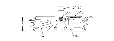
Cardboard sheets 10 which are used in the folding box industry
have stamped blanks for folding boxes or the like, with waste portions 12
being produced in or on the blanks. Downstream of a stamping station
which is not shown in the drawing for reasons of enhanced clarity thereof,
the stamped cardboard sheet 10 passes on to a breaking-out board or a
i0 female die 14 of a thickness b for example of 12 mm, on which the sheet
is freed of its waste portions 12; the waste portions 12 are disposed
over openings 16 which are of a configuration designed in dependence on
the contour of the waste portions 12 and at which, in the cross-sectional
view in Figures 4 through 7, an upper frame portion 17 with a vertical wall
is followed by a downwardly opening conical portion 18.
Fixed in the opening 16 is a support tool 20 for the waste portion
12, which as shown in Figures 1 and 2 is a kind of angle portion having
two limbs 22 and 24 of flexible plastic material with a high level of
endurance in relation to fluctuating loadings thereon. Projecting from the
limb 22 which extends vertically in the position of installation is a coupling
rib 27 which has flanks 26 of an undercut configuration and which is
inserted into a vertical groove 28 of dovetail-shaped cross-section in the
female die 14. As Figure 9 clearly shows the vertical groove 28 extends
from a wall surface 15 defining the opening 16.
The resilient horizontal limb 24 of the support tool 20, of a thickness
a, has an inner opening 30 and at its free edge 25 an edge opening or
recess 32; two prong-like cantilever portions 34 of the horizontal limb 24,
which flank the edge opening 32, are curved in longitudinal section and
each form a kind of bowl or cup.
In the embodiment shown in Figure 3, formed on the vertical limb
22 is a catch finger 38 for the waste portion 12. The catch finger 38 is
CA 02327083 2000-10-02
curved downwardly in its longitudinal section and narrows towards its free
end 36.
The waste portion 12 which rests on the surface 25 of the horizontal
limb 24 is subjected to a pressure from above by a breaking-out member
or tool in the form of a pressure pin 40 with a roughened part-spherical
pressure end which is similar to a fingertip, with the contact between the
pressure end and the waste portion being in point form or - for example in
Figures 8 and 12 - as a fork member 41, in substantially linear
configuration; the flat fork prongs 42 of the fork member 41 are aligned
with each other. Both the part-spherical pressure end of the pressure pin
40 and also the flat ends of the above-mentioned fork prongs 42 are
provided with a coating 44, affording the roughness thereof, of an axial
height h of between about 4 and 10 mm. The coating was produced for
example by thermal spraying from aluminum oxide, corundum, carbide
grains or the like.
The preferred height h is at most equal to the diameter d of the
pressure pin 40 and the roughness depth is less than 0.5 mm. That
coating can also be replaced by roughening of the surface of the pressure
pin or the flat prong 41, which is effected chemically, electrically or - for
example by means of sand blasting - mechanically.
In the downward movement of the breaking-out tool or tools 40,
41, the waste portion 12 is separated by pressure from the cardboard
sheet 10 and carried away downwardly in the breaking-out direction x.
In the embodiment shown in Figure 9 the edge opening 32 is at its
end of a part-circular contour and the horizontal limb 24 is flanked by side
portions which respectively form the above-described catch fingers 38 and
which - like also the horizontal limb 24 itself - are formed on the vertical
limb 22.
Figure 10 indicates a connection pairing between the support tool
20~ and the female die 14, which is modified in relation to the embodiment
shown in Figure 9; the female die 14 engages with a vertical bar 29 which
11
CA 02327083 2000-10-02
projects from the wall surface 15, into a vertical groove 31 in the support
tool 20 or the vertical limb 22 thereof. The flank of the vertical groove 31
is identified by reference 26a.
In the support tool 20a shown in Figures 11 and 12, the support
surface 25 for the waste portion 12 is provided by a support plate 46
which hangs separately between side walls 23; the support plate 46 rests
with lateral trunnions which are not visible - pivot axis A - in finite
mounting grooves 48 in the side walls 23 and can be moved from the
horizontal position into the inclined position indicated at 46a. In that
position the support plate 46 is disposed in approximately parallel
relationship with the inclined front ribs 50 of the side walls 23, the front
ribs 50 also forming catch fingers.
Figure 13 is intended to show the manner of suspending the
support plate 46 forming a kind of mechanical finger, as well as forwardly
i5 and downwardly inclined front surfaces 52 of the side walls 23, as
deflector means for the waste portion 12.
The support plate 46a in Figure 14, which is intended for long waste
portions 12, shows two edge openings or chambers 32, with which there
are associated flat prongs 42 of a fork member 41 which is otherwise not
shown herein.
In Figure 15, strip-like cantilever portions 34a of flexible material
project from oppositely disposed wall surfaces 15 which define the
opening 16. The cantilever portions 34a form between them chamber
spaces 33 of a width as indicated at n; the cantilever portions 34a flank
the pressure pins 40 which engage into the chamber spaces 33, or flat
prongs 42 corresponding to the pressure pins.
Figures 16 and 17 show that the fork member 41 is firmly driven
into a male die 51 of plywood of a thickness bi of for example 12 mm, as
far as abutments 54 which are formed from the fork member 41 and
3o which are directed transversely with respect to the prong axis B. The firm
fit is produced by means of abutment plates 59 (Figures 21 through 23)
12
CA 02327083 2000-10-02
which are near the upper edge and which are parallel to the prong axis B,
or by means of clamping noses 60 or gripping ridges which project at both
sides from the surfaces 58 of the fork member 41.
The ridge-like clamping nose 60 or the abutment 54 respectively
can also be seen in the fork member 41a shown in Figures 18 through 25.
The free ends of the fork prongs or flat prongs 42 - the free ends being
defined by straight or curved end edges 43 and 43a respectively - have in
this case mechanically produced roughness in the form of teeth 61 which
are inclined at about 30° in Figures 18 and 19 and which are shaped
near
the edge at one or both sides, teeth 61a which project at about 90° in
Figures 21 and 22, hooks 61b (Figure 20) ar shoulders 61~ which are
formed on fork prongs 42a.
In addition Figure 23 shows a breaking-out tool 41b with only one
flat prong 42b which is delimited downwardly by the above-mentioned end
edge 43a which is curved in cross-section.
In that respect, Figures 27 and 28 clearly show how a small waste
portion 12 is engaged by the free end of the flat prongs 42a and laid into
the shoulder 61~, for perpendicular positioning thereof. Reliable downward
guidance of the waste portion 12 is ensured by virtue of the fact that it is
pressed in force-locking engagement against the breaking-out tool or fork
member 41a by the cantilever portion 34 of the support tool 20. Because
the waste portion 12 is caused to bear against the breaking-out tool 41a in
force-locking engagement therewith in that way, the shoulders 61~
produce their effect. In the breaking-out process the breaking-out tool 41a
presses the waste portion 12 against the support tool 20, clamps it in
place and guides it positively downwardly. In that procedure the waste
portion is disposed approximately perpendicularly. Upon further downward
movement of the breaking-out tool, the waste portion 12 is pushed
downwardly by the tooth 61, 61a - or the hook 61b or the shoulder 61~.
3o The support tool 20 or the cantilever portion 34 thereof moves rapidly
back into its initial position.
13
CA 02327083 2000-10-02
The described system affords advantages not only in relation to
internal waste portions 12, but also in relation to so-called edge waste;
the procedure for breaking away edge waste is effected only with the
above-described combination of the breaking-out tool 41a and the support
tool 20; wooden die or support members are unnecessary. The risk which
arises due to wooden die or support members which are necessarily
disposed close to the breaking-out female die 14 no longer arises. A
spacing of 4 mm between the breaking-out tool 41a and the outside
contour of the breaking-out female die 14 affards sufficient tolerance and
1o security. A movement in the severing operation, which corresponds to the
pitching action, carries the edge waste positively away from the breaking-
out female die 14. As in the case of internal waste, in this case also the
edge waste is disposed perpendicularly and is reliably guided downwardly
by the thrust teeth 61, 61a, 61b, 61~.
Figure 29 shows an illustrative perspective view of a female die 14
which is made from plywood, with an angle portion 20 which serves as a
support tool being releasably secured to the opening 16 thereof; disposed
above the angle portion 20 is a fork member 41a with shoulders 61~ which
are formed in its flat prongs 42a.
The fork member 41a in Figure 30 shows the teeth 61 which project
inclinedly from the flat prongs 42 into the intermediate spaces between
the prongs, and a region of a coating 44 on the finger or end portions 45
of the flat prongs, which are shaped downwardly as pointed tips.
The breaking-out tool 41b in Figure 31 - corresponding to that
shown in Figure 23 - is provided with a flat prong 42a which is here
disposed laterally and which has a shoulder 61~ at its end.
Referring to Figures 33 and 34, in an opening 16a of the same
cross-section throughout, the female die 14a shown therein receives on
both sides a shaped support portion 62 which is clearly illustrated in Figure
32 and which comprises a cylindrical inversion-action neck 63 and a radial
14
CA 02327083 2000-10-02
support lip 64 which in turn has an edge opening 32. The inversion-action
neck 63 is connected to a plug-in profile member 65.
The waste portion 12 which lies on the mutually facing support lips
64 is urged in the breaking-out direction against the support lips 64 by
pin-like breaking-out tools 40 which are provided above the support lips
64. In that case, the support lips 64 are elastically deformed and, when
relieved of load, move quickly back into the initial position. In this case
also, the breaking-out tools 40 are arranged in the region of the edge
openings 32.
io The drawing shows in plan hereinafter some diagrammatic views of
special tools, more specifically Figures 35 and 36 showing spring clips 66,
66a for waste portions 12a and 12b respectively of round and half-round
contour, while in addition Figures 37 and 38 show spring clips 70 and 68
for waste 12~ of an extended so-called Euro-hole or for cigarette waste
12d. Figures 39 and 40 show mechanical clips 72 and 72a respectively for
round waste portions 12a and for rectangular waste portions 12.
These special tools 66, 66a, 68, 70, 72, 72a - which are suitable as a
basis for standardisation - each have a frame portion 76 from which
project spring tongues 34a which are directed inwardly in Figures 35
through 37. The rectangular frame portions 76 of the clips 72, 74 in
Figures 39, 40 include support plates 46b which are possibly of a resilient
nature and which are limitedly rotatable about a respective pivot axis A
and into whose edge opening or openings 32 projects a respective
pressure profile member 78.
Figure 41 shows a support tool 20e whose vertical limb 22 which is
of rectangular cross-section is provided with a strip 80 which is parallel
thereto at a spacing y, forming a channel; the two are connected by a
transverse web portion 82 which is formed thereon at both sides.
The parallel strip 80 engages from below into a stamped-out
opening 84, which is of a cross-section corresponding to the parallel strip
80, in the breaking-out board 14. The stamped-out opening 84 is
CA 02327083 2000-10-02
separated from the opening 16 of rectangular cross-section, by a board
web portion 86 which is disposed in the above-mentioned channel. A
vertical groove 28a - also of rectangular cross-section - extends from the
opening 16, with stepped flank surfaces 88. The vertical limb 22 of the
support tool 20f in Figures 43 through 45 is also carried in the back region
90 of a vertical groove 28a. Plug-in strips 92 of L-shape in longitudinal
section are formed at a spacing y, by virtue of the above-mentioned
transverse web portions 82, on the flanks of the vertical limb 22. In the
rest position shown in Figures 43 and 44, the strips 92 are fitted into
1o corresponding flank holes 94 in the breaking-away board 14 - the latter
are therefore in alignment with the back region 90 of the vertical groove
28a.
A support arrangement 96 in the breaking-away board 14 in Figures
46 and 47 comprises an angular plastic body 21 which is provided for the
vertical groove 28b, the plastic body having a short vertical limb 97 which
has a downwardly open plug-in passage 92 for a plug-in tongue 99, of
rectangular cross-section, of the vertical limb 100 of an angle bracket 102.
Its limb 101 which is horizontal in Figures 46 and 47 is fixed in force
locking engagement to the underneath surface 13 of the breaking-out
board 14.
16