Note: Descriptions are shown in the official language in which they were submitted.
CA 02327591 2000-10-OS
- 1 -
SPECIFICATION
DESULFURIZATION OF EXHAUST GASES
USING ACTIVATED CARBON CATALYST
Technical Field
This invention relates to an active carbon
catalyst for recovering and removing sulfur oxides
contained in flue gas after transforming them into
sulfuric acid by catalytic oxidation and also to a
method of flue gas desulfurization by means of such an
active carbon catalyst.
Background Art
Methods are known for catalytically oxidizing
sulfur dioxide gas contained in flue gas in the
presence of a catalyst and oxygen at low temperature to
eventually turn them into sulfuric acid and recovering
the obtained sulfuric acid. Active carbon is the
catalyst that is most popularly used with such methods.
This is because, if a catalyst comprising ceramic type
carriers such as alumina, silica, titanic and/or
zeolite is used, it does not provide a sufficient level
of activity and hence catalytic components such as a
metal or a metal oxide have to be carried on it but
such catalytic components are prone to be attacked by
sulfuric acid generated as reaction product and become
CA 02327591 2000-10-OS
- 2 -
dissolved or transformed to lose their catalytic effect
so that it is highly difficult to make them stably
remain catalytically active for a prolonged period of
time. Active carbon, on the other hand, shows a
substantive level of activity without carrying
catalytic components such as a metal or a metal oxide
and the level of activity is maintained for a prolonged
period of time so that it is substantially free from
the above identified problem.
However, from the viewpoint of using active carbon
in a flue gas desulfurization plant running on a
commercial basis, commercially available active carbon
does not necessarily always maintain a high level of
activity and therefore a large volume of active carbon
will have to be supplied to constantly achieve the
intended desulfurization efficiency. Thus, the use of
active carbon will more often than not be costly if
compared with other desulfurization processes such as a
wet type flue gas desulfurization process. The reason
why active carbon cannot maintain a high level of
activity is generally believed to be that, while active
carbon intrinsically shows a very high level of
activity of adsorbing and oxidizing sulfur dioxide gas
(hereinafter simply referred to as "activity"), once
sulfur dioxide gas is adsorbed by the surface of active
carbon and oxidized in the presence of moisture at low
temperature, it absorbs moisture to become dilute
CA 02327591 2000-10-OS
- 3 -
sulfuric acid, which by turn covers or closes, if
partly, the pores of active carbon to interfere with
the diffusion of sulfur dioxide gas and the possible
contact thereof with the active sites within active
carbon so that consequently the active sites within
active carbon will not be fully utilized. Thus, there
have been proposed various techniques for fully
exploiting the high activity level of active carbon by
providing active carbon with water repellency so that
the generated dilute sulfuric acid may be quickly
expelled from the pores of active carbon to maintain
the high activity level thereof.
For instance, there is a report in Chem. Eng.
Comm. Vol. 60 (1987), p.253 that the rate constant of
the reaction of adsorbing and oxidizing sulfur dioxide
gas is tripled by spraying a solution of dispersed
polytetrafluoroethylene (PTFE) to active carbon having
an average grain diameter of 0.78mm if PTFE is added by
8 to 20%. Japanese Patent Application Laid-Open No.
59-36531 describes that the effect of active carbon of
adsorbing and oxidizing sulfur oxide gas is increased
by treating active carbon for water repellency and,
more specifically, granular active carbon with a grain
size of 5 to lOmm comes to show a remarkably high
activity level as catalyst when it is impregnated with
a solution of dispersed PTFE and heat treated at 200°C
for 2 hours if compared with untreated granular active
CA 02327591 2000-10-OS
- 4 -
carbon.
Disclosure of the Invention
The inventors of the present invention conducted
an experiment as described below in order to examine
the effectiveness of the above known methods for
improving the catalytic activity of active carbon.
Firstly, according to the known techniques of providing
active carbon with water repellency, commercially
available granular active carbon having a grain size
between 2.8 and 4.Omm was made to be impregnated with
PTFE by spraying or immersion to find that the activity
was improved to a certain extent and retained for a
prolonged period of time if compared with untreated
active carbon. However, the improvement of activity to
such an extent is not enough in view of the competition
of a process using treated active carbon with other
desulfurization processes to be adopted in a flue gas
desulfurization plant running on a commercial basis and
the inventors realized that a further improvement has
to be achieved for the catalytic activity of active
carbon.
As a result of additional research efforts, the
inventors of the present invention came to find that
the catalytic activity of active carbon can be
effectively improved by providing only the macropores
(minute pores with a diameter greater than 5nm) of
CA 02327591 2000-10-OS
- 5 -
active carbon with water repellency. More
specifically, they found that the catalytic activity of
granular active carbon is improved to a large extent by
making the granular active carbon impregnated with
polystyrene (PS) particles having a sphere equivalent
diameter between 10 and 100nm as water-repellent
substance. However, when particles of fluororesin such
as PTFE that is more water-repellent than PS are used,
they cannot successfully make macropores of active
carbon water-repellent by a known technique of
impregnating active carbon with a water-repellent
substance and making it carry the latter such as the
spraying or immersion technique because commercially
available fluororesin particles have a relatively large
diameter of 100nm or more. In order to make clear this
fact, the inventors of the present invention prepared
an active carbon catalyst by causing commercially
available granular active carbon to be impregnated with
and carry PTFE by means of the spraying or immersion
technique using a PTFE-dispersed solution and then
analyzed the fluorine distribution profile of the
prepared catalyst by means of EPMA. As a result of the
analysis, it was found that PTFE particles had not got
to the inside of the granular active carbon and only
remained adhering to the outer surface of the granules
of active carbon. More specifically, since
commercially available granular active carbon
CA 02327591 2000-10-OS
- 6 -
practically does not have pores with a diameter greater
than lum, it is highly difficult for PTFE particles
with a diameter between 0.2 and 0.4um to enter any of
the pores of commercially available active carbon. The
result of experiment was similar when the
PTFE-dispersed solution was replaced by a solution
containing PS particles with an average particle
diameter of 0.3um in a dispersed state. When the two
active carbon catalysts containing respectively the two
different types of water-repellent particles were used
to test the activity, it was found that the one
carrying PTFE particles was slightly more active than
the one carrying PS particles, although neither of them
did not show the expected level of activity.
The inventors of the present invention further
looked into the macropore diameter of active carbon
that can most improve the activity of active carbon
when the latter is processed for water repellency.
Firstly, five different specimens of latex (obtained by
dispersing PS particles of relatively similar sizes
into water by about lOwt$) with respective average
particle diameters of 10, 28, 55, 102 and 300nm were
prepared. Then, they were diluted to different
concentrations between 0.1 and 5wto and different
granular active carbon samples were immersed
respectively into the obtained latex specimens and
subsequently dried under reduced pressure to produce so
CA 02327591 2000-10-OS
_ 7 _
many different active carbon catalysts. As a result,
it was found that, among the processed active carbon
catalysts, those with PS added by about lwto showed the
highest activity regardless of the average diameter of
PS particles and that those carrying PS with the
average diameter of 28nm or 55nm were most active but
those carrying PS with the average diameter of lOnm and
102nm were slightly less active, whereas those having
PS with the average diameter of 300nm were only
slightly more active than unprocessed active carbon
catalysts. Fractured PS particles of the sample
catalysts with five different PS particle diameters
were observed by SEM to find that PS particles with the
average particle diameter of 55nm or less had evenly
entered to the inside of active carbon grains whereas
PS particles with the average particle diameter of
102nm were found only near the surface of active carbon
grains and those with the average particle diameter of
300nm were found only on the outer surface of active
carbon grains. The reason why the active carbon
catalysts carrying PS with the average particle
diameter of lOnm were less active than those carrying
PS with the average particle diameter of 28nm or 55nm
may be that very fine PS particles can clog macropores,
although this is a mere speculation. Anyhow, the above
experiment suggested that macropores with a diameter
greater than the smallest diameter that allows PS
CA 02327591 2000-10-OS
_ g _
particles with an average diameter of 28nm to enter
should be processed to make its macropores
water-repellent.
On the basis of the above observations, it was
confirmed that the activity of a granular active carbon
catalyst can be greatly improved by making its
macropores water-repellent, that this activation
process is effective when active carbon grains are
evenly processed to the inside for water repellency and
that fluororesin such as PTFE is more effective than PS
for improving the activity of active carbon because the
former realizes a higher level of water repellency.
Thus, the inventors of the present invention got to an
idea of crushing granular active carbon to fine
particles, mixing them with fluororesin particles and
molding the mixture in view of the fact that
commercially available fluororesin particles show a
relatively large average particle diameter and cannot
effectively make granular active carbon water-repellent
simply by impregnating the latter with the former and
making the latter carry the former. Then, an
experiment was conducted by the inventors of the
invention to make both the inter-particulate gaps of
powdery active carbon particles (which may be referred
to as "large macropores") of the molded product and
part of the macropores of the original active carbon
water-repellent by means of fluororesin particles. The
CA 02327591 2000-10-OS
_ g _
obtained active carbon catalyst showed a level of
activity much higher than both the original active
carbon and any active carbon catalysts prepared by
impregnating them with and making them carry PS
particles.
While the inventors of the present invention used
to believe about the conditions under which active
carbon is crushed and mixed with fluororesin for
molding that the inter-particulate gaps of powdery
active carbon particles will be modified to a large
extent by PTFE to improve the activity thereof simply
by crushing active carbon to fine particles as far as
possible and mixing them with a PTFE-dispersed
solution. Thus, firstly, they crushed commercially
available active carbon to particles with an average
particle diameter of l0um and mixed them with a
PTFE-dispersed solution to prepare an active carbon
catalyst, which was subsequently evaluated for
catalytic activity. However, no expected improvement
was obtained in the activity when PTFE was added at a
varying rate between 2 and 30wt~. The reason for this
was assumed to be that, when active carbon is crushed
too far, the inter-particulate gaps of powdery active
carbon particles that provide discharge paths for the
produced sulfuric acid are extremely narrowed and then
totally clogged by PTFE particles. Thus, the rate of
adding PTFE was held constant and the average particle
CA 02327591 2000-10-OS
- 10 -
diameter of powdery active carbon was varied between 10
and 3,OOOUm to produce various molded catalyst
specimens in an attempt of finding an optimal level for
the particle size of active carbon particles. As a
result, a relatively highly active carbon catalyst
could be obtained within a range of average particle
diameter of powdery active carbon between 12 and 600um
as will be discussed hereinafter.
The inventors of the present invention looked into
a possible method of effectively improving the water
repellency of macropores in order to produce a highly
active catalyst by adding PTFE only at a reduced rate.
More specifically, the inventors believed that the
water repellency of the catalyst can be effectively
improved when the surface of powdery active carbon
particles and internal macropores is brought into
contact with PTFE over a large area by enlarging the
area by which PTFE is projected if PTFE is added at a
same rate. Thus, the inventors intended to apply
shearing force to active carbon particles and PTFE
particles when they are mixed together in order to
deform PTFE particles and make them adhere to powdery
active carbon extensively so that the surface of
powdery active carbon particles and internal macropores
may be provided with strong water repellency. Then,
PTFE particles were added to powdery active carbon at a
rate of 0.5 to 30wto in the form of PTFE powder or
CA 02327591 2000-10-OS
- 11 -
PTFE-dispersed solution and then they were kneaded by
means of a kneader, a roll kneading machine, a calender
roll or a roll crusher and molded to obtain an active
carbon catalyst. The obtained active carbon catalyst
was then used in a desulfurization test to find that an
active carbon catalyst containing powdery PTFE to a
reduced extent operates well same as an active carbon
catalyst obtained by simply mixing active carbon
particles and PTFE particles and molding the mixture.
Thus, according to the first aspect of the
invention, there is provided an active carbon catalyst
to be brought into contact with flue gas containing
sulfur oxides in order to adsorb and oxidize said
sulfur oxides and produce sulfuric acid to be recovered
and removed, inter-particulate gaps being formed by
combining/molding powdery active carbon to a
predetermined profile, the peripheral wall of said gaps
being processed for water repellency. Advantageously,
an active carbon catalyst according to the invention
contains powdery active carbon with an average particle
diameter between 12 and 600um, preferably between 20
and 200um, and fluororesin powder or dispersed solution
by 0.5 to 25wt%, preferably by 1 to 20wt%, relative to
said powdery active carbon and is molded to a
predetermined profile after applying shearing force to
and kneading the mixture.
In the course of further investigation, the
CA 02327591 2000-10-OS
- 12 -
inventors of the present invention came to find that
dilute sulfuric acid generated on and in an active
carbon catalyst is often not completely discharged from
the pores of the catalyst if it has been processed for
water repellency. This may be because the dilute
sulfuric acid adhering to the surface of catalyst
particles is not removed quickly from the reaction
vessel and interferes with the possible discharge of
dilute sulfuric acid from the pores and the possible
contact of flue gas and catalyst particles. If such is
the case, the reaction efficiency is reduced as the
volume of dilute sulfuric acid increases in the
reaction vessel to make it necessary to increase the
amount of catalyst within the vessel and baffle any
attempt of down-sizing the vessel. Therefore, if the
generated dilute sulfuric acid is prevented from
remaining on the catalyst and discharged quickly from
the reaction vessel, the contact efficiency of flue gas
and the catalyst and hence the reaction efficiency
thereof can be improved to make it possible to reduce
the necessary amount of catalyst.
Thus, according to the second aspect of the
invention, there is provided a method of removing flue
gas containing at least sulfur dioxide gas, oxygen and
moisture by causing it to contact with a catalyst and
turn said sulfur dioxide gas into dilute sulfuric acid,
said flue gas being made to flow downwardly through the
CA 02327591 2000-10-OS
- 13 -
catalyst.
When flue gas is made to flow through a tower
filled with active carbon to be brought into contact
with flue gas, there arises another problem that a
layer of granular active carbon filled in the tower is
not economically feasible when used in an flue gas
desulfurization plant designed to treat flue gas at a
high rate because of a significant pressure loss that
occurs there. If the diameter of the tower is
increased to reduce the pressure loss, the plant
requires large premises and it becomes difficult to
evenly and uniformly distribute gas within the tower.
In an attempt of reducing the pressure loss of an flue
gas desulfurization plant, there have been proposed
honeycomb structures including those produced by
molding and baking active carbon or some other carbon
material, using resin such as petroleum pitch or
polypropylene as binder and those made of metal to
which active carbon is made to adhere. Some of such
structures are commercially available.
However, it is difficult and costly to produce a
large honeycomb structure by molding and baking active
carbon because of the strain that appears during the
baking process. On the other hand, a honeycomb
structure made of metal to which active carbon is made
to adhere is poorly durable when exposed to flue gas
containing corrosive sulfur dioxide gas because the
CA 02327591 2000-10-OS
- 14 -
metal of the structure is normally aluminum.
Additionally, while the technique of molding a mixture
of powdery active carbon and a water-repellent material
such as resin, fluororesin in particular, is effective
to provide the surface of powdery active carbon with
water repellency, a product obtained by
extrusion-molding or pressure-molding such a mixture
does not provide a sufficient strength for a honeycomb
structure. In view of these facts, there is a demand
for a method of manufacturing a honeycomb structure
containing active carbon and having a sufficient
strength without difficulty.
Thus, according to the third aspect of the
invention, there is provided a method of manufacturing
an active carbon catalyst having a honeycomb structure
by kneading a mixture of active carbon and resin and
molding the mixture to a plate-like or pillar-like
preform and by processing said preform into a honeycomb
structure.
Then, there arises still another problem that
combustion flue gas of boilers can contain ashes and
soot in addition to sulfur oxides such as sulfur
dioxide gas depending on the properties of the fuel
used in the boiler. This problem also has to be taken
into consideration. When a wet system is used for
desulfurizing flue gas and sulfur dioxide gas is
absorbed by an absorbent solution that is brought into
CA 02327591 2000-10-OS
- 15 -
gas/liquid contact with flue gas, ashes and soot will
be caught by the absorbent solution along with sulfur
dioxide gas so that the both can be removed
simultaneously. However, in the case of a dry system,
ashes and soot will have to be removed prior to the
desulfurization process because, if the solid catalyst
is used to catch ashes and soot, the catalyst layer can
become clogged by ashes and soot and/or its
desulfurization effect can become degraded as the
catalyst surface is eroded. While devices for removing
ashes and soot include electrostatic precipitaters and
gas cleaning towers, the use of such a device is
disadvantageous in terms of cost and space. Thus,
there is a demand for a desulfurization method for
treating flue gas by bringing it into contact with a
solid catalyst that does not require the use of an
additional dust catching apparatus or, if does,
requires only a remarkably down-sized and energy-saving
apparatus even if flue gas contains ashes and soot in
addition to sulfur oxides.
Thus, according to the fourth aspect of the
invention, there is provided a method of simultaneously
removing sulfur dioxide gas and ashes and soot
contained in flue gas by bringing flue gas containing
at least sulfur dioxide gas, oxygen, moisture and ashes
and soot into contact with a solid catalyst, the
surface of said catalyst being brought into a wet state
CA 02327591 2000-10-OS
- 16 -
by dilute sulfuric acid containing at least as part
thereof aqueous sulfuric acid solution produced on said
catalyst from sulfur dioxide gas, oxygen and moisture
contained in flue gas.
Breif Description of the Drawings
FIG. 1 is a graph showing the relationship between
the average particle diameter of finely powdery active
carbon and the desulfurization performance of a
catalyst prepared therefrom according to the invention.
FIG. 2 is a graph showing the relationship between
the content of PTFE kneaded with finely powdery active
carbon and the desulfurization performance of a
catalyst prepared therefrom according to the invention.
FIG. 3 is an exploded schematic perspective view
of a plate-like catalyst that can suitably be used for
a method according to the invention.
FIGS. 4A and 4B are schematic perspective views of
two catalysts having different profiles and prepared by
using a plate-like catalyst as shown in FIG. 3.
FIG. 5 is a graph showing the relationship between
the flow rate of downwardly flowing gas and the
reaction rate constant.
FIG. 6 is a schematic cross sectional view of a
honeycomb structure prepared by using a plate-like
catalyst as shown in FIG. 3.
CA 02327591 2000-10-OS
- 17 -
Best Mode for Carrying Out the Invention
(1) Preparation of Water-Repellent Active Carbon
Catalyst
An active carbon catalyst according to the
invention is used for recovering and removing sulfur
dioxide gas contained in flue gas by oxidizing it into
sulfuric acid by means of oxygen also contained in flue
gas. It can be obtained by applying shearing force to
particles of highly water-repellent fluororesin and
powdery active carbon with particle sizes found within
an appropriate range, kneading the mixture thoroughly
and molding the mixture.
A first important factor that takes a significant
role for improving the activity of a catalyst by
providing it with water repellency according to the
invention is that powdery active carbon and fluororesin
particles are subjected to shearing force and kneaded
well. According to the invention, fluororesin that is
a water-repellent substance is made to adhere to
powdery active carbon to make the latter
water-repellent. Thus, the prepared catalyst
effectively shows water repellency when the surface
that is required to be water-repellent is covered
extensively by fluororesin. If a same amount of
fluororesin is used, the entire active carbon catalyst
can be made highly water-repellent when fluororesin
particles are remarkably deformed to enlarge the area
CA 02327591 2000-10-OS
- 18 -
by which they are projected and made to adhere to the
surface of powdery active carbon extensively or enter
deep into macropores of active carbon under pressure.
Thus, applying sufficient shearing force to the mixture
of powdery active carbon and fluororesin particles
constitutes an essential factor in the present
invention. While a desired effect can be achieved
normally by kneading the mixture with a power of more
than 0.5W, preferably more than 1W, per lg of the
mixture for more than 10 minutes, the kneading
conditions cannot be defined unequivocally in terms of
the rate of supplying kneading energy because the rate
may vary depending on other factors. In short,
kneading energy may well be supplied at a rate
sufficient for deforming fluororesin particles and
making them adhere to the surface of powdery active
carbon extensively or enter deep into macropores of
active carbon under pressure. As an effect of applying
shearing force to the mixture by kneading it, the
inter-particulate gaps of powdery active carbon
particles of the active carbon catalyst produce large
macropores that are evenly and uniformly endowed with
water repellency from the very surface of the particles
of the catalyst to the deep inside thereof.
Additionally, part of the macropores found in
individual active carbon particles are also made
water-repellent. Still additionally, part of the
CA 02327591 2000-10-OS
- 19 -
fluororesin particles that have not been deformed by
the kneading also enter into the macropores of active
carbon particles to increase the water repellency of
the catalyst.
The differences of activity observed among
different types of active carbon will be reduced when
used for an active carbon catalyst according to the
invention so that the present invention provides a wide
choice, although active carbon showing an enhanced
level of activity as catalyst should be selected. In
an experiment conducted by the inventors of the present
invention to compare the activity levels of various
different types of active carbon, active carbon
principally made of coal tended to show a level of
activity higher than its counterpart principally made
of coconut shells, beet or petroleum pitch. While the
reason why active carbon principally made of coal shows
a high level of activity is not clear, it may be
assumed to be that the disadvantage of active carbon
made of coal of being too lowly hydrophobic to produce
a desired high level of activity is eliminated by the
process for water repellency so that the advantages of
active carbon made of coal including a large number of
sulfur dioxide gas adsorbing/oxidizing sites relative
to other types of active carbon become apparent.
However, it should be noted that an active carbon
catalyst according to the invention shows an improved
CA 02327591 2000-10-OS
- 20 -
activity level if compared with an active carbon
catalyst prepared simply from active carbon or by
mixing active carbon and fluororesin particles and
molding the mixture regardless of the type of active
carbon involved. Active carbon that has been subjected
to a preliminary treatment process such as baking may
also be used for the purpose of the invention.
A second important factor that takes a significant
role for improving the activity of a catalyst by
providing it with water repellency according to the
invention is that the particle size of powdery active
carbon to be used as starting material is regulated.
If the particle size of powdery active carbon is too
large, it is impossible to realize an enhanced level of
activity regardless of the rate of adding fluororesin.
If, conversely, the particle size of powdery is too
small, the inter-particulate gaps of powdery active
carbon that operate as discharge flow paths for
generated sulfuric acid become extremely small and
clogged by fluororesin so that consequently the
activity of the catalyst can be quickly reduced during
the use. According to the findings of the inventors of
the present invention, the average particle diameter of
powdery active carbon should be found within a range
between 12 and 600um, preferably between 20 and 200um,
for achieving an enhanced level of activity. While
powdery active carbon may normally be prepared by
CA 02327591 2000-10-OS
- 21 -
crushing granular active carbon, inactivated coal may
alternatively be crushed and kneaded with fluororesin
particles before the kneaded mixture is molded and
activated.
Any of commercially available various particulate
fluororesin products may be used as powder or latex
(obtained by dispersing fluororesin particles into
water) before it is kneaded with powdery active carbon.
Resin containing fluorine to a large extent may
advantageously be used because it provides excellent
water repellency. Preferable fluororesins that can be
used for the purpose of the invention include
polytetrafluoroethylene (PTFE), perfluoroalcoxy resin
(PFA), tetrafluoroethylene hexafluoropropylene
copolymer (FEP) and chlorotrifluoroethylene resin
(PCTEF). Any of these fluororesins shows a level of
water repellency higher than both polystyrene and
polyethylene and particles of any of such fluororesins
that are commercially available are relatively large
with an average particle diameter between 0.2 and 0.4um
and hence do not enter micropores of powdery active
carbon so that it is possible to obtain a desired
active carbon catalyst by mixing such particles with
powdery active carbon and kneading the mixture, wherein
both the inter-particulate gaps of powdery active
carbon particles (large macropores) and the internal
macropores of powdery active carbon are made
CA 02327591 2000-10-OS
- 22 -
water-repellent.
A third important factor that takes a significant
role for improving the activity of a catalyst by
providing it with water repellency according to the
invention is the rate at which fluororesin particles
are added to active carbon. An active carbon catalyst
according to the invention shows a desired level of
activity when it contains fluororesin by 0.5 to 25wt%,
preferably by 1 to 20wt%, relative to powdery active
carbon regardless of the average particle diameter of
powdery active carbon. Since fluororesin operates as
binder in the molding process, the rate at which
fluororesin is added is desirably determined by taking
the binding effect of fluororesin into consideration.
If the rate of adding fluororesin is low from the
viewpoint of binding effect, an additional binding
agent may be used for the molding process.
Various molding techniques including extrusion
molding, stamp molding and rolling granulation may be
used for the process of molding a kneaded mixture of
powdery active carbon and fluororesin. For instance,
stamp molding of forming a product to show a
predetermined shape by applying pressure to a powdery
mixture of active carbon and fluororesin may preferably
be used for obtaining an active carbon catalyst showing
an enhanced strength. Or such a powdery mixture may be
molded to show a plate-like or honeycomb-like shape for
CA 02327591 2000-10-OS
- 23 -
suppressing generation of pressure difference due to
accumulation of soot contained in flue gas. Thus,
according to the invention, an active carbon catalyst
can be prepared from powdery active carbon to show any
desired profile to make it advantageous not only in
terms of improved activity but also in terms of
manufacturing cost.
If necessary, the molded product may be crushed to
particles that show an appropriate particle size and
subsequently subjected to a process of providing them
with water repellency. Then, the outer surface of the
active carbon catalyst will become strongly
water-repellent to prevent water film from being formed
on the surface, prevent closure by liquid of macropores
from taking place and block steam and/or any aqueous
solution from entering the catalyst from outside.
Thus, the active sites inside the catalyst can be
effectively utilized to make the catalyst perform
excellently. For the purpose of the invention, an
active carbon catalyst can be made water-repellent by
impregnating the molded catalyst product with a
solution containing fine particles of a water-repellent
substance in a dispersed state or a solution obtained
by dissolving a water-repellent substance into an
organic solvent such as toluene by means of spraying or
immersion. Fluororesin is most preferably used as
water-repellent substance particularly in terms of
CA 02327591 2000-10-OS
- 24 -
adherence and water repellency. When an organic
solvent is used, the water-repellent substance to be
dissolved in it is preferably a polymer having a
molecular weight greater than ten thousands. The
active sites of the molded catalyst may unnecessarily
be covered by the water-repellent substance to reduce
the number of effective active sites if the
water-repellent substance has a molecular weight
smaller than that. The catalyst will be impregnated by
a water-repellent substance by 0.1 to 3.5wt%,
preferably by 0.2 to 3wt%.
(2) Downward Flow of Flue Gas
In a desulfurization reactor filled with a
catalyst according to the invention, it is desirable
that flue gas is made to flow downwardly relative to
the catalyst layer so that dilute sulfuric acid
adhering to the surface of the catalyst may be forced
to flow downward. Since dilute sulfuric acid is forced
to flow downward along the surface of the catalyst, it
is desirably that flue gas flows near and in parallel
with the surface of the catalyst and shows a large flow
rate on the surface of the catalyst. The gas phase
oxidation reaction using a catalyst is generally a gas
diffusion controlled reaction with which the removing
efficiency is converged to a certain level when the
actual gas flow rate (the flow rate of gas passing
through the space within the catalyst layer) rises
CA 02327591 2000-10-OS
- 25 -
above a gas flow rate region (0.05 to l.Om/s) where the
diffusion of gas components to be treated will be
affected. However, it was found by the inventors of
the present invention that, in the case of catalytic
oxidation process for removing sulfur dioxide gas after
turning it into dilute sulfuric acid, the efficiency of
removing sylfur dioxide is improved even above the gas
flow rate region. 4~Ihile the dimensions of the plant
can be reduced when a high gas flow rate region is
used, an excessively high gas flow rate, specifically a
gas flow rate exceeding 40m/s, does not provide any
effect on improving the performance of removing sulfur
dioxide gas and is not desirable because of a hiked
pressure loss and an increased volume of catalyst
necessary for the plant. All in all, the gas flow rate
passing on the surface of the catalyst should be found
between 1 and 15m/s.
An increased gas flow rate on the surface of the
catalyst does not necessarily means a rise in the
overall gas flow rate because gas may be made to flow
at a flow rate higher than any other area within the
reaction vessel only on the surface of the catalyst.
In other words, what is necessary here is to produce a
flow pattern that provides a high gas flow rate along
the surface of the catalyst. Such a flow pattern can
be realized by using a catalyst having a profile with
one or more than one planes running in parallel with
CA 02327591 2000-10-OS
- 26 -
the direction of the flow of flue gas such as a
quasi-honeycomb profile extending in the direction of
the flow, a quasi-quadrangle profile or a
quasi-triangle profile. For convenience sake, in this
specification, all structures having those profiles are
inclusively referred to as honeycomb structure. Such a
molded catalyst is advantageous because it has one or
more than one continuous planes so that dilute sulfuric
acid can flow smoothly and flue gas flowing at a high
rate may not encounter any significant resistance.
Additionally, according to the findings of the
inventors of the invention, the use of a
water-repellent catalyst is advantageous because dilute
sulfuric acid on the surface of the catalyst can easily
be forced to flow by flue gas. Hence, an active carbon
catalyst according to the invention and subjected to a
process for water repellency in a manner as discussed
earlier will advantageously be used particularly in
view of the fact that its activity is improved by the
process. A catalyst having a quasi-honeycomb profile
can appropriately be produced by extrusion molding or
pattern-draw molding. A suitable method for
manufacturing a highly active lightweight active carbon
catalyst showing an enhanced strength uses powdery
active carbon, a water-repellent substance and a
reinforcement material. More specifically, a mixture
of powdery active carbon and the water-repellent
CA 02327591 2000-10-OS
- 27 -
substance is kneaded and then molded to a sheet-like
catalyst, which is then applied to one or both of the
opposite sides of a reinforcement material made of an
acid-proof metal or an organic material and shaped to a
plate or network, using, if necessary, a material for
enhancing the adhesiveness therebetween. The obtained
product may be processed to show a desired form such as
a corrugated form or a block-like form. FIG. 3 is an
exploded schematic perspective view of a sheet-like
catalyst applied to the opposite surfaces of a
reinforcement member. FIG. 4A is a final product
obtained by arranging such layered products to show a
triangular cross sectional view and FIG. 4B is a final
product obtained by arranging such layered products in
parallel.
With a desulfurization method according to the
invention, dilute sulfuric acid in the reaction vessel
(adhering to the surface of the catalyst) is quickly
removed by causing flue gas to flow downwardly through
the catalyst. It has been found that the
desulfurization efficiency of the method is improved
when the catalyst surface is cleansed with a dilute
aqueous solution of sulfuric acid. Although the reason
for this is not clear, a speculation of the inventors
will be described below. If the surface is not
cleansed, flue gas from a boiler using coal as fuel
produces dilute sulfuric acid with a concentration of
CA 02327591 2000-10-OS
- 28 -
about 23% on the surface of the catalyst when flue gas
is thermally insulated and cooled and the produced
dilute sulfuric acid is removed from the reaction
vessel by downwardly flowing gas. However, when the
catalyst surface is cleansed by a more dilute aqueous
solution of sulfuric acid (e. g., with a concentration
of about 5%), the produced sulfuric acid is diluted and
partly loses its viscosity to make it to be easily
removed by the gas flow and, at the same time, sulfur
dioxide gas and oxygen are dissolved in the cleansing
solution to get to the catalyst surface (in other
words, a sort of wet oxidation proceeds
simultaneously). The catalyst surface can be cleansed
by bringing back part of the cleansing solution from
the exit of the reaction vessel to the entrance thereof
to make the solution circulate. The circulation of the
cleansing solution is preferably so arranged that its
flow rate is found between 0.02 and 2m3/h per lm~ of the
catalyst layer in the case of continuous cleansing.
The flow rate may be increased in the case of
intermittent cleansing. The concentration of sulfuric
acid of the cleansing solution (aqueous solution of
sulfuric acid) should be less than 20%, preferably 50.
(3) Preparation of a Molded Honeycomb Structure
An active carbon catalyst according to the
invention is preferably molded to show a
quasi-honeycomb structure extending in the direction of
CA 02327591 2000-10-OS
- 29 -
the flow of flue gas because all the planes of such a
structure run in parallel with the direction of the gas
flow and the planes can be arranged densely. For
preparing a molded honeycomb structure, firstly a
mixture of active carbon and resin is kneaded well and
molded to a plate-shaped or pillar-shaped preform by
means of extrusion molding or pressure molding using a
roll machine or a press machine. A preform showing a
satisfactory level of strength can be prepared by
kneading the mixture of active carbon and resin
thoroughly. While the reason why the strength of the
preform is enhanced by such a thorough kneading is not
clear, the inventors presume that resin particles,
particularly molecules of fluororesin, are entangled
with each other strongly in a complicatedly fashion to
produce a three-dimensional structure by such a
kneading operation. The mixing and kneading operation
is typically conducted by means of a pressure kneader
or a Banbury mixer but other means that can effectively
apply shearing force and compressive force to the
material to knead it well may also be used.
For preparing a mixture of active carbon and
resin, firstly powdery active carbon and resin are
mixed tightly. The powdery active carbon preferably
has a average particle diameter between 10 and 1,OOOUm.
If the average particle diameter is lower than this
range, the kneaded and molded product will be too dense
CA 02327591 2000-10-OS
- 30 -
and the inter-particulate gaps of the molded product
will become too minute. If, on the other hand, the
average particle diameter is higher than this range,
the inside of the macropores of the product will not be
made sufficiently water-repellent and the
inter-particulate gaps of the molded product will
become too large so that the product may come to have a
reduced surface area. Thus, the average particle
diameter is found preferably between 15 and 400um, more
preferably between 20 and 300um. powdery active carbon
may be categorized into the coal type, the coconut
shell type and the petroleum pitch type depending on
the original material thereof. While active carbon of
the coal type generally shows a high activity, any type
of active carbon can be used for the purpose of the
invention. Additionally, powdery active carbon
particles that are carried by metal or baked may be
used for the purpose of the invention.
Meanwhile, the resin to be used for the purpose of
the invention is advantageously fluororesin from the
viewpoint of water repellency it can provide, although
the present invention is not limited thereto.
Fluororesins that can suitably be used for the purpose
of the invention include polytetrafluoroethylene
(PTFE), perfluoroalcoxy resin (PFA),
tetrafluoroethylene hexafluoropropylene copolymer (FEP)
and chlorotrifluoroethylene resin (PCTEF). Such
CA 02327591 2000-10-OS
- 31 -
fluororesins are commercially available in the form
fine particles of regulated particle sizes that are
dispersed in a solution. Thus, such a solution
containing dispersed fine particles of fluororesin and
powdery active carbon are mixed and then kneaded
thoroughly. Thereafter, the mixture is molded to
produce a plate-shaped or pillar-shaped preform
typically by extrusion, rolling or punching.
Fluororesin is highly water-repellent and hence stably
provides the surface of the kneaded and molded product
with water repellency. Additionally, the strength of
the preform is improved when the mixture is kneaded
thoroughly. A desirable molded catalyst can be
prepared by adding resin by 1 to 20wt%, preferably by 2
to 20wt%.
While the kneaded mixture may be molded to a
plate-shaped or pillar-shaped preform or even to a
honeycomb structure without using any additive, the use
of an additive is preferable to improve the workability
of the mixture. For the purpose of the invention,
water-soluble polymers and rubber molding additives may
preferably be used as additive. Water-soluble
additives that can be used for the purpose of the
invention include water-soluble starches, gum Arabic,
gelatin, carboxymethylcellulose, methylcellulose and
polyvinyl alcohol. Rubber forming additives that can
be used for the purpose of the invention include
CA 02327591 2000-10-OS
- 32 -
coumarin-indene resin, phenol-formaldehyde resin,
xylene-formaldehyde resin, polyterpene resin, petroleum
type hydrocarbon resin and rosin ester. Such an
additive is added to active carbon typically by 0.5 to
5wt% depending on the resin content.
The kneaded mixture of active carbon and resin is
preferably shredded to several millimeters typically by
means of a pin mill or a cutter mill in order to evenly
supply the mixture to the molding machine for extrusion
molding or pressure molding.
The kneaded mixture is most suitably be molded by
extrusion molding or by pressure molding using a roll
machine or a press machine. A plate-shaped preform may
be produced by supplying the shredded mixture to a roll
machine or filling a mold with the mixture and applying
pressure to the mixture in the mold by means of a press
machine. The preform may be made to show a uniform
thickness and a smooth surface by molding it by means
of a press machine and subsequently passing it through
a roll machine. A pillar-shaped preform may be
produced by means of an extrusion molding machine
having a hole of a desired contour such as circle or
rectangle.
The kneaded mixture is preferably combined with a
reinforcement material in order to improve the
mechanical strength of the molded product. The
reinforcement material is preferably made of a
- CA 02327591 2000-10-OS
- 33 -
polymeric material rather than metal. in view of
anti-corrosion effect. Typically, a sheet-shaped
reinforcement material is sandwiched by a pair of
sheet-shaped kneaded mixture of active carbon and
resin. Alternatively, the kneaded and shredded mixture
may be made to pass through a roll machine
simultaneously with the sheet-shaped reinforcement
material or a sheet-shaped reinforcement material may
be laid on a layer of the kneaded and shredded mixture
and another layer of the mixture may be laid on the
reinforcement material so that the multilayer may be
pressed by a press machine. A network of polyethylene
or polypropylene fiber may suitably be used for such a
sheet-shaped reinforcement material.
Plate-shaped or pillar-shaped preforms may be
combined to form a desired honeycomb structure. For
example, a honeycomb structure may be produced by
laying flat preforms and corrugated preforms
alternately or arranging square-tube-shaped preforms in
a staggered fashion.
(4) Simultaneous Desulfurization and Dust Removal
With conventional dry desulfurization methods, the
catalyst surface is basically held in a dry state and,
if produced sulfuric acid (sulfur trioxide) is adsorbed
by the catalyst surface, it would not make the entire
surface wet with liquid. Due to this fact, the
catalyst becomes eroded by soot contained in flue gas
- CA 02327591 2000-10-OS
- 34 -
to consequently reduce the desulfurizing performance of
the catalyst and the catalyst layer becomes clogged by
soot and debris of the catalyst. Therefore, the
catalyst can be protected against erosion and hence a
degraded desulfurizing performance when the catalyst
surface is constantly wetted by liquid. Additionally,
ashes and soot contained in flue gas can be caught and
removed efficiently by the cleansing effect of the
liquid that wets the catalyst to prevent any clogging
of the catalyst layer from taking place. Thus, in
order to achieve this effect effectively, it is
advantageous to make flue gas to flow downwardly
through the catalyst layer and cleans the catalyst with
dilute sulfuric acid continuously or intermittently.
(nlhile the catalyst and flue gas may be made to
contact with each other, keeping the surface of the
desulfurizing catalyst in a wet state, by flowing flue
gas downwardly through the catalyst layer, some other
method may be used to make the catalyst and flue gas
contact with each other. For example, flue gas may be
made to flow upwardly to form a fluidized bed of
catalyst. However, it is assumed in the following
description that flue gas is made to flow downwardly
through the catalyst layer.
For the purpose of the invention, flue gas is made
to flow through the catalyst layer in order to promote
the down flow of liquid on the catalyst surface and
CA 02327591 2000-10-OS
- 35 -
improve the cleansing effect of liquid so that the
ashes and soot caught by liquid may be made to quickly
flow out of the tower. Additionally, when flue gas is
made to pass through the catalyst layer rapidly, the
flow rate of downwardly flowing liquid is raised and
flue gas forms a turbulent flow to cause ashes and soot
contained in flue gas to collide with the catalyst
surface frequently so that the dust removing
performance of the catalyst is improved. Considering
the dust removing performance, the desulfurizing
performance and the pressure loss, the actual flow rate
of flue gas passing through the gaps of the catalyst is
preferably between 3 and 15m/s.
When flue gas contains sulfur dioxide gas and
moisture to an enhanced concentration, dilute sulfuric
acid is produced at a high rate on the catalyst surface
to sufficiently wet the latter so that the above
cleansing effect will be remarkable. If the
concentration is relatively low, the catalyst layer is
preferably cleansed with a cleansing solution (dilute
sulfuric acid) continuously or intermittently. Such a
cleansing solution is supplied to a high position above
the catalyst layer and made to flow down through the
layer and go out from the bottom of the layer. The
collected cleaning solution may be brought back to the
high position to circulate after removing the ashes and
soot contained in it. Water may be sprayed onto the
CA 02327591 2000-10-OS
- 36 -
top of the catalyst layer in stead of flowing dilute
sulfuric acid. If such is the case, sulfuric acid is
constantly produced on the catalyst surface so that the
liquid flowing out of the bottom of the catalyst layer
will be an aqueous solution of dilute sulfuric acid.
The rate of supplying a cleaning solution to the high
position of the catalyst layer is preferably between 1
and 100m3/mZ/h (superficial velocity), more preferably
between 5 and 20m3/m2/h in terms of the flow rate of
cleaning liquid flowing out from the bottom of the
catalyst layer, although the rate may vary depending on
the rate of producing dilute sulfuric acid on the
catalyst surface and if the solution is supplied
continuously or intermittently. If the moisture
concentration in flue gas is lower as compared to
sulfur dioxide gas, it is preferable that water is
sprayed to increase the moisture concentration at an
upstream stage of the catalyst layer. The dilute
sulfuric acid flowing out from the bottom of the
catalyst layer is preferably brought back to the high
position above the catalyst layer so that the entire
catalyst surface may be wet with dilute sulfuric acid.
While the above method may not be called a "dry
method" because the entire catalyst surface is wet, it
is basically a dry method because of the fact that
sulfur dioxide gas is oxidized by oxygen that coexists
with sulfur dioxide gas on the surface of the catalyst.
CA 02327591 2000-10-OS
- 37 -
This method is advantageous in terms of capital
investment, running cost and required premises because
the catalyst layer removes dust so that it eliminates
the necessity of installing of a dust scrubber. The
dust caught by the catalyst layer can be separated from
the dilute sulfuric acid that flows out from the
catalyst layer so that the dilute sulfuric acid can be
reused after the separation. Otherwise, calcium
carbonate may be directly added to the flowing out
dilute sulfuric acid to catch the ashes and soot
contained in it by means of gypsum. Since the catalyst
layer is constantly held wet, it is free from fire
hazards if an inflammable catalyst (e. g., active
carbon) is used.
Now, the present invention will be described
further by way of examples.
Example 1
Commercially available coal based active carbon
was baked at 800°C for an hour in a flowing nitrogen
atmosphere. 5008 of the obtained active carbon was
crushed by means of a commercially available crusher
and sorted out by means of a sieve vibrator comprising
a stainless steel sieve (150um) which was operated for
two hours to obtain fine particles of active carbon
smaller than 150um. Then, a commercially available
PTFE-dispersed solution (containing PTFE particles with
a diameter between 0.2 and 0.4um by 60wt$) was diluted
CA 02327591 2000-10-OS
- 38 -
by water to a PTFE concentration of 1/6 of the original
concentration. Then, lllg of the diluted
PTFE-dispersed solution and 1008 of the above active
carbon fine particles were mixed and. kneaded for 10
minutes in a ceramic mortar with a diameter of 300mm
and the kneaded mixture was subjected to a molding
process under pressure of 500kgf/cmz in a compression
molding machine to obtain an active carbon catalyst
containing PTFE by lOwt%. Then, the active carbon
catalyst was dried at 45 to 50°C for 12 hours and
roughly crushed and sorted to obtain a granular active
carbon catalyst with a grain diameter between 2.8 and
4.Omm.
Then, the obtained active carbon catalyst was
tested for its activity by flowing an aqueous solution
of 5% dilute sulfuric acid through the catalyst layer
at a rate of 200mL/hr in a catalytic desulfurization
reactor. More specifically, a glass-made reactor with
an inner diameter of l6mm and having a jacket was
filled with 40mL of the active carbon catalyst and gas
with a composition of
SOz : 800 volume ppm
Oz : 4 volume %
COZ : 10 volume %
2 5 Nz : balance
relative humidity: 100%
was made to flow therethrough at a rate of 600dm3/hr
CA 02327591 2000-10-OS
- 39 -
(SV=15,OOOhr-1) at 50°C. Then, the SOZ concentration
was observed at the exit by means of an SOz meter (UV
type, IR type) to evaluate the activity of the
catalyst. A sulfur dioxide removal efficiency of 42$
was obtained 100 hours after the start of the test.
Example 2
lllg of a diluted PTFE-dispersed solution same as
that of Example 1 was added to 1008 of fine particles
of active carbon obtained as in Example 1 and the
mixture was kneaded by means of a kneader (capacity
400mL, Z-type blade, 43rpm, power 250W) for 30 minutes.
Then, the kneaded mixture was subjected to a molding
process under pressure of 500kgf/cmz to obtain an active
carbon catalyst containing PTFE by lOwt$. Then, the
active carbon catalyst was dried at 45 to 50°C for 12
hours and then roughly crushed and sorted to obtain a
granular active carbon catalyst with a grain diameter
between 2.8 and 4.Omm. Then, the obtained active
carbon catalyst was tested with the test method of
Example 1 to obtain a sulfur dioxide removal efficiency
of 47%.
Example 3
lllg of a diluted PTFE-dispersed solution same as
that of Example 1 was added to 100g of fine particles
of active carbon obtained as in Example 1 and the
mixture was kneaded by means of a kneader (capacity
400mL, Z-type blade, 43rpm, power 250W) for 30 minutes.
CA 02327591 2000-10-OS
- 40 -
Then, the kneaded mixture was subjected to a rolling
process in a press roll machine (sequential rolling
with respective inter-roll gaps of 3mm, 2mm, l.5mm and
lmm) and the rolled mixture was roughly crushed and
compression-molded under pressure of 500kgf/cmz to
obtain an active carbon catalyst containing PTFE by
lOwt%. Then, the active carbon catalyst was dried at
45 to 50°C for 12 hours and then roughly crushed and
sorted to obtain a granular active carbon catalyst with
a grain diameter between 2.8 and 4.Omm. Then, the
obtained active carbon catalyst was tested with the
test method of Example 1 to obtain a sulfur dioxide
removal efficiency of 54%.
Example 4
lllg of a diluted PTFE-dispersed solution same as
that of Example 1 was added to 1008 of fine particles
of active carbon obtained as in Example 1 and the
mixture was kneaded by means of a kneader (capacity
400mL, Z-type blade, 43rpm, power 250W) for 30 minutes.
Then, the kneaded mixture was further kneaded in a
3-roll type mill (roll dimensions 63.5 x 150L, 84rpm,
205rpm, 500rpm, power 400W) for 15 minutes and
compression-molded under pressure of 500kgf/cmZ to
obtain an active carbon catalyst containing PTFE by
lOwt%. Then, the active carbon catalyst was dried at
45 to 50°C for 12 hours and then roughly crushed and
sorted to obtain a granular active carbon catalyst with
CA 02327591 2000-10-OS
- 41 -
a grain diameter between 2.8 and 4.Omm. Then, the
obtained active carbon catalyst was tested with the
test method of Example 1 to obtain a sulfur dioxide
removal efficiency of 66%.
Example 5
222g of a diluted PTFE-dispersed solution same as
that of Example 1 was added to 2008 of fine particles
of active carbon obtained as in Example 1 and the
mixture was kneaded by means of a roll-type pressure
kneader (capacity 500mL, 20rpm, power 2000W) for 15
minutes. Then, the kneaded mixture was subjected to a
molding process under pressure of 500kgf/cm2 to obtain
an active carbon catalyst containing PTFE by lOwt%.
Then, the active carbon catalyst was dried at 45 to
50°C for 12 hours and then roughly crushed and sorted
to obtain a granular active carbon catalyst with a
grain diameter between 2.8 and 4.Omm. Then, the
obtained active carbon catalyst was tested with the
test method of Example 1 to obtain a sulfur dioxide
removal efficiency of 68%.
Example 6
Crushed active carbon obtained as in Example 1 was
sorted out in a manner as described above in Example 1.
Sieves with different meshes (0-25um, 20-53um,
53-106um, 106-212pm, 212-300um, 2,800-4,OOOUm) were
used in combination to obtain six different specimens
of fine particles of active carbon with different
CA 02327591 2000-10-OS
- 42 -
average particle diameters. lllg of a diluted
PTFE-dispersed solution same as that of Example 1 was
added to 100g of each of the six specimens of fine
particles of active carbon and each of the mixtures was
subjected to same procedures as those of Example 3
(kneading, molding, drying, rough crushing, sorting) to
obtain so many different specimens of granular active
carbon with a grain diameter between 2.8 and 4.Omm
containing PTFE by lOwto.
Then, each of the obtained active carbon catalysts
was tested for activity with the method of Example 1.
Table 1 and FIG. 1 show the desulfurizing performance
of each of the specimens obtained 100 hours after the
start of the test. From the obtained results, it will
be seen that a high desulfurization efficiency is
achieved when the average particle diameter of the fine
particles of active carbon is found within a range
between 12 and 600um, preferably between 20 and 200um.
25
CA 02327591 2000-10-OS
- 43 -
Table 1
average particle diameter desulfurization
of fine particles of efficiency (%)
active carbon (pm)
12.5 42
36.5 55
79.5 54
159 48
256 43
3,400 28
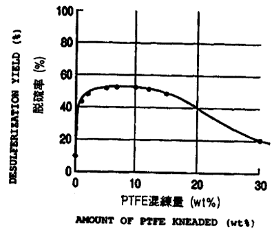
Example 7
Crushed active carbon obtained as in Example 1 was
sorted out in a manner as described above in Example 1.
Then, a commercially available PTFE-dispersed solution
(containing PTFE by 60wt$) was diluted by water to a
PTFE concentration of 2/3 to 1/20 of the original
concentration to obtain diluted PTFE-dispersed
solutions containing PTFE by 3 to 40wt$). Then, lllg
of each of the diluted PTFE-dispersed solutions was
added to 1008 of the above active carbon fine particles
and each of the mixtures was subjected to same
procedures as those of Example 3 (kneading, molding,
drying, rough crushing, sorting) to obtain so many
different specimens of granular active carbon with a
grain diameter between 2.8 and 4.Omm containing PTFE by
0 to 30wt$.
Then, each of the obtained active carbon catalysts
CA 02327591 2000-10-OS
- 44 -
was tested for activity with the method of Example 1.
Table 2 and FIG. 2 show the desulfurization efficiency
of each of the specimens obtained 100 hours after the
start of the test. From the obtained results, it will
be seen that a high desulfurizing rate is achieved when
PTFE is added to active carbon fine particles by 0.5 to
25wt%, preferably 1 to 20wt%, before the mixture is
kneaded.
Table 2
PTFE content desulfurization
(wt%) efficiency (%)
0 10
1 44
2 49
5 52
53
10 54
12 52
15 49
30 20
Example 8
lllg of a diluted PTFE-dispersed solution same as
that of Examples 1 was added to 100g of fine particles
of active carbon obtained as in Example 1 and the
mixture was kneaded in a small crusher (mortar outer
CA 02327591 2000-10-OS
- 45 -
diameter 178mm, lOOrpm, power 100w) for 10 minutes.
Then, the kneaded mixture was subjected to a molding
process under pressure of 500kgf/cm2 to obtain an active
carbon catalyst containing PTFE by lOwt%. Then, the
active carbon catalyst was dried at 45 to 50°C for 12
hours and then roughly crushed and sorted to obtain a
granular active carbon catalyst with a grain diameter
between 2.8 and 4.Omm. Then, the obtained active
carbon catalyst was tested with the test method of
Example 1 to obtain a desulfurization efficiency of
43~.
Example 9
5558 of a diluted PTFE-dispersed solution same as
that of Examples 1 was added to 5008 of fine particles
of active carbon obtained as in Example 1 and mixed in
a V-type bicylinder mixer (capacity 1,OOOmL, 30rpm) for
60 minutes and 1008 of the mixture was kneaded in a
small crusher (mortar outer diameter 178mm, 100rpm,
power 100W) for 10 minutes. Then, the kneaded mixture
is subjected to a molding process under pressure of
500kgf/cm2 to obtain an active carbon catalyst
containing PTFE by lOwt~. Then, the active carbon
catalyst was dried at 45 to 50°C for 12 hours and then
roughly crushed and sorted to obtain a granular active
carbon catalyst with a grain diameter between 2.8 and
4.Omm. Then, the obtained active carbon catalyst was
tested with the test method of Example 1 to obtain a
CA 02327591 2003-06-25
- 46 -
desulfurization efficiency of 43$,
Comparative Example 1
The procedures of Example 1 were followed except
that the ingredients were mixed in a V-type bicylinder
mixer for 60 minutes and visually confirmed that they
had been mixed well instead of manually kneading them
in a mortar. The obtained active carbon catalyst was
tested for activity to find that the desulfurization
efficiency was 18$. This proved that visual
IO confirmation of the extent of mixa_ng is not sufficient
and application of shearing force is necessary to make
the walls of the inter-particulate gaps
water-repellent.
Example 10
A rectangular reaction vessel.. having a cross
section of 35mmx40mm was filled with. a molded catalyst
comprising plate-shaped catalysts arranged triangularly
as shown in FIG. 4A or in parallel as shown in FIG. 4B
(height 900mm, pitch of plate arrangement 2mm). The
molded catalyst had been prepared by mixing powdery
active carbon (coal type,, average particle diameter
30um) and powdery Teflon*(so:Lution dispersed with
particles with average particle diameter of 2,OOOA) to
a ratio of 9:1 and kneading the mixture to mold into a
sheet-shape preform with a thickness of 0.5mm and
applying it to the opposite side of a polypropylene
network with a thickness of 0.3mrn ~;o praduce a
* trade-mark
CA 02327591 2000-10-OS
- 47 -
multilayer product. Then, gas with composition listed
below (45°C) was made to flow through the reaction
vessel filled with the catalyst at different flow
rates.
Oz 4%
COz 10%
Hz0 saturated
SOz 1,OOOppm
Then, the reaction rate y [mol/h] was obtained as the
rate of removing SOz per hour from the difference of the
SOz concentration at the entrance of the reaction vessel
and the corresponding concentration at the exit of the
reaction vessel. Then, the reaction rate constant k
was obtained by means of the formula below.
y - k x Csozn
( Csoz ~ SOz concentration [mol/m3 ] )
(n: constant)
As seen from FIG. 5 showing the results of the
experiments, the reaction rate constant increased as a
function of the flow rate within a range of actual gas
flow rate between 0.5 and 40m/h.
Comparative Example 2
Gas same as that of Example 10 was made to flow
upwardly through a reaction vessel (triangular type)
also same as that of Example 10 at a rate of 30Nm3/h to
determine the reaction rate constant. A value of
3.5x10-' was obtained for k, which represents 730 of its
' CA 02327591 2000-10-OS
- 48 -
counterpart of Example 10 where gas was made to flow
downwardly.
Example 11
Powdery active carbon (coal type, average particle
diameter 30um) and powdery fluororesin (PTFE-dispersed
solution with average particle diameter of 200nm, 60
wt%) were mixed to a ratio of 9:1 and the mixture was
kneaded in a kneader. Thereafter, the kneaded mixture
was molded into a sheet-shape preform with a thickness
of 0.5mm by means of a roll machine. The sheet was
then applied to the opposite sides of a polypropylene
network with a thickness of 0.3mm to produce a
plate-shaped catalyst. A number of similar catalysts
were prepared and some of them were corrugated. Then,
flat plates and corrugated plates were laid alternately
to produce a honeycomb structure as shown in FIG. 6.
Example 12
Powdery active carbon (coal type, average particle
diameter 30pm) and powdery fluororesin (PTFE-dispersed
solution with average particle diameter of 200nm, 60
wt%) were mixed to a ratio of 9:1, to which
methylcellulose was added as additive by lwt% relative
to said active carbon, and the mixture was kneaded in a
kneader. Thereafter, the kneaded mixture was molded
into a sheet-shape preform with a thickness of 0.5mm by
means of a roll machine. The sheet was then applied to
the opposite sides of a polypropylene network with a
CA 02327591 2000-10-OS
- 49 -
thickness of 0.3mm to produce a plate-shaped catalyst.
A number of similar catalysts were prepared and some of
them were corrugated. Then, flat plates and corrugated
plates were laid alternately to produce a honeycomb
structure as shown in FIG. 6.
Example 13
A pair of rectangular reactor vessels having a
cross section of 35mmx40mm were filled with the
respective honeycomb structures obtained in Examples 11
and 12 and gas (45°C) having a composition as shown
below was made to flow therethrough downwardly at a
superficial gas flow rate of 4m/s.
SOz : 800 volume ppm
Oz : 4 volume
COz : 10 volume o
Nz : balance
relative humidity: 100%
Then, the reaction rate y [mol/h] was obtained as the
rate of removing SOz per hour from the difference of the
SOz concentration at the entrance of the reaction vessel
and the corresponding concentration at the exit of the
reaction vessel. Then, the reaction rate constant k
was obtained by means of the formula below.
n
- k x Csoz
( Csoz ~ SOz concentration [mol/m3] )
(n: constant)
As a result, reaction rate constants of 5.2x10⁻⁴ and
CA 02327591 2000-10-OS
- 50 -
5.0x10-' were obtained respectively for the catalysts or
Examples 11 and 12.
Example 14
The active carbon catalyst prepared in Example 1
was tested for its activity in a catalytic
desulfurization reactor. More specifically, a
glass-made reactor with an inner diameter of l6mm and
having a jacket was filled with a 40mL of the active
carbon catalyst and gas with a composition of
SOz: 650 volume ppm
O2: 4 volume %
COz : 10 volume %
Nz : balance
relative humidity: 100%
was made to flow therethrough at a rate of 400L/h at
50°C, while a solution obtained by adding water to the
produced dilute sulfuric acid was made to flow from the
top of the reaction vessel at a rate of 0.2L/h.
Additionally, fly ash (average particle diameter Sum)
obtained from a coal burning power generation plant was
added to the above mixture gas at a rate of 100mg/m3
immediately before the entrance of the reaction vessel.
Then, the SOz concentration was observed at the
exit by means of an SOz meter (UV type) to evaluate the
activity of the catalyst. A sulfur dioxide removal
efficiency of 69% was obtained 100 hours after the
start of the test. After the test, the recovered
' CA 02327591 2000-10-OS
- 51 -
sulfuric acid was filtered to isolate the solid
component (except active carbon and PTFE), the weight
of which was measured. As a result, it was found that
93$ of the supplied fly ash had been removed at the end
of the test continued for 100 hours. The test was
continued for another 1,000 hours. At the end of the
test, it was found that the desulfurizing rate had not
been degraded significantly.