Note: Descriptions are shown in the official language in which they were submitted.
C~
>:~:~;:<~:.1;:.;;1.:',~..9'~..:<. ............ , ....... ....,...............
. =... . . ..
=. . .: .. . .
4 ==. = =.. = = . = = =
= == = = = = = =.== ===
= = = = = = . =
= = = = . . = ~ = =. = = =
i
A method and an apparatus for transfer of pressure
and/or tensile load and an elongate chain for use
therein.
The present invention relates to a method and an
apparatus of making an elongate spindle member having
significant rigidity and stability against pressure
and/or tensile loads as well as bending and torsional
loads, whereby said spindle member acts between two
objects.
According to the invention a transfer of pressure
and/or tensile and possibly torque loads between two
mutually movable objects is provided, which is suitably
applicable for a number of practical purposes and based
on hitherto unknown mechanical principles. Non-exhaus-
tive examples of fields of use aimed at by the inven-
tion may be raising/lowering devices for mutually
height displaceable objects, for instance jacks or
motor-operated lifting devices of any kind, and oper-
ator mechanisms for the opening and closing of windows,
doors and gates.
The method according to the invention comprises
the steps of
- winding-up of a plurality of mutually interlocking
chain links under axial displacement in a helical
winding to form said elongate spindle member,
- using chain links formed with a substantially circu-
lar curvature on their exterior sides and including
associated engagement means,
- drivingly connecting said chain links to a rotatable
driving device arranged in a winding guide means con-
nected with one of said two objects,
- guiding said chain links during rotation of said
driving device in said winding guide means so that the
chain links are interconnected and retained in engage-
ment by their associated engagement means with neigh-
ANiEfvDED':;:;--.
: :=:. :CA 02327694 2000-10-05
. . .. .... . .. .. ..
.. .. . . . .. . . . . . .
~ . . . . . . . . . .. .
. . . . . . . . . ... ...
. . . .. . . . . .
... .... .. ..
2
bouring chain links in the same turn as well as adjac-
ent chain links in neighbouring turns of said elongate
spindle member, and
- coupling the helical winding with the other of said
two objects by means of a cupling member.
By winding mutually interlocked chain links in
this manner in a helical winding under active
retainment of the individual chain links in their
positions in the helical winding, it has turned out to
be possible to provide a spindle device having signifi-
cant stability against pressure and/or tensile loads as
well as bending and torsional loads and which may act
as a pressure bar = or drawbar or torque shaft between
two objects.
According to a preferred embodiment of the method
of the invention a reversibly rotatable driving device
is used, said device increasing by rotation in one
direction of rotation the length of the spindle device
during winding of the chain links in said helical
winding and reduces by rotation in the opposite direc-
tion of rotation the length of the spindle device
during unwinding of the chain links from said helical
winding.
Further embodiments of the method and non-exhaus-
tive examples of its application are described in the
dependent claims 2 - 11.
For carrying out the method the apparatus accord-
ing to the invention is characterized in comprising, in
connection with one of said two objects, a chain
storage with an elongate chain of interlocking chain
links having a substantially circular curvature on
their exterior sides and including associated engage-
ment means, a guide means for advancing the elongate
chain, a winding guide means connected with the advanc-
ing guide means and comprising a guide for engagement
CA 02327694 2000-10-05 AMENDED SHEET
= = .= ...= . == .= ==
== .. . . . == = . . = = .
. . . . = . = = . . = = =
= = = = . = = = . =.= ...
= = . = = = = = = =
= . .. .= ... =.== =. =.
3
with a guide member on the chain links for winding said
helical winding a rotatable driving device arranged in
said winding guide means axial advancement of the
spindle device produced by the helical winding and a
coupling member for coupling the helical winding with
the other of said two objects.
Advantageous embodiments of the apparatus and non-
exhaustive examples of use are described in the depend-
ent claims 13 to 34.
The invention further relates to an elongate chain
comprising interlocking chain links with associated
engagement means for use in the apparatus.
According to the invention the elongate chain is
characterized in each chain link has a substantially
circular curvature on its exterior sides and, in
unfolded projection, substantially the shape of a
parallelogram with a first pair of engagement means for
connection with neighbouring chain links in the same
turn of the helical winding provided at a first pair of
opposite sides and further engagement means for engage-
ment with corresponding engagement means on adjacent
chain links in neighbouring turns of the helical
winding provided at a second pair of opposite sides.
The invention will be explained in the following
by means of an embodiment and with reference to the
partly schematic drawing, in which
Figs 1 and 2 are schematic, perspective views
illustrating the principle of the method according to
the invention,
Figs 3 and 4 show an embodiment of an apparatus
according to the invention,
Fig. 5 shows and embodiment of the apparatus with
integrated chain storage,
Figs 6 and 7 show embodiments of a winding guide
means and a drive means in the apparatus according to
CA 02327694 2000-10-05 ~1~3tNbED SHEET
. . . . . . . . . . . . . . .
.. .. . . . .. . . . . . .
.. . . . .
, . . . . . . .
. . . . . . . . ... ...
. . . . . . . . . .
_ = . . . . . . . . . . . . . 06 . .
3a
Figs 3 and 4,
Figs 8 - 12 show an embodiment of a chain link for
use in the apparatus according to Figs 3 and 4,
Fig. 14 is a perspective view illustrating the
winding up of the interlocking chain links in a helical
winding under mutual retainment,
Fig. 15 is a schematical perspective view of a
first alternative embodiment, in which two spindle
members of equal diameter are formed by individual
helical windings produced from individual sets of chain
links,
Fig. 16 is a schematical sectional view of a
second alternative embodiment, in which two spindle
members of different diameter are formed by individual
helical windings produced from individual sets of chain
links and extending one inside the other,
Fig. 17 is a schematical perspective view of an
alternative embodiment, in which a single spindle
device is formed from two individual sets of chain
links, and
Fig. 18 is a perspective view of the application
of the embodiment shown in fig. 15 in a window operator
device.
As will appear from figs 1 and 2, the invention
resides in its broadest aspect in that chain links 1,
AMENDED SHEET
CA 02327694 2000-10-05
WO 99/53221 PCT/DK99/00171
4
which are mutually interlocked into an elongate chain
2, are wound into a helical winding 5 under mutual
retainment by means of a drive means comprising an
advancing wheel 3 in connection with a drive wheel 4
which may be connected via a transmission with a
preferably reversibly rotatable drive motor (not
shown), and by use of advancing and winding guide
means.
The wound up helical winding thereby forms a
spindle device of variable length and considerable
rigidity and stability against pressure, tensile,
bending and torsional loads.
The winding up of the chain links 1 in the helical
winding 5 takes place during rotation of the drive
wheel 4 in one direction of rotation, the length of the
spindle device being increased under axial advancement
and simultaneous rotation of the helical winding. If
the direction of rotation of the drive wheel 4 is
reversed, the chain links 1 will again become unwound
from the helical winding 5 and the spindle device
formed thereby will be shortened.
When carrying out the method, a chain storage (not
shown in figs 1 and 2) will be provided, together with
advancing and winding guide means (not shown) and the
driving device in connection with one of the two
objects, between which a power transfer is wanted,
preferably a stationary first object, while a second
object movable relative thereto may be connected, as
shown in the intersected view in fig. 2, with the
spindle device 5 by means of a coupling member 6, which
at the start of the winding up of the chain links 1 is
connected with the turn 7 first formed in the helical
winding 5.
As will likewise appear from fig. 2, the spindle
device formed by the helical winding 5 will for many
CA 02327694 2000-10-05
WO 99/53221 PCT/DK99/00171
practical uses be protected by a surrounding, elongate
cover member of variable length, for instance a bellow
8.
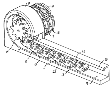
Based on the embodiment shown in figs 3 and 4 of
5 an apparatus according to the invention examples of the
design of the individual components of the apparatus
will be explained in the following.
In the embodiment shown in figs 3 and 4, the
mutually interlocked chain links 12 are advanced in an
elongate chain 11 from a chain storage (not shown) by
means of a substantially linear advancing guide member
13 towards a winding guide member 14, in which the
drive means with the drive wheel 15 and the advancing
wheel (not shown) are journalled by means of bearing
means (not shown).
By clockwise rotation of the drive wheel 15, the
chain links 12 are wound, guided by the winding guide
means 14, in the helical winding 16, in which the chain
links 12 are positioned in closely packed turns 17
under mutual retainment, such that the wound up chain
links are prevented from mutual displacement in the
helical winding.
In the winding guide means 14, the chain links 12
first arriving are brought into engagement with a
coupling member 18 shown in fig. 3. While the advancing
guide means 13, the winding guide means 14 and the
drive means with the drive wheel 15 are placed in
connection with one of the two objects, between which
pressure and/or tensile as well as torque loads are to
be transferred by means of the apparatus, the coupling
member 18 serves for connecting the spindle device 16
with the other of the two objects. The drive means may
alternatively, together with the coupling member, be
positioned in connection with the second object.
Fig. 5 shows, in a schematic plane view, how the
CA 02327694 2000-10-05
WO 99/53221 PCT/DK99/00171
6
winding up guide means 14 and the advancing guide means
13 may be integrated in a common housing 9 with a chain
storage in the shape of a track 10, in which the
elongate chain 11 is received in its entire length.
The advancing guide means 13 is in the embodiment
shown designed as a linear rail member with a bottom
surface 19 forming an elongate advancing guide surface
for a convex exterior side of the interlocked chain
links 12, and a superjacent guide rail 20 which by
engagement with engagement means at a concave interior
side of the chain links 12 guides them safely towards
the winding up guide means 14.
The winding up guide means 14 is in the embodiment
shown in fig. 6 formed with a substantially part-
cylindrical wall 21, on the interior side of which a
winding guide is formed by a thread-rib 22, which in
the embodiment shown extends with a predetermined pitch
across slightly more than 360 of the interior periph-
ery of the wall 21. At one end 23 of the thread-rib 22,
the interior side of the part-cylindrical wall 21 joins
in a tangential plane in an extension 24 of the advanc-
ing guide surface 19. An advancing guide means 25 in
the form of a protruding member for engagement with a
track in the exterior side of the chain links 12 is
connected with the advancing guide surface 24. This
will be explained in detail in the following.
In the embodiment of the drive means shown in fig.
7, the drive means 15 is connected with an advancing
wheel 26 which is provided, in a peripheral surface,
with a number of oblique teeth with a predetermined
pitch directed oppositely to the pitch of the threaded
groove 22 on the interior side of the cylindrical wall
21 in the winding guide means 14. As will be explained
in detail in the following, the advancing wheel 26 with
the teeth 27 engages, during winding up of the chain
CA 02327694 2000-10-05
WO 99/53221 PCT/DK99/00171
7
links 12, a helical track in the interior side of the
chain links 12 and thereby brings about an axial
advancement of the helical winding provided during
winding-up under simultaneous rotation of the helical
winding about its axis.
As will be seen from the projected view in fig.
12, the individual chain links 12 have, in an unfolded
projection, substantially the shape of a parallelogram
with a first pair of opposite sides 28 and 29 and a
second pair of opposite sides 30 and 31.
As more clearly seen in figs 8 - 11 the chain
links 12 have a substantially circular curvature with
a convex exterior side 32 and a concave interior side
33, such that, when wound up, the chain links 12 form
the substantially circular-cylindrical helical winding
16. To prevent joints between chain links 12 in the
individual turns 17 in the helical winding 16 from
being positioned diametrally opposite one another, the
chains 12 have a length differing from an even circle
fraction, preferably with an odd number of chain links
12 in each turn depending on the desired dimensions of
the helical winding made. In practice, 5 chain links
per turn have proved suitable for many purposes, such
as will be most clearly seen from figs. 5 and 14.
For engagement with the winding guide in the
winding guide means 14 formed by the thread-rib 22, a
substantially linear track 34 is provided as a guide
member in the convex exterior side 32 of each chain
link, said track forming with the first pair of oppo-
site sides 28 and 29 an angle v determined by the pitch
angle of the thread-rib 22 relative to the axis of the
part-cylindrical wall 21 of the winding guide means 14.
For engagement with the member 25 protruding as an
advancing guide member from the extension 24 of the
advancing guide surface, each chain link 12 comprises
CA 02327694 2000-10-05
WO 99/53221 PCT/DK99/00171
8
in the convex exterior side 32 as a second guide member
a track 35 with two axially displaced track portions
35a and 35b which in each of a first pair of opposite
sides 28 and 29 of the chain link 12 end in track
orifices 36, 37 displaced in a direction parallel with
the sides 28, 29. This design of the track brings each
chain link 12 from the advancing guide surface 19, 24
into the winding guide means 14 with an axial displace-
ment component and the orifice 38 of the track 34 at
the downstream side 28 in the advancing direction, will
be orientated against and aligned with the inlet end 23
of the thread-rib 22.
For engagement with the oblique teeth 27 on the
advancing wheel 26 in the embodiment shown, a helical
track 39 is provided in the concave interior side 33 of
each chain link, as shown in Figs 10 and 11, said track
being in the embodiment shown oriented substantially
diagonally between track orifices 40 and 41 in each of
the second pair of opposite sides 30 and 31. This form
of the track has the effect that in the interior side
of the wound up helical winding, a number of continu-
ous, coherent helical tracks 42 is formed for engage-
ment with each theirs of the corresponding number of
oblique teeth 27 on the advancing wheel 26. If the
drive means is alternatively connected with the coup-
ling member 18, the interior tracks 39 may be dispensed
with. Thereby, the chain links may ultimately be formed
so as to substantially close the internal cavity of the
spindle device to improve the rigidity and stability
thereof.
For retaining the individual chain links 12 in
their mutual positions in the turn 17 of the helical
winding 16, each chain link 12 is provided with various
pairs of co-operating engagement means.
Thus, a first pair of co-operating engagement
CA 02327694 2000-10-05
_ . ....._ _ .....,...,..w......... .~...wõ.............. ,_
WO 99/53221 PCT/DK99/00171
9
means for connecting each chain link 12 with its
neighbouring chain links comprises a curved track 43
and a hook-shaped hinge member 44 at each of the first
pair of opposite sides 28 and 29 of the chain link. The
shape of the track 43 and the hinge member received
therein are adapted to one another and the track 43 has
a depth, such that, in the wound up helical winding 16,
the hinge member is pushed completely into the groove
43, as shown in Fig. 14.
A second pair of co-operating engagement means
comprises a fork member 45 provided in the interior
wall 46 of the curved track 43 and a rib member 47
provided at the interior side of the hook-shaped hinge
member 44. By the engagement of the fork and rib
members 45 and 47 with a rib member 47 and a fork
member 45, respectively, on each of neighbouring chain
links in the same turn, neighbouring chain links in the
same turn 17 are prevented from mutual displacement in
the axial direction of the helical winding produced.
On the interior side of the hook-shaped hinge
member 44 abutment surfaces 48 for the branches 45a of
the fork member 45 are further provided. Through the
abutment of the fork branches 45a against the surfaces
48, the winding movement of the chain link 12 is
stopped, such that neighbouring chain links in the same
turn 17 are retained in their mutual angular position,
which is determined by the number of chain links in the
turn.
As shown in fig. 3 the fork member 45 further
serves as engagement member for the guide rail 20 in
the advancing guide means 13.
As will appear from figs 10; 11 and 14 the fork
and rib members 45 and 47 on each chain link 12 are
further axially displaced relative to one another.
Hereby is attained that the curved track 43 in the
CA 02327694 2000-10-05
WO 99/53221 PCT/DK99/00171
entrance side 28 of each chain link at the winding in
the helical winding, in addition to maintaining its
engagement with the hook-shaped hinge member 44 on the
previously introduced chain link 12, is brought into
5 overlapping engagement with the hook-shaped hinge
member 44 on the chain link in the turn formed immedi-
ately prior thereto in the helical winding 16, which is
adjacent to this previously introduced chain link. This
engagement has the effect that neighbouring turns 17 in
10 the helical winding 16 are retained against mutual
displacement in a plane perpendicular to the axial
direction.
Finally, each of the chain links 12 is provided,
at each of the second pair of opposite sides 30 and 31,
with further engagement means which comprise a track 49
in the convex exterior side 32 of the chain link and a
rib member 50 along one and the other side 30 and 31,
respectively. By engagement of the track 49 and the rib
member 50 with corresponding engagement means on
adjacent chain links in neighbouring turns is ensured,
by the winding-up of the chain links 12 in the helical
winding, that chain links in neighbouring turns posi-
tioned side by side are secured in mutual engagement.
The coupling member 18, with which the winding 17
first formed in the helical winding 16 is connected
during the winding up of the chain link 12, is in the
embodiment shown in Fig. 13 designed as a substantially
disc-shaped cover member with a substantially circular-
cylindrical edge surface 51, in which a track 52 is
provided as a guide member for engaging the thread-rib
22 in the winding guide means 14, said track being
substantially identical to the track 34 in the convex
exterior side 32 of each chain link.
On the side surface 53 facing the helical winding
16, the coupling member 18 is provided with a number of
CA 02327694 2000-10-05
WO 99/53221 PCT/DK99/00171
11
protruding engagement means 54 corresponding to the
number of chain links 12 in each turn of the helical
winding 16, the height of said protruding engagement
means 54 from side surface 53 increasing in accordance
with the pitch of the wound up helical winding 16.
As the chain links 12, as mentioned above, are
introduced in the winding guide means 14 with the side
28 with the curved track 43 in front and the side 31
with the rib member 50 facing outwards towards the
coupling member 18, each of the engagement means 54 is
provided with a hook-shaped hinge member 55 correspon-
ding to the hook-shaped hinge member 44 on each chain
link 12 and with an engagement track 56 for engagement
with the rib member 50 on a chain link in the turn
first formed.
By providing the chain links 12 and the coupling
member 18 with the described co-operating engagement
means, the chain links 12 will be safely secured and
locked relative to each other in the wound up helical
winding 16, which then together with the coupling
member 18 provides a spindle device having considerable
rigidity and high stability towards pressure and
tensional load as well as towards bending, torsional
and torque loads.
In fig. 15 an embodiment of the method an appar-
atus of the invention is illustrated, by which two
spindle devices 57 and 58 are formed in linear exten-
sion of each other by winding-up chain links 59 and 60,
respectively, from individual chains in separate
helical windings having the same diameter. By provision
of individual advancing guide means and winding guide
means for the two spindle devices 57 and 58 at one and
the other of the two objects to be interconnected, the
chain storage needed to produce a given maximum length
of the total spindle device may be evenly distributed
CA 02327694 2000-10-05
WO 99/53221 PCT/DK99/00171
12
between the two objects.
In each helical winding the first produced turn 61
and 62, respectively, is connected with a coupling
member 63 and 64, respectively, which coupling members
are connected with each other intermediate the two
objects, which are not shown in fig. 15.
The pitch direction of the helical windings of the
two spindle devices 57 and 58 are opposite as illus-
trated by arrows 65 and 66, respectively, so that for
the two opposite directions of revolution the length of
both spindle devices 57 and 58 will either increase or
decrease at the same time.
Fig. 16 shows another alternative embodiment, in
which one spindle device 67 of two individual spindle
devices 67 and 68 having opposite pitch directions to
function in the same way as escribed above, is formed
is formed with an external threading 69 engaging an
internal threading 70 formed by the helical track in
the interior side of the chain links of the other
spindle device 68.
Also in this case, the advancing and winding guide
means 71 and 72, respectively, for the helical windings
of spindle devices 67 and 68 are provided at one and
the other of the two objects 73 and 74 constituting
e.g. main frame and sash members of an openable window,
respectively, whereas each of spindle devices 67 and 68
functions as a coupling member for the other spindle
device, so that separate coupling members for the first
produced turn of each spindle device are dispensed
with. By the simultaneous winding.-up of the two spindle
devices 67 and 68 from one and the other of the two
objects, the spindle device 67 will simply gradually be
screwed into the spindle device 68.
By this arrangement the rigidity and stability of
the overall spindle resulting from the combination of
CA 02327694 2000-10-05
WO 99/53221 PCT/DK99/00171
13
the individual spindle devices 67 and 68 is further
increased.
Fig. 17 shows a further alternative embodiment, in
which a single spindle device 75 is formed by winding-
up two separate individual sets of chain links 76 an 77
in alternating turns of the helical winding. The two
chains comprising links 76 and 77, respectively, are
advanced towards a common winding guide means (not
shown) of the same principal construction as shown in
figs. 3 and 4 so as to enter the part cylindrical wall
of the winding guide means at two points that are
preferably diametrically opposite to each other.
Compared to the embodiments described hereinbefore the
winding guide means must have an internal threaded rib
for each of the separate sets of chain links 76 and 77,
each of said threaded ribs having a pitch and the form
of the external tracks in the chain links corresponding
to tracks 34 and 35 i figs. 8 and 9 being dimensioned
to impart an axial displacement component to the chain
links entering the winding guide means sufficient to
allow the winding-up of chain links 72 and 73 in
alternating turns.
By this alternating turn design of the spindle
device the chain supply needed to produce a spindle
device of a given length can be divided into two
separate chains arranged on either side of the winding
guide means. By use of the apparatus in a window
operator this design will facilitate arrangement of the
operator housing including the winding guide means in
the middle of a main frame or sash member.
Fig. 18 shows an example of application of the
embodiment schematically illustrated in fig. 15 in an
operator device for a window having a main frame 78 and
an openable sash 79, which are pivotally connected with
each other by hinge means (not illustrated) provided at
CA 02327694 2000-10-05
WO 99/53221 PCT/DK99/00171
14
opposed bottom members 80 and 81 of the main frame and
sash structures. Operator housings 82 and 83 arranged
on opposed top members 84 and 85 of the main frame and
sash structures accommodate a chain storage with asso-
ciated advancing guide means, winding guide means and
drive means for the winding-up of chain links from each
chain in the helical windings forming the two spindle
devices 57 and 58, which are connected end by end by
means of the coupling members 63 and 64.
It is within the scope of the invention possible
to design the individual components of the apparatus in
other ways. The number of chain links in each turn in
the helical winding will thus depend on the dimensions
of the spindle device suitable for the purpose in
question. The coupling member connecting the spindle
device with the second one of the two objects to be
connected, may be connected with the helical winding in
other ways, for instance as shown in Fig. 2 with a
bushing member, fastened in the interior of the helical
winding. Also the chain links may be designed in other
ways, provided the functional conditions in respect of
winding, axial advancement in the helical winding and
mutual securing be met, the object of said conditions
being to prevent relative movement between the individ-
ual chain links and between individual turns in the
helical winding.
CA 02327694 2000-10-05