Language selection

Search

Patent 2327965 Summary

Third-party information liability

Some of the information on this Web page has been provided by external sources. The Government of Canada is not responsible for the accuracy, reliability or currency of the information supplied by external sources. Users wishing to rely upon this information should consult directly with the source of the information. Content provided by external sources is not subject to official languages, privacy and accessibility requirements.

Claims and Abstract availability

Any discrepancies in the text and image of the Claims and Abstract are due to differing posting times. Text of the Claims and Abstract are posted:

  • At the time the application is open to public inspection;
  • At the time of issue of the patent (grant).
(12) Patent: (11) CA 2327965
(54) English Title: HAIRBRUSH HAVING A BRUSH SEAT PROVIDED WITH SLIDABLE BRISTLES THERETO
(54) French Title: BROSSE A CHEVEUX MUNIE D'UN FOND A SOIES COULISSANTES
Status: Expired
Bibliographic Data
(51) International Patent Classification (IPC):
  • A46B 3/00 (2006.01)
  • A46B 7/06 (2006.01)
(72) Inventors :
  • WANG, HUO-PIA (Taiwan, Province of China)
(73) Owners :
  • WANG, HUO-PIA (Taiwan, Province of China)
(71) Applicants :
  • WANG, HUO-PIA (Taiwan, Province of China)
(74) Agent: OYEN WIGGS GREEN & MUTALA LLP
(74) Associate agent:
(45) Issued: 2005-01-11
(22) Filed Date: 2000-12-08
(41) Open to Public Inspection: 2002-06-08
Examination requested: 2001-11-30
Availability of licence: N/A
(25) Language of filing: English

Patent Cooperation Treaty (PCT): No

(30) Application Priority Data: None

Abstracts

English Abstract

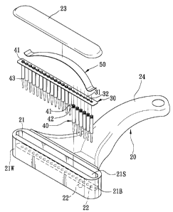
A hairbrush includes a handle body formed with a hollow brush seat on one end. The brush seat has a bottom wall, and defines a bristle accommodating space above the bottom wall. The bottom wall is formed with a row of bristle holes therethrough. A flexible bristle retention member is disposed on the bottom wall inside the bristle accommodating space. Each of a plurality of bristles has a head portion connected to the bristle retention member, a middle portion that passes slidably through a respective one of the bristle holes, and a tip portion disposed outwardly of the bristle accommodating space.


French Abstract

Brosse à cheveux incluant un corps de manche formé d'un siège de brosse creux sur une extrémité. Le siège de brosse comprend une paroi de base et définit un espace de logement de crins au-dessus de la paroi de base. La paroi de base est formée d'une rangée de trous de crins à travers celle-ci. Un élément de rétention de crin souple est disposé sur la paroi de base à l'intérieur de l'espace de logement de crins. Chaque crin de la pluralité de crins comprend une portion de tête raccordée à l'élément de rétention de crin, une portion médiane qui passe avec faculté de glissement à travers un trou respectif des trous de crins, et une portion de pointe disposée vers l'extérieur de l'espace de logement de crins.

Claims

Note: Claims are shown in the official language in which they were submitted.


7
I CLAIM:
1. A hairbrush comprising:
a handle body formed with a hollow brush seat on one
end, the brush seat having a bottom wall and defining a
bristle accommodating space above the bottom wall, the
bottom wall being formed with a row of bristle holes
therethrough;
a flexible bristle retention member disposed on the
bottom wall inside the bristle accommodating space,
said bristle retention member being formed as a
flexible plate having a longitudinal slit, and a
plurality of bristle retaining holes disposed along the
slit and aligned respectively with the bristle holes of
the bottom wall; and
a plurality of bristles, each of which has a head
portion connected to the bristle retention member, a
middle portion passing slidably through a respective
one of the bristle holes, and a tip portion disposed
outwardly of the bristle accommodating space.
2. The hairbrush as defined in Claim 1, wherein each of
the bristle retaining holes has a hole-confining
periphery, and the head portion of each of the bristles
is formed with a retaining groove for engaging the
bristle retention member at the hole-confining
periphery of a respective one of the bristle retaining


8
holes.
3. The hairbrush as defined in Claim 1, wherein the
brush seat further has a looped surrounding wall that
extends upwardly from a periphery of the bottom wall so
as to confine the bristle accommodating space
therewith, and a top cover mounted on an upper end of
the surrounding wall opposite to the bottom wall to
close the bristle accommodating space.
4. The hairbrush as defined in Claim 3, further
comprising a biasing unit disposed in the bristle
accommodating-space for biasing the bristles to extend
outwardly of the bristle accommodating space.
5. The hairbrush as defined in Claim 4, wherein the
biasing unit includes a curved leaf spring having a
convex intermediate portion that abuts against the top
cover, and two distal end portions that press the
bristle retention member against the bottom wall.
6. The hairbrush as defined in Claim 4, wherein the
biasing unit includes a resilient block having an upper
portion that abuts against the top cover, and a lower
portion that presses the bristle retention member
against the bottom wall.
7. The hairbrush as defined in Claim 6, wherein the
resilient block is made from rubber.


9
8. The hairbrush as defined in Claim 6, wherein the
resilient block is made from a sponge material.
9. The hairbrush as defined in Claim 4, wherein the
biasing unit includes a plurality of coiled springs,
each of which has an upper end that abuts against the
top cover, and a lower end that presses the bristle
retention member against the bottom wall.

Description

Note: Descriptions are shown in the official language in which they were submitted.


CA 02327965 2004-03-05
1
TITLE: HAIRBRUSH HAVING A BRUSH SEAT PROVIDED WITH
SLIDABLE BRISTLES THERETO
FIELD OF THE INVENTION
The invention relates to a hairbrush, more
particularly to a hairbrush which has a brush seat
provided with a plurality of slidable bristles thereto.
BACKGROUND OF THE INVENTION
Referring to Figures 1 and 2, which illustrate
prior art, a conventional hairbrush 10 is shown to
include a handle body 13 with a brush seat 11 at one
end thereof, and a plurality of bristles 12.
As illustrated, the brush seat 11 is formed with a
bottom portion 1B. Each of the bristles 12 has a
connecting portion 12C connected securely to the bottom
portion 11B of the brush seat 11, and a combing portion
12B extending away from the bottom portion 11B.
A drawback of the aforethe conventional hairbrush
arises when combing hair. Because the length of the
bristles 12 is fixed, the bristles 12 that are located
on two lateral sides of the hairbrush 10 can not fully
reach the scalp 14 such that the user will have a j=eeling
that his/her hair is not thoroughly brushed.
SUN~tARY OF THE INVENTION
The object of this invention is to provide a
hairbrush which is clear of the aforesaid drawback that

CA 02327965 2004-03-05
2
generally results from the use of the conventional
hairbrush.
Accordingly, the hairbrush of the present invention
includes a handle body, a flexible bristle reten=ion
member, and a plurality of bristles. The handle bode is
formed with a hollow brush seat on one end. The brush
seat has a bottom wall, and defines a brig>tle
accommodating space above the bottom wall. The botaom
wall is formed with a row of bristle hales
therethrough. The bristle retention member is disposed
on the bottom wall inside the bristle accommodating
space. Each of the bristles has a head portion
connected to the bristle retention member, a middle
portion that passes slidably through a respective one
of the bristle holes, and a tip portion disposed
outwardly of the bristle accommodating space.
BRIEF DESCRIPTION OF THE DRAWINGS
Other features and advantages of this invention
will become more apparent in the following detailed
description of the preferred embodiments of this
invention, with reference to the accompanying drawings, in
which:
Figure 1 is a perspective view of a conventional
hairbrush;
Figure 2 is a schematic view illustrating t:he

CA 02327965 2004-03-05
3
conventional hairbrush in a state of use;
Figure 3 is a perspective view of the first
preferred embodiment of a hairbrush of the present
invention;
Figure 4 is an exploded perspective view of the
first preferred embodiment;
Figure S is a sectional view of the first preferred
embodiment;
Figures 6(A) and 6(B) are sectional views of the
first preferred embodiment in first and .second
conditions of use;
Figure 7 is a sectional view of the :second
preferred embodiment of the present invention when in
use; and
Figure 8 is a sectional view of the third prei:erred
embodiment of the present invention when in use.
DEVILED DESCRIPTION OF THE PREFERRED EMBODIMENTS
Referring to Figures 3,4 and 5, the first preferred
embodiment of a hairbrush 20 of the present invention
is shown to include a handle body 24, a bristle
retention member 30, and a plurality of bristles 40.
As illustrated, the handle body 24 is formed w_Lth a
hollow brush seat 21 on one end. The brush seat 21
has a bottom wall (21B), and defines a bristle
accommodating space (21S) above the bottom wall (21B).

CA 02327965 2004-03-05
4
The bottom wall (21B) is formed with a row of bristle
holes 22 therethrough.
The bristle retention member 30 is formed as an
elongated flexible thin plate. The retention member 30
is disposed on the bottom wall (21B) inside the bristle
accommodating space (21S) .
Each of the bristles 40 has a head portion 41
connected to the bristle retention member 30, a middle
portion 44 that passes slidably through a respective
one of the bristle holes 22, and a tip portion 43
disposed outwardly of the bristle accommodating space
(21S) .
The bristle retention member 30 is formed wit~~ a
longitudinal slit 31, and a plurality of bristle
retaining holes (32) disposed along the slit 31 and
aligned respectively with the bristle holes 22 in the
bottom wall (21B). Each of the bristle retaining holes
32 has a hole-confining periphery. The head portion 41
of each of the bristles 40 is formed with a retaining
groove 42 for engaging the bristle retention member 30
at the hole-confining periphery of a respective one of
the bristle retaining holes 32.
The brush seat 21 further has a looped surround,'~ng
wall (21W) (see Fig. 4) that extends upwardly from a
periphery of the bottom wall (21B) so as to confine t:he

CA 02327965 2004-03-05
bristle accommodating space (21S) therewith, and a top
cover 23 mounted on an upper end of the surrounding wall
(21W) opposite to the bottom wall (21B) via known high
frequency sealing techniques so as to close the bristle
5 accommodating space (21S).
A biasing unit 50 is disposed in the bristle
accommodating space (21S) for biasing the brist:Les 40
to extend outwardly of the bristle accommodating space
(21S). The biasing unit 50 includes a curved leaf
spring having a convex intermediate portion 501. that
abuts against the top cover 23, and two distal end
portions 502 that press the bristle retention member 30
against the bottom wall (21B). Alternatively, in
another preferred embodiment, the biasing unit can be a
resilient block 60 (see Figure 7) , such as rubber,
which has an upper portion 601 that abuts against the
top cover 23, and a lower portion 602 that presses the
bristle retention member 30 against the bottom wall
(21B) . The resilient block 60 can also be made from a
sponge material.
In a further preferred embodiment, the biasing unit
can be a plurality of coiled springs 70 (see Figure 8),
each of which has an upper end that abuts against the
top cover 23, and a lower end that presses the bristle
retention member 30 against the bottom wall (21S).

CA 02327965 2004-03-05
6
As best illustrated in Figures 6(A), 6(B), 7 and 8,
since the bristles 40 are slidable relative to the
bottom wall 21B of the brush seat 21, and since the
bristle retention member 30 is flexible, the tip
portions 43 of the bristles 40 can conform with the
outline of the scalp so that hair can be thoroughly
brushed.

Representative Drawing
A single figure which represents the drawing illustrating the invention.
Administrative Status

For a clearer understanding of the status of the application/patent presented on this page, the site Disclaimer , as well as the definitions for Patent , Administrative Status , Maintenance Fee  and Payment History  should be consulted.

Administrative Status

Title Date
Forecasted Issue Date 2005-01-11
(22) Filed 2000-12-08
Examination Requested 2001-11-30
(41) Open to Public Inspection 2002-06-08
(45) Issued 2005-01-11
Expired 2020-12-08

Abandonment History

There is no abandonment history.

Payment History

Fee Type Anniversary Year Due Date Amount Paid Paid Date
Application Fee $150.00 2000-12-08
Request for Examination $200.00 2001-11-30
Maintenance Fee - Application - New Act 2 2002-12-09 $50.00 2002-09-11
Maintenance Fee - Application - New Act 3 2003-12-08 $50.00 2003-10-15
Maintenance Fee - Application - New Act 4 2004-12-08 $50.00 2004-10-18
Final Fee $150.00 2004-10-27
Maintenance Fee - Patent - New Act 5 2005-12-08 $100.00 2005-10-17
Maintenance Fee - Patent - New Act 6 2006-12-08 $100.00 2006-10-13
Maintenance Fee - Patent - New Act 7 2007-12-10 $100.00 2007-10-17
Maintenance Fee - Patent - New Act 8 2008-12-08 $100.00 2008-09-19
Maintenance Fee - Patent - New Act 9 2009-12-08 $100.00 2009-09-11
Maintenance Fee - Patent - New Act 10 2010-12-08 $125.00 2010-10-29
Maintenance Fee - Patent - New Act 11 2011-12-08 $125.00 2011-12-05
Maintenance Fee - Patent - New Act 12 2012-12-10 $125.00 2012-08-06
Maintenance Fee - Patent - New Act 13 2013-12-09 $125.00 2013-07-31
Maintenance Fee - Patent - New Act 14 2014-12-08 $125.00 2014-08-14
Maintenance Fee - Patent - New Act 15 2015-12-08 $225.00 2015-08-12
Maintenance Fee - Patent - New Act 16 2016-12-08 $225.00 2016-09-07
Maintenance Fee - Patent - New Act 17 2017-12-08 $225.00 2017-08-08
Maintenance Fee - Patent - New Act 18 2018-12-10 $225.00 2018-09-12
Maintenance Fee - Patent - New Act 19 2019-12-09 $225.00 2019-08-05
Owners on Record

Note: Records showing the ownership history in alphabetical order.

Current Owners on Record
WANG, HUO-PIA
Past Owners on Record
None
Past Owners that do not appear in the "Owners on Record" listing will appear in other documentation within the application.
Documents

To view selected files, please enter reCAPTCHA code :


To view images, click a link in the Document Description column. To download the documents, select one or more checkboxes in the first column and then click the "Download Selected in PDF format (Zip Archive)" or the "Download Selected as Single PDF" button.

List of published and non-published patent-specific documents on the CPD .

If you have any difficulty accessing content, you can call the Client Service Centre at 1-866-997-1936 or send them an e-mail at CIPO Client Service Centre.


Document
Description 
Date
(yyyy-mm-dd) 
Number of pages   Size of Image (KB) 
Cover Page 2002-06-07 1 39
Claims 2000-12-08 3 76
Drawings 2000-12-08 9 197
Description 2000-12-08 5 170
Representative Drawing 2002-05-13 1 12
Abstract 2000-12-08 1 20
Description 2004-03-05 6 162
Claims 2004-03-05 3 72
Cover Page 2004-12-14 1 40
Assignment 2000-12-08 2 81
Prosecution-Amendment 2001-11-30 1 47
Prosecution-Amendment 2004-01-28 3 91
Prosecution-Amendment 2004-03-05 11 300
Correspondence 2004-10-27 2 70
Fees 2010-10-29 1 199
Correspondence 2007-09-06 2 74
Maintenance Fee Payment 2018-09-12 1 33
Fees 2016-09-07 1 33