Note: Descriptions are shown in the official language in which they were submitted.
CA 02327981 2000-12-08
Ackerman 25-24-29-44
A METHOD AND APPARATUS TO SELECT OPTIMAL
OPERATING CONDITIONS IN A DIGITAL WAVELENGTH
STABILIZED CONTROL SYSTEM
Field Of The Invention
s This invention relates to semiconductor lasers and more specifically to a
control system for selecting optimal operating conditions in multichannel
laser sources.
Background Of The Invention
An ever increasing need for information transmission has led to an
increase in optical transmission systems. Optical transmission sources, such
as lasers are
becoming more and more complex. Recent advances in wavelength division
multiplexing
(WDM) and dense wavelength division multiplexing (DWDM) require accurate
wavelength lasers that are capable to function in mufti-channel transmission
arrangements.
In a dense wavelength division multiplexed optical network, multiple
~ 5 channels of different frequency or wavelength are coupled to a single
optical fiber so as
to increase the information capacity carried through the system. The channel
density of
such networks has increased dramatically resulting in narrower frequency
spacing
between channels. The frequency or channel spacing is narrowing from a typical
100
GHz range to about 50 GHz and even 25 GHz range.
2o One family of semiconductor laser that is used in such mufti-channel
transmission arrangements is known as distributed Bragg reflector laser (DBR),
which is
capable of generating a plurality of lights with desired wavelengths with a
narrow
channel spacing. A DBR laser has a laser cavity situated between two
reflective
surfaces. A tuning current signal is provided to one or both reflective
surfaces to change
25 the index of refraction, which in turn varies the wavelength of the laser
light generated
by the DBR.
In a multichannel laser system such as one that employs a DBR laser, it is
CA 02327981 2000-12-08
Ackerman 25-24-29-44 2
important to control laser side mode suppression ratio (SMSR) at a desired
level, so as
to prevent cross-talk and transmission error. Typically, for each channel of
the DBR
laser a ratio of -30 to -40 dB suppression is necessary for ensuring proper
transmission.
However, within each desired channel, there are tuning current signal values
that can
cause the suppression ratio to decrease dramatically. As such, prior art
systems do not
typically use DBR lasers in order to vary laser wavelength. Rather, a
plurality of
distributed feedback, DFB, lasers are employed, with each one tuned to a
desired
wavelength.
Some prior art systems that have attempted to control laser side mode
1o suppression ratio (SMSR) employ analog techniques based on generating a
second
harmonic tone from an analog tone that is superimposed onto the laser drive
current.
This technique may cause transmission errors in certain applications, and
therefore is not
desirable.
Thus, there is a need for a control system for a multichannel laser source,
15 such as a DBR laser, that maintains a desired operating point within each
wavelength
channel.
Summary Of The Invention
In accordance with one embodiment of the invention, a control system in
a multichannel laser controls the tuning current provided to the laser source
by
2o measuring the slope values of laser power as a function of tuning current.
The laser
power may be measured at its front face, where the generated light is directed
to an
optical fiber, or in the alternative, may be preferably measured at its back
face, where
portion of the emitted light can be measured. The tuning current is then
varied until the
system measures a desired slope value. The desired slope value relates to an
area of the
25 curve, representing the laser power, preferably backface power, versus
tuning current,
that assures an acceptable laser side mode suppression ratio, or other optimal
operating
parameters. In accordance with another embodiment of the invention, the
control system
CA 02327981 2000-12-08
Ac~erman 25-24-29-44 3
also ensures that the laser source is operating so as to provide a desired
frequency.
In accordance with another embodiment of the invention, a
microprocessor-based control system is employed. A look-up table stores all
desired
slope values for each operating channel. The desired slope values are measured
in
advance, based on the characteristics of the laser source. Thereafter, an
optical
discriminator is employed to provide the laser power source value and the
frequency of
the light source to the microprocessor. The microprocessor provides an
increment in
tuning current over several iterations, so that the average slope values of
the laser
backface power source is calculated. The system then determines which value of
tuning
1o current corresponds to a slope closest to the look-up table slope value for
a specified
channel, and slowly steps the tuning current to the desired value.
The control system in accordance with the present invention allows
multichannel optical laser sources, such as DBR lasers to operate flexibly
over a wide
range of available channels, while avoiding operating points that experience
low side
~ 5 mode suppression ratio or other undesired operating parameters.
Brief Description Of The Drawings
The subject matter regarded as the invention is particularly pointed out
and distinctly claimed in the concluding portion of the specification. The
invention,
however, both as to organization and method of operation, together with
features,
20 objects, and advantages thereof may best be understood by reference to the
following
detailed description when read with the accompanying drawings in which:
Fig. 1 illustrates a plot of laser wavelengths and laser back face current as
a function of tuning current in a distributed Bragg reflective (DBR) in
accordance with
one embodiment of the present invention.
2s Fig. 2 illustrates, a plot of laser power output values as a function of
tuning current within one of the operating channels illustrated in Fig. 1 in
accordance
with one embodiment of the present invention.
CA 02327981 2000-12-08
Ackerman 25-24-29-44 4
Fig. 3 illustrates a block diagram of a DBR laser control system in
accordance with one embodiment of the present invention.
Fig. 4 illustrates a flow chart of a control system for operating a DBR
laser in accordance with one embodiment of the present invention.
Fig. 5 illustrates a combined operation of a temperature control loop and
a tuning current control loop in accordance with one embodiment of the present
invention.
Detailed Description Of The Drawings
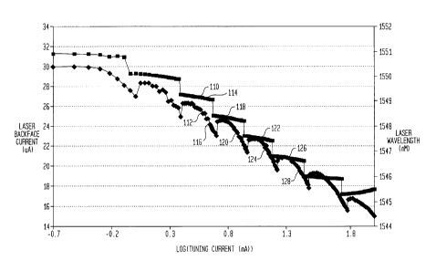
Fig. 1 illustrates two plots 110 and 112 that relate to the characteristics of
to a distributed Bragg reflective (DBR) laser in accordance with one
embodiment of the
present invention. As illustrated plot 110 represents laser wavelength values
as a
function of a tuning current on a log scale. The DBR laser exhibiting the
characteristics
illustrated in Fig. 1 provides laser beams with relatively fixed wavelengths
for a specified
range of tuning current. Thus, step 114 of curve 110 represents one channel of
the laser
t s source, which corresponds to a relatively fixed wavelength, for example,
around 1549
nm. Step 118 of curve 110 represents another channel of the laser source,
which
corresponds to a relatively fixed wavelength, for example, around 1548 nm.
Similarly,
steps 122 and 126 of curve 110 represent other channels of the laser source,
which
respectively correspond to a relatively fixed wavelength for example, around
1547nm
20 and 1546 nm.
As the tuning current changes, the wavelength of the light source varies
also. The wavelength variation within each channel is relatively small,
whereas the
variation from one channel to the other is more significant. In accordance
with one
embodiment of the invention, a control system for generating a desired tuning
current
25 provides for the operation of the laser source at specified locations along
each channel
defined by plot 110. These specified locations may be advantageously selected
so as to
decrease transmission errors, such as bit error rate, dispersion, and
frequency chirp, as
CA 02327981 2000-12-08
Ackerman 25-24-29-44 5
well as to increase side mode suppression to acceptable levels. The dynamic
shift of
lasing frequency, under modulation, is refereed to as frequency chirp.
Fig. 1 also illustrates plot 112, which represents laser power values as a
function of a tuning current on a log scale. It is noted that the laser power
is actually
represented by, in this example, the laser back face current in p.A. The DBR
laser
exhibiting the characteristics illustrated in Fig. 1 provides a power curve
with abrupt
changes around the tuning currents that correspond to a different channel.
Thus, portion
116 of curve 112 represents one channel of the laser source, which corresponds
to a
relatively fixed wavelength, for example, around 1549nm. Portion 120 of curve
I 12
1o represents another channel of the laser source, which corresponds to a
relatively fixed
wavelength, for example, around 1548 nm. Similarly, portions 124 and 128 of
curve
112 represent other channels of the laser source, which respectively
correspond to a
relatively fixed wavelength for example, around 1547nm and 1546 nm. These
wavelengths may be altered by temperature tuning of the laser.
I5 Fig. 2 illustrates an exemplary plot 212 of laser backface power output
values as a function of tuning current within one of the operating channels
illustrated in
Fig. 1 in accordance with one embodiment of the present invention. As
illustrated, it is
possible to measure the slope dpldi, 210, of curve 212 at various tuning
current values
moving up and down the power curve as represented by arrow 214.
Advantageously,
2o desired slope values dpldi can be stored for corresponding desired laser
characteristics,
such as an optimum side mode suppression ratio for each channel as illustrated
by side
mode suppression ratio curve 216, although the invention is not limited in
scope in this
aspect. For example, desired slope values can also be stored for other laser
characteristics, such as dispersion, bit error rate, and frequency chirp.
Thereafter,
25 during the operation of the multichannel laser, slope values dp~di may be
measured while
the tuning current is varied until the desired slope value dpidi is detected.
The laser
control mechanism attempts to maintain the wavelength corresponding to the
desired
CA 02327981 2000-12-08
Ackerman 25-24-29-44 6
slope value via, for example, a temperature and wavelength feedback loop as
will be
explained in more detail below.
Fig. 3 illustrates a block diagram of a DBR laser control system 260 in
accordance with one embodiment of the present invention. A DBR laser source
262
provide a laser light 267 for example to an optical fiber 266. An optical
splitter 268
receives a substantial small portion of light 264 to employ a feedback system
as
explained below.
Optical splitter 268 provides the portion of the light that it has received
from laser source 262, to an optical discriminator 270. The operation of
optical
1 o discriminator 270 is described, for example, in a patent application filed
on June 7, 1999,
by the same assignee as the present invention, docket no. Ackerman 17-3-13-10
and is
incorporated herein by reference. Basically, optical discriminator 270
includes an etalon
photo-detector filter 272 and a reference photo-detector 274, respectively
providing an
etalon output signal 276 and a reference output signal 278, via amplifiers 280
and 282.
t 5 Reference output signal 278 is proportional, among other things, to the
power of laser
light generated by laser source 262. Furthermore, the etalon output signal 276
is
proportional, among other things, to the power and wavelength of laser light
generated
by laser source 262. Furthermore, it is possible to indirectly estimate the
wavelength of
the light generated by laser source 262 by employing the values of etalon and
reference
20 output signals as taught in the above-identified application as
incorporated herein.
A microprocessor 284 is configured to receive etalon output signal 276
and reference output signal 278, although the invention is not limited in that
respect. For
example, control system 260 in accordance with other embodiments of the
invention
employs other type of processors such as microcontrollers, field programmable
gate
25 arrays and other type of hardware and firmware. Microprocessor 284 includes
a
memory 286 configured to store, among other things, program operation and
various
look-up tables relating to the operation of control system 260.
CA 02327981 2000-12-08
Ackerman 25-24-29-44 7
In accordance with one embodiment of the present invention, memory
286 includes a plurality of look-up tables each relating to one of the
channels that laser
source 262 may operate. Each look-up table includes a plurality of slope
values
corresponding to the light power generated by the laser as a function of the
tuning
current for each specific operating temperature. Desired slope values are also
selected
for each channel so as to control the operating tuning current signal to
maintain values
that correspond to the desired slope values.
Microprocessor 284 generates a stepping tuning current signal IDS to a
DC current driver 286. The output signal of current driver 286 is in turn
provided to a
to tuning current electrode 290 of laser source 262 via a conditioning circuit
288. Laser
262 also includes a gain section configured to receive a gain current signal
292. It is
noted that etalon and reference signals 276 and 278 may be obtained from
either the laser
light provided to the output portion of laser 262 or the laser light provided
to what is
known as the back face of the laser source. Preferably, the light at the back
face is
measured in accordance with one embodiment of the invention, since this light
is not
modulated: the light provided by the output portion of laser 262 is modulated
in some
applications.
Fig. 4 is a flow chart illustrating a process to control the tuning current of
a multi-channel laser source that employs a control system 260 in accordance
with one
2o embodiment of the present invention. At step 310 the control system begins
its
operation. The system then goes to step 312 to retrieve an initial tuning
current value
from one of the lookup tables stored in memory 286 that correspond to a
desired laser
channel. Microprocessor 284 in turn sets the initial tuning current to this
retrieved value.
Thereafter, at step 314, microprocessor 284 varies the tuning current
value in a stepping arrangement in sufficient increments so as to detect
change in laser
light power. It is noted that for each of the laser channels, the increments
may be
different. Microprocessor 284 measures the output power values for a
specifiable period
CA 02327981 2000-12-08
Ackerman 25-24-29-44 8
of time and calculates an average output power value. To this end, at step
316,
microprocessor 284 determines whether suffcient averaging has occurred. If so,
the
system goes to step 318. Otherwise it goes back to step 314 to obtain
additional power
values for average measurement.
At step 318, microprocessor 284 increments the tuning current value. At
step 320 the system determines whether a specifiable portion of the operating
channel
has been spanned. This portion is preferably around 5-10% of the entire
channel, in
order to assure enough signal to noise ratio on the slope calculation,
although the
invention is by no means limited in that respect. If however, the tuning
current values
1o generated by microprocessor 284 have not spanned a sufficient portion of
tuning current
range for the operating channel, the system goes to step 321 to determine
whether the
system has stepped out of range. If so, the system triggers an alarm at step
325 for
corrective action. Otherwise the system goes back to step 314 and repeats the
power
measurements described in reference with steps 314 and 316 for the new
incremented
~ 5 tuning current, otherwise, the steps goes to step 322.
At step 322 the system calculates the slope values for the portion of the
power curve spanned by varying the tuning current. The calculated slope values
are then
compared with the desired slope value that corresponds to the desired
operating point
along the power curve, such as curve 212 illustrated in Fig. 2. The slope
value closest to
?o the desired slope value is then selected. At step 324 the system determines
whether this
slope value is sufficiently close to the desired slope value as specified by
design
considerations of the system. Thus, the decision at step 324 can be based,
among other
things on the required system accuracy.
If at step 324 the system determines that the slope value is su~ciently
25 close to the desired slope value the system goes to step 328 and
microprocessor 284
slowly steps to the tuning current value that corresponds to this desired
slope value.
Otherwise, the system goes to step 326 and microprocessor 284 slowly steps to
the best
CA 02327981 2000-12-08
Ackerman 25-24-29-44 9
available tuning current value. The system then goes to step 314 and repeats
the
operation described above again.
It is noted that while control system 260 controls the tuning current value
based on the measured power of the laser source, a separate temperature
control loop of
control system 260 operates to constantly adjust the operating temperature of
the laser
source so as to maintain the wavelength generated by the laser source at a
desired value.
The temperature control loop operates based on the wavelength variations as
detected
by etalon photodetector 272. The system attributes the wavelength variations
to
operating temperature of the laser. The temperature control loop derived from
optical
1o discriminator 270 has a faster time constant than the turning current
control loop
illustrated in Fig. 3. Fig. 5 illustrates the combined operation of the
temperature control
loop 310 and the tuning current control loop 312 in accordance with one
embodiment of
the present invention.
Thus, in accordance with the principles of the present invention, it is
15 possible to move the operating point of a mufti-channel laser source based
upon a
desired slope value of laser power values represented as a function of tuning
current
values. This control mechanism allows a laser source to operate with optimal
side mode
suppression ratio values, dispersion and frequency chirp requirements.