Note: Descriptions are shown in the official language in which they were submitted.
CA 02327987 2000-12-08
WELLHEAD WITH IMPROVED ESP CABLE PACK-OFF AND METHOD
FieldoC the invention
A wellhead for use with subterranean wells includes an improved tubing hanger
including
an improved electric power cable pack-off port that permits positioning an
electric submergible
pump ("ESP") power cable through the port in the tubing hanger. The improved
wellhead permits
installation of packing and compression rings within the power cable port to
create a vapor-tight
pressure seal around the outer cable jacket. The seal may be rated at
pressures of at least 750 psia.
Background of t.hg Izt_ventiQn
A wellhead is commonly used for suspending production tubing and casing inside
the well-
bore of an oil or gas well. Typically, a tubing hanger including female
threads may be attached to
the uppermost joint ofproduction tubittg to support the production tubing
string and provide a seal
between the tubing, the casing annulus and the atmosphere external to the
well. The tubing hanger
may engage a substantially complimentary receptacle port in the upper portion
of the wellhead body.
Tn a natural ly flowing gas well, the hanger may include a tubing port, having
a substantially coaxial
lower portion and upper portion, both of which may be threaded, wherein the
lower portion of the
port may engage the uppermost threads of the suspended production htbing
string and the upper
portion of the port may engage a surface production line, valve or other
production conduit, allowing
gas or well fluids to pass t.hrottgh the well-head and into a pipeline or
vessel. The welihead body
may also have two side poits to permit venting of gas vapors from within the
annulus between the
production tubing and production casing strings to a pipeline or vessel.
Another type of gas well may produce commercial quantities of gas only when an
undesirable buildup of water is piunped out of the well-bore so as to reduce
back-pressure on the
producing formation. Shallow geologic coal bearing formations may contain a
substantial supply
of methane gas under relatively low reservoir pressure. This gas may have been
considered an
undesirable by-product, when compared to the value of the coal. If the
equipment costs to complete
wells dri lled into these formations can be kept relatively low, as compared
to a high-pressure gas or
oil well, then this "coal-bed methane gas" may become a eommercially viable
natural resource.
2
CA 02327987 2000-12-08
Unfortunately, water is also frequently present and the down-hole reservoir
gas pressurc may be so
low that gas may be trapped in the formation due to the hydrostatic head of
the water. In most coal-
bed methane wells, this hydrostatic head may be relieved by pumping the water
out of the well-bore
by one of several types of artificial lift.
A popular method of pumping water from this type of gas well utilizes an
electrical
submersible pump and integral electric motor, commonly refened to collectively
as an ESP,
suspended near the bottom of the well-bore by the production tubing which may
be hung from the
tubing head or tubing hanger. The water may be pumped through the production
port in the tubing
hanger and gas may be produced under natural reservoir pressure, up the tubing-
casing annulus and
out the side ports of the wellhead body. This method of pumping may also
require that an ESP
power cable be connected between the electric motor of the down-hola ESP and
an eleetrical control
panel on the surface. Ideally, in terms of simplicity and cost, in a low-
pressure application, a
continuous power cable is installed between the control panel and the down-
hole pump or ESP. The
wellhead should also permit the cable to pass through the top ofthe wellhead
and effect a vapor tight
seal so as to prevent valuable gas from being vented to the atmosphere in
order to prevent waste of
natural resources and to prevent a fire or explosion hazard around the
wellhead.
The prior art fails to disclose a reliable and ecomomical method for allowing
a continuous
ESP power cable to be positioned between a control panel and an ESP. A cost-
effective system is
desired to create a mechanically effective pneumatic seal at the wellhead.
Figs. 1 and 2 illustrate
cotiunon prior art wellhead asszmbliCs. The Fig, I wellhead may be commonly
used on low and
high-pressure oil arid gas wells equipped for ESP pumping. The wellhead
installation illustrated in
Fig. 2 may be used on relatively higher-pressure oil and gas wells. Due to
their complexity and cost,
these type of wellheads may not be desirable for economically marginal low
pressure gas or oil
.vells. In addition, mechanically fabricating and installing all of the
components as'illustrated in Fig.
1 may be rather difficult. The sealing effectiveness may also be problematic,
particularly if all of
the eccentric ports or penetrations do not perfectly align with respect to one
another.
The wellhead assembly illustrated in Fig. I may typically be used in
applications for annulus
surface pressure ratings of up to 1500 psia. The ESP power cable may pass
through the tubing
hanger component of the wellhead as a continuous cable from the control panel
through the well-
3
CA 02327987 2000-12-08
head to the ESP motor. A sccond port or penetration may typically be provided
in the metal and
rubber packing plates of the tubing hanger, parallel to the threaded port
suspending the production
tubing. In addition, one or two additional ports may be provided in the
tubittg hanger to permit
passage of capillary tubes to permit injection of well treatntent chemicals
and/or monitoring of
surface pressure in the well annulus. A known drawback to this design is that
the metal plates may
require machining with niultiple, eccentric "penetrations," and the packing
components must also
be manufactured with corresponding penetrations. Each cable sealing
penetration must be sized and
positioned to fit the outer jacket of the ESP cable, and niust additionally
precisely align with respect
to one another. These numerous parts with eccentric penetrations may be
relatively expensive to
manufacture, due to the necessity for substantially exact alignment of the
various eccentric
penetrations with respcct to the adjaccnt parts. These wellhead configurations
niay also be typically
over-designed from both a pressure rating auid cost standpoint for coal-bed
ntethane gas producing
wells or other low pressure oil or gas wells,
The wellhead assembly illustrated in Fig. 2 may be typically used on oil or
gas wells
presenting relatively high pressure in the wellbore annulus between the casing
and tubing. Typically
these well head configurations may have a pressure rating in the 3000 to 5000
psia Tange. At such
pressures, corrosive, toxic and/or explosive gas can penetrate the amnor or
insulation of the ESP
power cable, from within the wellbore, and may migrate to the surface and into
the electrical control
box creating a serious safety hazard. A means of physically truncating the
power cable while
pcrrnitting the passage of electricity may be required in thesc applications.
This niay be
accomplished with costly and relatively complex additional hardware added to
the wellhead, such
as a doublc-ended plug or receptacle, commonly referred to as a'penetrator" or
mandrel. The power
fccd-through pcnctrator may be positioned in the wellhead and may include
upper and lower
detachable power connectors and an insulating and sealing dielectric material
to create a pressure
barrier while allowing electricity to be conducted through the welihead. These
additional
components may cost many times more than the wellhead body and tubing hanger,
thus precluding
their applicability for use with coal-bed iiietltane wells, from a economic
standpoint.
4
CA 02327987 2005-11-10
Summary of the Invention
This invention provides a cost effective, improved reliability wellhead for
effectively
sealing between a hanger and an electrical cable for powering a downhole ESP.
This invention
may be particularly applicable to low pressure and/or marginally economically
wells where cost
considerations are of relatively increased concern. A tubing hanger is
provided which includes
a tubing port for passing produced fluid therethrough, and a cable port for
positioning the
electrical power cable for the ESP therethrough. All sealing between the
tubing hanger and the
cable may be substantially performed within the cable port, as opposed to
above the cable port.
Thereby, smaller, less costly, more precisely sized and easier to manufacture
and install cable
sealing components may be utilized.
Laboratory testing of embodiments of this invention, such as illustrated in
Figs. 3, 4, 5,
6 and 7, has demonstrated a wellhead capable of effecting a pneumatic, vapor
tight seal around
an ESP power cable, at differential pressures across the seal of at least 750
psia for a 24 hour
period. Such testing has been performed using nitrogen gas, which exhibited no
leakage around
the outer cable jacket, where the cable exits the top of the wellhead.
Alternative embodiment
versions of wellheads according to this invention may provide sealing
capabilities of at least 1500
psig.
Accordingly, the present invention seeks to provide a wellhead for use with an
ESP, in
a relatively low pressure well. This invention provides a wellhead that may be
used with
wellbore pressures of at least 500 psig.
Further, this invention seeks to provide a wellhead for sealing with an
electrical cable for
powering an ESP in the wellbore, wherein the power cable may extend from the
motor to a
power source external to the wellbore, such as in a control panel.
According to the present invention it is an additional aspect to provide a
tubing hanger
supported within a wellhead body on an upper end of a wellbore, wherein the
tubing hanger
includes at least a tubing port and a cable port therein. A tubing string
connected on a lower end
to the pump may be connected on an upper end to the tubing hanger in fluid
communication with
the tubing port. The flexible power cable may be positioned through the tubing
hanger cable
port. A cable seal may be provided within the cable port to seal between the
power cable and
the tubing hanger. A packing gland may be included to compress the cable seal.
CA 02327987 2005-11-10
Still further, this invention seeks to provide a method of sealing the
interior of a wellhead
providing a cable port in a tubing hanger supported within the wellhead,
wherein a flexible ESP
power cable is positioned within the cable port. The method may include
positioning a cable seal
within the cable port to seal between the power cable and the tubing hanger. A
packing gland
may be moved with respect to the tubing hanger to compress and activate the
cable seal.
It is a feature of the present invention that upper and/or lower compression
rings may be
provided within the cable port to assist in compression of the cable seal.
It is also a feature of the present invention that the packing gland and the
tubing hanger
may threadably engage on another to facilitate turning the packing gland to
compress the cable
seal.
It is still another feature of the present invention that a plurality of bolts
and
corresponding bolt holes in the tubing hanger may be included to compress the
cable seal as the
bolts are tightened. Compressive forces may be transferred from the bolts to
the packing gland
by an upper portion of the packing gland and/or by a packing gland retainer
engaged with each
of the bolts and the packing gland.
It is a feature of the present invention that the tubing hanger and cable
sealing components
are relatively simple and cost effective to manufacture.
It is also a feature of this invention that the sealing capabilities of this
invention are
reliable and simple to install and maintain.
It is an additional feature of this invention that the methods and components
of this
invention may be retro-fitted in existing wellheads and ESP installations.
Another feature of this invention is that it may be adapted to virtually any
known ESP
cable configuration, including multiple conductor, armored, round and flat
cables.
It is an advantage of this invention is that the packing elements and the
packing gland are
smaller that prior art packing elements and glands. Adjustments may be
effected with less effort
and with improved sealing effectiveness as compared to prior art cable seals.
It is also a feature of this invention that the packing elements seal across
less cross-
sectional area and against less, lateral sealing surface area than prior art
wellhead packoff seals
for ESP installations.
6
CA 02327987 2005-11-10
It is an additional feature of this invention that the cable seal may be
compressed by a
variety of gland configurations. For example, in one embodiment, a packing
gland may be
threadably engaged within a portion of the cable port. In another embodiment,
a packing gland
may be threadably engaged to a portion of the tubing hanger other than in the
cable port.
It is still another feature of this invention that a wellhead retainer cap is
not required to
effect a pneumatic seal with the cable and the tubing hanger in the cable
port.
An additional feature of this invention is that a wellhead penetrator is not
required, and
an electrical power cable need not be segmented or cut at or near the tubing
hanger to pass
electrical power through the cable port.
It is an advantage of this invention to provide a cost-effective wellhead for
economically
sensitive ESP completions.
These and further aspects, features, and advantages of the present invention
will become
apparent from the following detailed description, wherein reference is made to
figures in the
accompanying drawings.
7
CA 02327987 2000-12-08
Erief Description of the rawing-s
Fig. 1 is a detailed cross-sectional view of a typical prior art wellhead for
a relatively low
pressure electrical submersiblc pump (ESP) installation,
Fi. 2 is a cross-sectional view of a typical prior art ESP installation as
typically utilized in
relatively higher pressures, including a wellhead penetrator having cable
connectors
above and below the penetrator.
Fig. 3 is a cross-sectional illustration of a wcllhead embodiment according to
this invention.
Fig. 4 is a top view illustration of a wellhead Etnbodiment according to this
invention.
Fig. 5 is a top view of another wellhead cmbodiment according to this
invention, including a
packing gland retainer and an arrangcment of two bolts for mechanically
tightening the
cable seal around the power cable.
Fig. 6 is a cross-sectional view of a portion of the tubing hanger as may be
used in the
eiiibodianent in Fig. 5.
S
CA 02327987 2000-12-08
Description of the Preferred Embodiments:
p'igs, I and 2 illustrate prior art wellheads 11 for an electrical submersible
pump ("ES1'") well
pumping installation. The wellhead includes a wellhead body 12 fixedly or
removably secured to
an upper end of a well casing tubular 38. A well head body 12 may be secured
to a casing tubular
38 by welding, clamping, or with bolts and flanges. The wellhead body 12 may
also include side
ports 26 to access to an interior portion of the well bore 15. An upper
portion of the wellhead body
rnay support a tubing lianger 16 at least partially positioned within the
wellhead body 12. Typically,
the wellhead body may include a tubing hanger shoulder 18 to support the
tubing hanger 16 thereon.
A retainer cap 14 may be provided to secure the tubing hanger 16 within the
wellhead body 12.
Prior art tubing hanger for ESP installations may include a pair of adjacent,
substantially
parallel ports. A tubing port 22 may provide a through bore for the passage of
fluid from the ESP,
and may support or suspend a string of tubulars 36 positioned within the
wellbore 15, connecting
the wellhead 11 with a pump portion of the ESP. The term "fluid" as used
herein may be defined
broadly to include liquids and gases.
A lower portion of the tubing hanger 16 may include lower internal threads 44
within the
tubing hangcr port 22 for securing the tubing hanger 16 with the tubing 36. An
upper portion of the
tubing hanger may include an upper set of threads 48 within the tubing hanger
port 22 for securing
the tubing hanger 16 to additional production tubing or equipment, on the
surface. Thereby,
produced well fluid may be pumped from within the wellbore 15, through the
pump, through
production tubing 36, through the tubing port 22, and then to other sUrface
production handling
tubulars and equipment.
The tubing hanger 16 may also include a power cable port 20, through which to
position a
flexible electrical power cable 40 that passes electric power from an electric
power source, through
the tubing hanger port 20 and downhole to the electric motor on the ESP.
In one prior art embodiment as illustrated in Fig. 1, a pack-off assembly may
be provided
which simultaneously forms a pneutnatic seal in the wellhead body for the
tubing hanger and the
flexible power cable 40. The pack-off assembly may include packing material
84, which may
consist of multiple layers or packing elements, 84, and may include each of
upper 80 and lower 82
packing compression rings. A packing gland 74 may engage the packing assembly
80, 82 and 84,
9
CA 02327987 2000-12-08
to compress the packing material 84, to form the wellbore pneumatic seal in
the welihead body 12.
In the prior art embodiment illustrated in Fig. 1, a retainer ring 14 niay be
threadably engaged with
the wellhead body 12 to engage the packing gland 74, to compress the packing
material 84.
The packing material 84 and compression rings 80, 82 are positioned around the
cable 40
substantially outside of the cable port 20 in the tubing hanger. In addition,
the packing assembly 80,
82,84 and packing gland 74 may be positioned substantially above an upper
surface 56 of the tubing
hanger 16, and not within the power cable port 20. The packing gland 74 niay
include an outer
diameter slightly smaller than an inner diameter of the wellhead body inner
surface 52, such that the
packing gland 52 may laterally engage surface 52. The tubing hanger 16 may
include a cylindrical
portion 54 projecting above surface 56 for providing the tubing port 22
therein. A portion of the
cylindrical projection may be externally encompassed by the packing assembly
80, 82, 84.
One or more auxiliary ports 42 also may be provided in each of the tubing
hanger 16, the
pack-off assembly components 80, 82, 84, and the packing gland 84. A port
nipple 58 may be
included to provide surface aecess to the auxiliary port in the tubing hanger.
The auxiliary port 42
may by used to inject chemical into the wellborc, such as corrosion inhibition
chemical. The tubing
hanger 16 may also include internal threads within the auxiliary port
auxiliary port 42 to secure an
additional tubular string within the wcllborc 15 to the tubing hanger 16.
A common problem in ESP wcllhcad installations as illustrated in Fig_ 1 is
that tnultiple
eccentric penetrations, ports or profiles may require manufacture witliin each
of the multiple
components 74, 80, 82, 84, and 16, such that during installation, each of the
multiple components
may properly line up each of the eccentric penetrations. In additioti to
potentially relatively
expensive manufacturing costs, due to the relatively large size of the packing
elements 84, relatively
large compressive force may be required to properly effect a desired pneumatic
seal- The
compressed packing elements 84 may engage an inner wall 52 of the wellhead
body 12.
Fig. 2 illustrates a prior art wellhead that may typically be used in higher
pressure
installations, including a wellhead penetrator 80. The tubing hanger 16 may
include a penetrator port
21 for positioning the penettator 80 through the power cable port. Threads 86
may secure the
penetrator within the tubing hanger 80, and a penetrator seal member, such as
O-rings 88, may
provide a pneuniatic seal between the penetrator 80 and the tubing hanger 16.
A tubing hanger 0-
CA 02327987 2000-12-08
ring 46 may provide a pneumatic scal betwcen the tubing hanger 16 and the well
head body 12.
A flexible electric power cable 90, 91 does not pass through nor is it
positioned within the
penetrator port 21. Rather, the power cable 90, 91 may be comprised of at
least two power cablc
segments joined by the pcnctrator 80. A first power cable segrnent 90 may
extend from an electric
power source to an upper end of the pcnctrator and be removably sccurcd to the
penetrator 80 by an
upper cable connector 82. A second power cable segment 91 may extend from a
lower cnd of the
penetrator 80 to thc clectric motor downhole in the wellbore 15. An upper end
of the lower power
cable segment 91 may be removably secured to the lower end of the penetrator
80 by a lower cable
connector 84. The penetrators are substantially rigid, non-flcxible components
including conductors
inside of an insulating matcrial. ESP wellhead installations including a
penetrator 80 may be niore
costly than embodiments such as illustratcd in Fig. 1, and wellhead
embodiments according to this
invention.
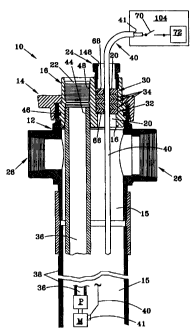
Figs. 3 and 4 illustrate an etmbodiment of a wellhead 10 according to the
present invention
for sealing with an electrical cable positioned through the wellhead, and may
include a wellhead
body 12, a retaining cap 14 and tubing hangerl6. The wellhead body 12 may
support the tubing
hanger at least partially thcrcin. A support shoulder 18 in the wcllhead body
12 may support the
tubing hanger 16. The tubing hanger 16 may includc at least two ports, a
tubing port 22 and a power
cable port 20, each eccentrically positioncd in the tubing hanger with respcct
to the other. The ESP
installation may includc a downhole electric motor M connected to a downhole
pump P which may
be connected to a lower end of a tubular 36. The EXP installation may also
include an electrical
cable 40 for supplying clcctrical power between a power source and the
electric niotor. The cable
40 may bc positioncd through the tubing hanger 16 with a pneumatic seal in the
tubing hanger
between the cable 40 and the tubing hanger 16 to pack-off or seal an interior
portion of the wellbore
i 5. All scals referred to are both pneumatic and hydraulic positive seals.
The tubing hanger 16 may include internal threads 44 within the tubing port 22
for
rcmovably securing the tubing hanger 16 to an upper end of a tubular 36
suspended of supported
within the wellbore 15. The tubing hanger 16 may include internal threads 48
in an upper portion
of the tubing port 22 for securing a surface tubular (not shown) to the tubing
hanger 16. Thereby,
fltiid pumped from the ESP may be conducted through the tubing pon 22.
fi
CA 02327987 2000-12-08
The tubing hanger 16 may include a power cable port 20 having a cable axis. A
power cable
40 may be positioned within the power cable port 20, substantially along the
cable axis. The power
cable 40 inay be an elongated, substantially flexible electric cable having
substantially unifonn outer
diniensions along its length, and having two ends, a motor end and a power
source end. The motor
cnd of the cable 40 may be removably secured to a motor on ESP, downhole in
the wellbore 15. The
power source end of the cable 40 may be removably secured to an on-off switch
70, an electrical
disconnect, a circuit breaker, a relay, electrical lugs, or an,oth.er device
for controlling the flow of
electrical power to the motor. The power source end of the cable 40 may
terminate within a control
panel box 74. An electrical power source 72 ntay be provided within the panel
74, in order to
provide electrical power to the power cable.
Thc powcr cable 40 may be of any type as known in the industry, such as
"round" cable or
"flat" cable, and may include single or multiple conductors encased in one or
more layers of
insulation, and may be flexible. The flexible power cable may be defined as
comprising an outer
sheath having substantially uniform outer dimensions, and an iiiner electrical
conductor extending
from a motor end to a power source end, the motor end electrically conneeted
to an electrical
connector on the motor, and the power source end electrically connected to an
electrical power
source.
The power cable may also include an armor sheathing 41 or protective outer
layer. The
outer surface of the armor 41 nlay include surface features such as ridges or
crevasses, which may
effect cable flexibility. Although the cable 40 may be rclatively stiff, it
will be understood by those
skillcd in the art that the power cable is none-the-less substantially
flexible, in that the cable may be
spooled or coiled.
It will be understood by those skilled in that art that in practice the power
cable 40 may
include multiple segments in order to achieve the desired length or to effect
repairs to the cable. In
this invention the power cable 40 does not necessarily terminate or include a
segment or cable
connection within or substantially adjacent the tubing hanger 16, as may be
required with prior art
embodiments such as illustt-ated in Fig. 2. Tn this invention, the power cable
40 may be a single
length segment between electrical connections 43 on the motor M and the
control panel 74 without
cable interconnections there-between.
12
CA 02327987 2000-12-08
A cable seal 34 may bc provided within the cable port 20 for pneumatically
sealing an
annulus between the OD of the power cable 40 and a seal surface 68 in the ID
of the power cable
port 20. A cable seal 34 may include packing material, packing rings, packing
eompounds or other
packing, sealing or pack-off cornponents known in the industry. The cable seal
34 may include a
tliroughborc therein to position the cable 40 through the throughbore and the
cable seal 34
substantially around an external surface of the cable 40. The seal surface 68
may be a substantially
cylindrical wall. The cable seal 34 may bc a single packing element or
multiple layers of sealing
elements. The tubing hanger 16 may also include a lower packing seat 66 for
supporting the cable
seal thereon. Upper 30 and/or lower 32 compression rings may also be included
with the cable seal
to assist compressing or encrgizing the sealing elements 34 of the cable seal.
The upper 30 and/or
lower 32 compression rings each may include a through bore for positioning or
passing the cable 40
therethrough. The lower cornpression ring 32 may be positioned between the
cable seal and the
packing seat 66.
Compression rings 30, 32, cable seals 34, a packing gland 24, and/or packing
material 34
may include circumferential cut-out portions 90 or radial splits to facilitate
ease of installation of
these components around a cable 40. The compression rings 30, 32, cable seals
34 and/or packing
materials 34 may be substantially slecvc or ring shaped, without a cutout or
split, such that each ring
shaped coniponent may require sliding thc component lengthwise over a portion
of the cable to
facilitate installation of the cable seal.
An embodiment of this invention, such as illustrated in Fig. 3, may typically
include three
packing rings 34, each of which may be about one-half inch thick, for a total
stack height of one and
one-half inches. Other embodiments may include morc or less than three rings
may be used such
that the resulting stack hcight may be more or lcss than one and one-half
inches.
A packing gland 24 selectively moveable with respect to the lower seat 66 rnay
also be
included for compressing the cable seal 34 to form a pneumatic seal bctween
the cable 40 and the
tubing port 20. The packing gland may be at least partially positioned within
a portion of the cable
port 20. The tubing hanger 16 and the packing gland 24 cach may include
threads to secure the
packing gland 24 to the tubing hanger 16, and to threadably move the packing
gland to compress the
cable seal 34, An upper portion of the packing gland 24 may include wrench
flats thereon. The
13
CA 02327987 2000-12-08
packing gland 24 may exert downward mechanical pressure on the upper
compression ring, which
may in turn compress packing rings 34 or other packing matet7ial in sealing
engagement around an
outer periphery of the ESP power cable 40. The upper compression ring 30 may
be positioned
within the power cable port 20, and may include a throughbore for positioning
the electrical power
cable therethrough. The upper compression ring 30 maybe positioned between the
cable seal 34 and
the packing gland 24 for transferring a compressive mechanical force frorn the
packing gland 24 to
the cable seal 34.
An embodinient of the invention as illustrated in Figs 3 and 4 may also
include one or more
auxiliary ports 42, such as may provide access to the interior of a wellbore
from external to the
wellbore, such as for chemical injection, capillary tubes, electrical
conductors, instrumentation,
and/or as additional tubing ports 22 for multiple-zone well eompletions_ The
tubing hanger 16 may
include female threads in each of the auxiliary ports 42 to reduce need for
additional sealing
materials within the auxiliary ports 42. An auxiliary port may typically be
between'/a inch and one
itieh, in OD. In some well coinpletions, an auxiliary port 42 may facilitate
connection of a second
or parallel tubing string to the tubing hanger, such as in a "dual-
completion." In such instance, an
auxiliary port 42 in the tubing hanger 16 may be of a larger ID, and may
include threads, such that
the tubiiig lianger may include two tubing ports 22. A first tubing port 22
may be of a different size
than the second tubing port 22 or 42. Auxiliary ports may be used for the
conduct of fluids and/or
Cle:ctricity,
Figs 5 and 6 illustrate an embodiment of the present invention wherein the
packing gland 24
includzs a substaiitially sleeve-shaped cylinder or bushing moveably
positioned at least partially
within the cable port 20. A plurality of gland retainer bolts 28 may be
included for selectively
moving the packing gland relative to the tubing hanger 16. Two or more
retainer bolts 28 may be
inoveably secured to the tubing hanger 16, and rnay be substantially
circumferentially positioned
around the cable port 20. A plurality of retainer bolt-holes 29 may be
provided in the tubing hanger
16 for adjustably securing each of a corresponding retainer bolt 28. A gland
retainer 25 may be
included for transferring a compressive force from each of the plurality of
gland retainer b4lts 28,
through the gland retainer 25 to the packing gland 24. The gland retainer may
include a plate central
plane 92 substantially perpendicular to the cable axis 94 of the cable port
20, Thereby, tightening
14
CA 02327987 2000-12-08
each of the bolts 28 may selectively compress or activate the cable seal 34 or
packing material. The
gland retainer 25 preferably may be fixedly secured to the packing gland 24,
such as by being
integrally formed, or secured such as by welding forming a single component.
The gland retainer
and the packing gland otherwise may be two distinct components. The gland
retainer and the
packing gland preferably may be fabricated from a rigid metallic material.
The upper and lower compression rings 30,32 may be manufactured from common
metals,
such as steel, brass, bronze or aluminum, or they may be manufactured from
other fibrous or
elastomeric materials such as plastics or nylon. The cable seals 34 or packing
material 34 or packing
rings 34 may be manufactured from any deformable, malleable and/or flexible
material, such as
rubber, nitryl, fiber materials, other elastomers, or soft polymers.
The reduced sizes of the cable seal 34 system of this invention may provide
several
advantages, including teduced effort and force to compress the packing. As the
outside diameter of
the packing material and the packing gland may be reduced from approximately
7.00 inches under
the prior art Fig. 1, system to approximately 2.25 inches in an embodiment of
this invention for a
similarly sized welihead body 12. In addition, this invention may require less
mechanical effort to
effectively compress the packing 34 around the cable 40, and may also create a
more reliable seal.
The packing material 34 of this invention may be less costly due to the
smaller size and due to the
fact that the packing assembly 24, 30, 32, 34 may only require a single, on-
center penetration cut or
formed in each component. This is in contrast to the prior art packing
assembly illustrated in Fig.
1, which typically requires more than one eccentric penetration be provided or
manufactured in each
component, to accommodate each of the tubing hanger projection, cable port and
auxiliary ports.
The prior art compression gland 74 and packing rings 34 may requite at least
two and often as many
as ten eccentric penetrations to be precisely located with respect to each
other, resulting in increased
complexity and misaligned installations. The wellhead components of this
invention may permit
on-center penetrations of components, without having to align multiple
penetrations in multiple
camponents. Thereby, the sealing componertts of this invention may be
manufactured with close
tolerances to effect improved sealing capabilities with each of specific ESP
cable outer jacket
dimensions.
This invention also provides a method of sealing the interior of a wellhead 10
at the upper
CA 02327987 2000-12-08
end of a wellbore 15 containing a downhole ESP P. The pump P may be powered by
a flexible
elongate electrical power cable 40 providing electrical power to the
electrical submersible pump
motor M. The power cable 40 may have uniform outer dimensions extending from a
motor end to
a power sourcc cnd. The motor end may be electrically connected to an
electrical connector on the
motor, and the power source end electrically connected to an electrical power
source 72 extemal to
the wellbore.
The method may comprise supporting a wellhead body 12 on a well casing 38 and
supporting
a tubing hanger 16 within at least a portion of the welihead body. The tubing
hanger may include
a tubing port 22 and a cable port 20 therein. The cable port 20 may contain a
lower packing seat 66.
The tubing hanger 16 may be sealingly connected with a tubular member 36 at
least partially
positioned within the wellbore 15, for passing fluid from the submersible pump
through the tubing
port 22. The power cable 40 may be positioning through the cable port 20, and
may extend from the
motor M to the power source 72 external to the wellbore, such as a control
panel 74.
A cable sea134 may be positioned at least partially within the tubing hanger
cable port to seal
between the power cable and the tubing hanger. A packing gland 24 may be
selectively moved with
respect to the tubing hanger 16 to selectively compress the cable seal 34 to
form a pneumatic seal
in the cable port 20 between the power cable 40 and the tubing hanger 16.
As illustrated in Figs. 5 and 6, a plurality of packing gland retainer bolts
28 may be
sclectively threaded to the tubing hanger 16 to selectively compress the cable
sea134 in the cable
port 20 to pneumatically seal between the power cable 40 and the tubing hanger
16. A packing gland
retainer 25 may be provided to engage each of the bolts 28 and the packin3
gland 24 to transfer
mechanical forces from the bolts 28 to the packing gland 24.
An upper compression ring 30, andlor a lower compression ring, 32, may be
provided within
the power cable port. Each compression ring 30, 32 may include a throughbore
for passing the
electrical power cable 40 therethrough. The upper ring 30 may be positioned
between the cable seal
34 and the packing gland 24 for transferring a compressive force from the
packing gland to the cable
seal.
The methods for sealing the intcrior of a wellbore 15 aceording to this
invention may effect
a pneumatic seal, which provides a working or opcrating differential pressure
of at least 500 psig.
16
CA 02327987 2000-12-08
More particularly, thc mcthods of this invcntion may effect a pneumatic seal
that is operable at a
differential pressurc of at least 750 psig.
Alternativc cmbodiments for the cable seal of this invention may include a
cable seat 34
which consists of only one packing ring. The packing ring may range in height
from approximately
three-fourths of an inch thick to in excess of four inches thick. Embodiments
of this invention may
provide particular surface shapes on adjacent surfaces of the compression
rings andlor the packing
rings, as opposed to providing flat adjacent surfaces as illustrated in Fig.
3. For example, each
packing ring 34 may include a chevron type shape on one or both sides of the
rings and/or packing.
Cable seal components altern,atively may be formed into two substantially
equal halves, or
each component may be a substantially single component including a split,
cutout or
circumferentially removed section to allow lateral positioning of the
component around the power
cable, thereby avoiding snaking the cable through the penetrations in the
components. Similarly,
as illustrated in Fig. 4, a packing gland may include a circumferential cutout
section 90 removed to
allow the packing gland to be laterally installed around the power cable
without snaking the gland
over the length of the cable.
Other embodiments of a wellhead according to this invention may provide an
auxiliary port
142 through the cable packing 34, compression rings 30, 32, and packing gland
24. The auxiliary
port 142 may be a separate through passageway from the cable through
passageway in the sealing
members, 24, 30, 32, 34. For example, such port 142 may be '/." port for
positioning an instrument,
tube, or clcctrical conductor therethrough, to provide fluid eommunication
and/or electrical
conununication betwccn an interior of the wellbore and an external to the
wellbore, through the
auxiliary port. Such embodiment may also reduce the number of or eliminate
auxiliary ports within
the body of the tubing hanger 16.
Alternative embodiments of the present invention may provide an additional set
of internal
or extemal threads 148, or clamp profile on an end of the packing gland
opposite the end of the
packing gland engaging the cable scal 34. Such threads may provide for
removably securing
electrical conduit to the packing gland to protect the cable between the power
source and the tubing
hanger. A tubing hanger may also provide a conduit connector, 140 having a
conduit connector axis
17
CA 02327987 2000-12-08
141 positioned along the cable port axis 94, such as a sleeve shaped nipple
fixedly secured thereto,
or to a packing gland retainer 25, as illustrated in Fig. 6, to connect
electrical conduit to the tubing
hanger 16 and/or the retainer 25.
An alternative embodiment of this invention may include a tubing hanger
providing a slip
bowl with a portion of the tubing port. A plurality of slip segments may be
included and positioned
within the tubing port, belween a tubular member positioned in t]uough the
tubing port and the slip
bowl portion of the tubing port. Thereby, the slip segments may grip the
tubular member to support
the tubular at least partially within and partially without of the wcllbore.
In such embodiment, the
cable port may be included in the tubing hanger, substantially adjacent aiid
parallel the tubing port.
Otlier alternative embodiments of a wellhead according to the present
invention may
eliminate the retainer cap 14. The tubing hanger 16 niay be retained in place
by the weight of the
tubing string 36 suspended therefrom. In other embodiments, the wellhead body
may include bolt
holes or clanip profiles, such that tubing hanger retainers niay be secured to
the wellhead body, such
as by boltiiig or clamping thereoti, and extend to engage a portion orthe
tubing hanger to secure the
tubing hanger within tha; wellhead body.
18