Note: Descriptions are shown in the official language in which they were submitted.
CA 02328158 2000-10-10
1
DISPOSABLE FLUID OR PARTICULATE APPLICATOR
PCT/AU99/00307
Received 03 December 1999
The present invention relates to a disposable and sterile fluid or particulate
applicator. It has particular application in the medical and food technologies
where the supply of a fluid or particulate under sterile conditions is
paramount.
BACKGROUND OF THE INVENTION
Single use containers have been known to be used to provide a sterile fluid or
particulate. For example, such containers may provide a saline solution to
wash wounds, may contain sauces to be added during cooking or may house
materials that can not be exposed to air.
1 0 Similarly, multi-use containers such as sauce bottles are also known where
they may be used many times and even be refillable. Generally multi-use
containers also include a tool to assist in dispensing of the fluid or
particulate.
These tools, such as nozzles, can become contaminated through continued
usage. Remnants of the fluid or particulate can remain in the nozzle and can
over time start to degrade. Furthermore, the nozzle can become blocked if it
is
in physical contact with a food during use, such as the application of sauce
internally to a pie. Not only is the blockage inconvenient, but it can pose a
health risk.
It is an object of the present invention to provide a disposable or one-use
only
2 0 fluid or particulate dispenser that overcomes at least some of the
abovementioned problems or provides the public with a useful alternative.
SUMMARY OF THE INVENTION
Therefore in one form of the invention there is proposed a fluid or
particulate
dispenser including:
2 5 a sachet having a reservoir and a cover;
said reservoir having an internal volume adapted to contain a fluid or
particulates and including a spout extending to a distal tip having an
aperture
for dispensing said fluid or particulates;
said cover having an internal volume adapted to enclose and externally
3 0 protect the outer surface of the spout and including a sealing means to
seal
~;P4~.i~l~E~ SHEET
~~i'~~~~~
CA 02328158 2000-10-10
2
PCT/AU99/00307
Received 03 December 1999
said aperture to prevent said fluid or particles from contacting said outer
surface, removable from said reservoir to enable for the dispensing of said
fluid or particulates from said reservoir through said spout.
Preferably said cover is frangibly attached to said reservoir. This allows the
cover to be easily torn from the reservoir. It is also to be understood that
the
term frangible is not intended to limit it to the construction that the cover
is
attached to the reservoir during manufacture. For example, an existing sachet
may be modified to provide for a reservoir and a cover member by the
application of a heat seal that assists in providing the frangible attachment.
1 0 Preferably said sachet is made from a flexible material. This assist in
allowing
the fluid to be pressurised and expelled from said reservoir.
Preferably said cover includes a sealing means to seal said aperture. IN this
way, the fluid does not seep into the cover. One way of doing this is for the
sealing means to be a plug.
Preferably the spout is sealingly attached to said reservoir member. For
example, the spout could be glued to the inside of the reservoir member.
In a further form of the invention there is proposed a fluid or particulate
dispenser including:
a fluid sachet including a flexible reservoir and a cover frangibly attached
to
2 0 said reservoir;
said reservoir having an internal volume adapted to support a fluid and
including a neck portion extending to a distal tip having an aperture for
dispensing said fluid, said neck portion being slidable between a first
position
located within said internal volume and a second position extending from said
2 5 internal volume;
whereby in use, the said cover frangible seal is fractured and removed from
said reservoir and whereby applying an external force on said reservoir fluid
pressure causes the neck portion to slide to said second position and fluid to
flow through said aperture.
3 0 In a still further form of the invention there is proposed a fluid or
particulate
dispenser including;
a sachet having a flexible reservoir and a cover frangibly attached to said
~ai~l~i~lr?~!." 31'~E
~WF:~(e~.6~ .
CA 02328158 2000-10-10
3
reservoir;
PCT/AU99/00307
Received 03 December 1999
said reservoir having an internal volume adapted to support a fluid and
including a neck extending to a distal tip having an aperture for dispensing
said fluid, said neck being foldable;
said cover having an internal volume adapted to enclose and externally
protect the outer surface of the spout and including a sealing means to seal
said aperture to prevent said fluid or particles fram contacting said outer
surface, removable from said reservoir to enable for the dispensing of said
fluid or particulates from said reservoir through said spout
1 0 whereby in use, the said cover frangible seal is fractured and removed
from
said reservoir and whereby applying an external force an said reservoir fluid
causes said neck potion to fold out and fluid flows through said aperture.
Preferably the cover is frangibly attached to said reservoir along a seam. The
seam could be made by appropriate heat welding that also may assist in
sealing the spout to the reservoir.
Preferably said neck portion is resilient to maintain its structural integrity
when
inserted into an area where the fluid or particulate is to be applied. For
example it has been found highly useful by the inventors to use the invention
to apply sauce to a bottle as well as insertion of appropriate medical fluids
into
2 0 the rectum.
For example the dispenser could be used for the dispensing of sauce into pies
or pasties.
In preference said dispenser further includes an inner bladder disposed with
said internal volume, said neck portion fluidly connected to said inner
bladder.
2 5 In a still further form of the invention there is proposed a fluid of
particulate
dispenser including:
a sachet defining an internal volume and including a neck portion that is to
be
contained within the internal volume of said sachet and adapted to divide the
sachet into a reservoir and a cover;
3 0 said neck portion including an aperture for dispensing said fluid and/or
particulate, said sachet further including an inner surface configured to seal
said aperture to isolate said neck from said fluid and/or particulate.
~M~'1~1~~1=~' ~H~~'
9F>~~i~a~ k
CA 02328158 2000-10-10
4
PCT/AU99/00307
Received 03 December 1999
Preferably the dispenser further includes a tool enclosed by said cover. The
tool could additionally provide for a seal against the aperture.
Therefore, one can see that the present invention provides for a fluid or
particulate dispenser that is designed to be disposed off after use. This
minimises the risk to public health. It can also be used in medical
applications
where the provision of sterile fluids or particulates as well as the provision
of
small tools. The dispenser may also include fluid or particulate spouts or
necks that assist in controlling the direction of the fluid flow. Being made
from
a flexible material the dispenser is relatively inexpensive and can be
1 0 effectively stored adding yet a further advantage. However it is to be
understood that the dispenser can be made to be partially flexible and
partially rigid. For example, the base of the dispenser may be rigid to afford
additional protection against storage and dispensing.
DESCRIPTION OF THE PREFERRED EMBODIMENTS
Several embodiments of the invention are described hereunder in some detail
with reference to and as illustrated in the accompanying drawings, in which:
Fig 1 is a plan view of a fluid dispenser according to a first
embodiment of the invention;
Fig 2 is a side cross-sectional view of the dispenser of Figure 1;
2 0 Fig 3 is a front cross-sectional view of the dispenser of Figure 1;
Fig 4 is a perspective view of a fluid dispenser according to a second
embodiment of the invention;
Fig 5 is an exploded view of the fluid dispenser of Figure 4 showing
the fluid dispenser in use;
2 5 Fig 6 is a side cross-sectional view of the fluid dispenser of Figure 4;
Fig 7 is a perspective view of a fluid dispenser according to a third
embodiment of the invention;
~M~i~~i:~ri ~H~~"r
n ~-,.,.L. l, y o j
CA 02328158 2000-10-10
PCT/AU99/00307
Received 03 December 1999
Fig 8 is a perspective view of the fluid dispenser of Figure 7 showing
the dispenser being prepared for use;
Fig 9 is a perspective view of a fluid dispenser according to a fourth
embodiment of the invention;
5 Fig 10 is a perspective view of the fluid dispenser of Figure 9
showing the dispenser being prepared for use;
Fig 11 is a side cross-sectional view of the dispenser of Figure 9;
Fig 12 is a plan view of a dispense according to a fifth embodiment
of the invention;
Fig 13 is a cross-sectional view of the dispense of Figure 12;
Fig 14 (a) and (b) are plan and cross-sectional view of a dispense
according to a sixth embodiment of the invention;
Fig 15 (a) and (b) are plane and cross-sectional views of the
dispenser of Figure 14 prepared for use;
Fig 16 is a perspective partially cutaway view of a fluid dispenser
according to a seventh embodiment of the invention; and
Fig 17 is an exploded perspective view of the fluid dispenser of
Figure 16 prepared for use.
DESCRIPTION OF THE PREFERRED EMBODIMENTS
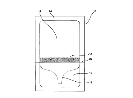
2 0 Referring now to the drawings in detail it is to be understood that like
numerals
refer to like elements. Thus there is shown in Figures 1-3 a fluid dispenser
10
according to a first embodiment of the invention that may be used to dispense
liquids such as tomato sauce. The dispenser 10 includes a tool 12 that divides
the dispenser into a reservoir 14 and a cover 16. The tool, in this embodiment
2 5 being a spout, is sealingly circumferentially attached to the inside of
the
dispenser around internal radius 18 to prevent any fluid in the reservoir
flowing into the cover except through an aperture in the spout. To allow
~ft4E~ ~~~~~1~ BHEE~'
8~'~ ~;I~.~,~
CA 02328158 2000-10-10
6
PCT/AU99/00307
Received 03 December 1999
access to the spout, the cover simply needs to be removed from the reservoir
at a location forward from said radius. This can be done by the use of an
external cutting tool, such as a pair of scissors. To however assist in this
regard a seam 20 may be introduced forward of the radius, such as that made
by a heat seal, which allows the cover to be physically torn from the
reservoir
thereby exposing the spout.
To manufacture the dispenser one therefore simply needs a single sachet
into which is introduced and fixedly attached spout 12, and whereby a heat
seal 20 is then applied forward the location where the spout 12 is fixed to
the
1 0 dispenser 10 to enable the cover 16 to be frangibly attached to the
reservoir
14 . To ensure that no fluid flows from the reservoir into the cover, the
aperture
22 of the spout may be appropriately sealed, although a particular seal is not
shown. The cover may also assist in the sealing but that is discussed in a
further embodiment.
1 5 Alternatively two sheets of suitable material, such as plastic, may be
positioned one over a spout and one under a spout and whose edges 24 are
then heat sealed to thereby define the dispenser.
To dispense fluid, such as sauce, the cover 16 is torn along the frangible
seam 20 to thereby expose spout 12 and aperture 22. By pressurising the
2 0 reservoir 14 by simply squeezing it externally 14, fluid is caused to flow
out
through said aperture 22.
The spout 12 may be manufactured so as to be more resilient than the rest of
the dispenser 10 and thus can be adapted to be inserted into food, such as
pies and pasties, so that sauce can be dispensed directly into the pies or
2 5 pasties. Once the sauce has been dispensed, the dispenser is disposed of
eliminating problems of public health. Since the spout is completely covered
by the cover prior to its use it is kept in a sterile environment.
Referring now to figures 4-6 there is shown a second embodiment of the
invention where a spout 12 is manufactured integrally with the reservoir 14.
In
3 0 this embodiment, the cover 16 is removably attached to the reservoir 14,
with
the seam 20 once again being one allowing the cover to be torn from the
reservoir. In this embodiment the cover also includes a cavity 26
correspondingly shaped to the spout and including an end 28 that is adapted
~M~f~I~~C~ ~HE~'
I~~~ IBC 1
CA 02328158 2000-10-10
7
PCT/AU99/00307
Received 03 December 1999
to sealingly engage the aperture 22 to prevent fluid 28 flowing into the cover
member when it is attached to the reservoir. In this embodiment it may be
useful to use a material that is more resilient and to provide a support for
the
spout so as maintain integrity in its shape.
Referring now to figures 7 and 8 there is shown a third embodiment of the
invention. Spout 12 is slidably disposed within the reservoir. Located towards
the spout end of the reservoir is a join or seam 20 dividing the dispenser
into a
reservoir 14 and cover 16. The edge 30 of the reservoir includes an opening
32 positioned to be co-axial with the spout 12. When the cover 16 is removed
from the reservoir 14, the opening 32 is exposed. The spout can then slide
through the opening. Obviously the edges of the spout remain in sealing
engagement with the reservoir to ensure that any fluid within the reservoir
can
only flow through the spout. To use the dispenser one simply tears the cover
exposing the opening and then applies pressure to the reservoir behind the
spout which pressurises the reservoir causing the spout to move through the
opening until its size is equal to that of the opening at which point the
fluid is
pressurised to flow out through the spout. The spout may also be
manufactured from a hard material enabling more control over the insertion of
the nozzle into food by being manufactured of a resilient material.
2 0 A fourth embodiment of the present invention is shown in Figures 9-11. The
dispenser 10 includes a bladder 34, one end of the bladder 34 being foldable
along folds 36 and including a spout 12. The bladder is enclosed by the
reservoir 14 and cover 16 that are integrally attached to each other and
define
the outside of the dispenser. The cover 16 is tearingly removable to expose
2 5 the side of the reservoir and through which can then extend the spout 12.
By
applying pressure, the reservoir containing the fluid is pressurised acting on
the spout that is then moved outwardly until the folds are straightened. Once
again, the nozzle may be manufactured of resilient material allowing the spout
to be inserted into foods such as pies. Although the construction of Figures 9-
3 0 11 shows a bladder, it is to be understood that instead of a bladder, the
foldable portion 36 may simply be attached to the inside walls of the
reservoir
14 without extending throughout the whole bladder. The exact configuration
would of course depend upon what strength the bladder needs to be
manufactured to and the cost and ease of manufacture.
3 5 A fifth embodiment of the invention can be seen in Figures 12 and 13 where
~M~Pdi:.y~h ~H~F~
w~=~~I~G~~
CA 02328158 2000-10-10
8
PCT/AU99/00307
Received 03 December 1999
the spout is an integral part of the reservoir. The cover is tearingly or
frangibly
attached along seam 20 to the spout portion of the reservoir. This embodiment
may be useful in situations where the spout need not be inserted into matter
but where it is imperative that the outside of the aperture is kept sterile.
In
addition the aperture 22 is sealed by plug 38 that is not attached to the
cover.
To break the seal instead of removing the cover and then the plug., the plug
may be twisted by, for example, applying rotational motion 40 to the plug
through the cover thus breaking the seal on the aperture. Only then is the
cover 16 removed thereby removing the plug 38 and exposing the spout 12.
Shown in figures 14 and 15 is a sixth embodiment of the invention where the
cover is frangibly attached to the reservoir and where the cover 16 is
correspondingly shaped to the spout 12. Somewhat similar to the previous
embodiment in including a plug that can be broken by applying rotational
motion to it, in this embodiment the cover completely extends over the spout
1 5 protecting it from the outside.
Yet a further embodiment of the invention can be seen in Figure 16 and 17
whereby besides the cover protecting a spout for the dispensation of fluid or
particulates, the cover may also accommodate taols that may assist in a
particular application. Shown in this embodiment are tweezers 42 including a
2 0 base 44 adapted to seal aperture 22. The cover 16 is of a larger
construction
so as to accommodate the tweezers 42 which are kept in a sterile
environment. This embodiment may have particular application for the
medical field where tools such as tweezers that may be used to treat wounds
need to be kept in a sterile environment. At the same time the reservoir may
2 5 include a saline solution that may be used to wash the wound. In this way,
the
dispenser not only provides the sterile saline solution but also tweezers that
may assist in cleaning the wound. Both are kept in the one dispenser and are
thus not only convenient but are used only once minimising risk of infection.
Other variations to the invention that are not shown include spouts with
3 0 multiple nozzles, or covers that include different tools. It is also to be
understood wherein reference has been made to the dispensing of fluid, it is
to be understood that the dispenser may equally well be used to dispense
particulates such as powders or creams.
The foregoing describes only several embodiments of the present invention
~NEEN~J~=~ BHE~'
a~~~a~:'~~
CA 02328158 2000-10-10
PCT/AU99/00307
Received 03 December 1999
and modifications, obvious to those skilled in the art, can be made thereto
without departing from the scope of the present invention.
~~i~C?~~~ ~Hir~ p '
p~w~l~e~~