Language selection

Search

Patent 2328241 Summary

Third-party information liability

Some of the information on this Web page has been provided by external sources. The Government of Canada is not responsible for the accuracy, reliability or currency of the information supplied by external sources. Users wishing to rely upon this information should consult directly with the source of the information. Content provided by external sources is not subject to official languages, privacy and accessibility requirements.

Claims and Abstract availability

Any discrepancies in the text and image of the Claims and Abstract are due to differing posting times. Text of the Claims and Abstract are posted:

  • At the time the application is open to public inspection;
  • At the time of issue of the patent (grant).
(12) Patent: (11) CA 2328241
(54) English Title: DISCHARGE OUTLET CONTROL
(54) French Title: SYSTEME SERVANT A REGULER UNE SORTIE D'EVACUATION
Status: Deemed expired
Bibliographic Data
(51) International Patent Classification (IPC):
  • B65G 11/20 (2006.01)
  • B65D 90/54 (2006.01)
  • B65D 90/56 (2006.01)
  • B65G 47/04 (2006.01)
  • B65G 47/19 (2006.01)
  • B65G 69/16 (2006.01)
(72) Inventors :
  • HUMPHRYSON, IAN GEORGE (Australia)
(73) Owners :
  • HUMPHRYSON, IAN GEORGE (Australia)
(71) Applicants :
  • HUMPHRYSON, IAN GEORGE (Australia)
(74) Agent: RICHES, MCKENZIE & HERBERT LLP
(74) Associate agent:
(45) Issued: 2008-01-08
(86) PCT Filing Date: 1999-03-18
(87) Open to Public Inspection: 1999-10-21
Examination requested: 2003-11-14
Availability of licence: N/A
(25) Language of filing: English

Patent Cooperation Treaty (PCT): Yes
(86) PCT Filing Number: PCT/AU1999/000187
(87) International Publication Number: WO1999/052797
(85) National Entry: 2000-10-13

(30) Application Priority Data:
Application No. Country/Territory Date
PP 2969 Australia 1998-04-15

Abstracts

English Abstract


A discharge flow control means comprising a plurality of flexible
elongate elements (19) adapted to be supported at one end from a discharge
outlet (23) to extend from the outlet (23) in the direction of the discharge
and
across the flow path from the discharge outlet (23).


French Abstract

Moyens servant à réguler un écoulement d'évacuation et comprenant une pluralité d'éléments souples allongés (19) conçus pour être supportés à une extrémité par une sortie d'évacuation (23), de manière à s'étendre depuis la sortie (23) dans le sens de l'évacuation et à travers le trajet d'écoulement depuis ladite sortie (23).

Claims

Note: Claims are shown in the official language in which they were submitted.


-7-


What is claimed is


1. A discharge flow control means comprising a plurality of flexible elongate
elements adapted to be supported at one end from a discharge outlet to extend
from the outlet in the direction of the discharge and across the flow path at
its
position spaced outwardly from the discharge outlet whereby the discharge flow

control means has an insignificant affect on the rate of discharge from the
outlet.

2. A discharge flow control means as claimed at claim 1 wherein the elongate
elements are adapted to be located around the perimeter of the discharge
outlet.

3. A discharge flow control means as claimed at claim 1 or 2 wherein the
elongate elements surround the discharge outlet.


4. A discharge flow control means as claimed at any one of claims 1 to 3
wherein the elongate elements are resiliently flexible.


5. A discharge flow control means as claimed at any one of claims 1 to 4
wherein the elongate elements are formed of an elastomeric material.


6. A discharge flow control means as claimed at any one of claim 1 to 5
wherein
the elongate elements are formed with openings along their length.


7. A discharge flow control means as claimed at any one of claims 1 to 6
comprising a substantially square or rectangular panel of sheet material
formed with
a plurality of transversely spaced slits extending from one end and
terminating short
of the other end and which define said elongate elements therebetween, said
other
end of said length of sheet material having a confirguration to be applied to
the
discharge outlet.


-8-


8. A discharge flow control means as claimed at any one of claims 1 to 7
wherein the elongate elements are supported at each end to substantially
opposed
sides of the discharge outlet whereby the central portion of the elongate
elements
lie across the flow path from the discharge outlet.


9. A discharge flow control means as claimed at claim 1 wherein the elongate
elements comprise at least two sets of elongate elements supported at each end
to
substantially opposed sides of the discharge outlet and wherein the ends of
the sets
of elongate elements are angularly offset from each other around the discharge

outlet and the central portions of the sets overlap.


10. A discharge flow control means as claimed at claim 9 wherein the discharge

control means comprises at least two substantially square or rectangular
panels of
sheet material formed with a plurality of transversely spaced slits each
terminating
short of each end of the sheet material and which define the sets of elongate
elements therebetween, the ends of the lengths of sheet material having a
configuration to be applied to the discharge outlet in opposed relation to
each other

Description

Note: Descriptions are shown in the official language in which they were submitted.


CA 02328241 2000-10-13

WO 99/52797 PCT/AU99/00187
-1-
Titfe: Discharge Outte# Control

Field of the invention

The present invention relates to a dispersal means which can be utilised with
discharge outlets.

A particular apptication of the invention relates to modification of discharge
outlets which are utilised in carrying fluid materials during mineral
processing
where the fluid material (which may be particulate materials., slurries or
liquids)
are delivered from an outlet into a hopper chute or the like. A further
application
relates to circumstances vvhefe a fluid is delivered into a body of liquid

Background

It has been found that the delivery of a fluid material from the discharge
outlet
can result in significant wear on the components on which the fluid material
is
incident and in the case of abrasive fluid materials the wear can be quite
significant and can result in the pnenature destruction of the components
utilised in the conveying of the fluids.

In addition where a fluid material is delivered from an outlet into a body of
liquid
the discharge often results in air being carried into the liquid as the fluid
material
enters. the liquid and this can be particularly evident as the velocity of the
discharge into the liquid 'micreases. The entry of air into the body of liquid
can
create difficulties wherethe-body of liquid is associated with a pump or where
it
is desired that there be some settting of the fluid material being delivered
into
the liquid.

It is an object of this inventTorrto provide a means which is able disperse
and or
reduce the velocity of the fluid flow from discharge outlets without
significantly
adversely affecting the discharge rate from the outlet.


CA 02328241 2000-10-13

WO 99/52797 PCT/AU99/00187
-2-
Disclosure of the hrverttion

Accordingly the invention resides in a discharge flow control means comprising
a plurality of flexible elongate e#err-errts adapted to be supported at one
end from
a discharge outlet to extend from the outlet in the direction of the discharge
and
across the flow path from the discharge outlet.

According to a preferrect feature of the invention, the elongate elements are
adapted to be located around the perimeter of discharge outlet. According to
one embodiment the efortgate-e4ements surround the discharge outlet.

According to a prefened feature of the invention elongate elements are
resiliently flexible. According to one errrbodirnent the elongate elements are
formed of an elastomeric or etastomeric-like material.

According to a further prefEg , ed feature of the invention the elongate
eiements
are formed with opemngs atong their length.

According to a further pre#erred feature the discharge control means comprises
a substantially square or rectangular panel of sheet material formed with a
plurality of transversally spaced slits extending from one end and terminating
short of the other end and which define said efongate elements therebetween,
said other end of said length of sheet material being adapted to be applied to
the discharge outlet.

According to an attemative pre#erred form the elorTgate elements are supported
at each end to substantialty opposed sides of the discharge outlet whereby the
central portion of the etongate elerrrents lie across the flow path from the
discharge outlet. According to an embodiment of the invention the discharge
control means comprises a_substantially square or rectangular panel formed
with
a plurality of transversally spaced slits each terminating short of each end
of the
sheet material and which defrne said etorrgate elm, K,-, its ti iet ebetween,
the ends


CA 02328241 2007-02-12

-3-
of said length of sheet material being adapted to be applied to the discharge
outlet
in opposed relation to each other.

According to an alternative preferred form the elongate elements comprise at
least
two sets of elongate elements wherein each set of elongate elements are
supported
at each end to substantially opposed sides of the discharge outlet whereby the
central portion of each set of elongate elements lie across the flow path from
the
discharge outlet and wherein the ends of the sets of elongate elements are
angularly offset from each other around the discharge outlet and the central
portions
of the sets overlap.

In one aspect, the present invention resides in a discharge flow control means
comprising a plurality of flexible elongate elements adapted to be supported
at one
end from a discharge outlet to extend from the outlet in the direction of the
discharge and across the flow path at its position spaced outwardly from the
discharge outlet whereby the discharge flow control means has an insignificant
affect on the rate of discharge from the outlet.

The invention will be more fully understood in the light of the following
description of
several specific embodiments.

Brief Description of the Drawings

The description is made with reference to the accompanying drawings of which:
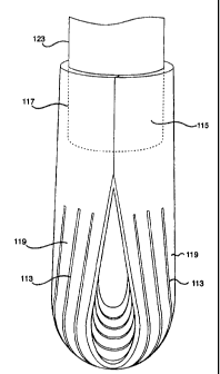
Figure 1 is a side elevation of the first embodiment;

Figure 2 is a plan view of the first embodiment prior to application around a
chute;
Figure 3 is a schematic view of the first embodiment in use;


CA 02328241 2007-02-12

- 3a -
Figure 4 is a schematic isometric view of a discharge outlet accommodating the
second embodiment;

Figure 5 is a plan view of the second embodiment prior to application around a
discharge outlet;

Figure 6 is an upper isometric view of the third embodiment of the invention;
and


CA 02328241 2000-10-13

WO 99/52797 PCT/AU99/00187
-4-
Figure 7 is an undemeath isometric view of the third embodiment of the
invention.

Description of Severat of the invention

The first embodiment is directed to a discharge corrtrol means for utilisation
with
a discharge outlet. The first embodimerit r.omprises a sheet of an elastomeric-

like material which may be formed from artificial or naturai rubber,
polyurethane
a iike efastomeric materiai which has a generally square or rectangular shape
and which is formed with a plurality of slits 13 extending from one end 15 and
terminating short of the other end 17 and which serve to form a plurality of
elongate elements 19. A number of openings 21 are provided along the length
of each of the elongate-eternents 19. The other end 17 is adapted to be
applied
around a chute to form a sutrstantially cylindrical member as shown at Figures
1
and 3 whereby the elongate e#emerrts 19 extenctfrom the chute 23.

The first embodiment has particular application for use with chutes which have
a
discharge which is inclined to the horizontal axis. Because of their flexible
nature the elongate ekments have a natural tendency to depend downwardly
from the outer end of the chute 23 and thus to lie across the outlet. This
tendency brings the elongate e4ements 19 into contact with the fluid flow
being
discharged from the outlet 23 which results in the fluid flow being dispersed.
As
a result the elongate elements serve to reduce the impact velocity of the
fluid
flow onto the elements with which the flow makes caontact and the distribute
the
fluid flowing from the discharge outlet over a wider area than would otherwise
be
the case, without signrficantty inhibitingthe fluid flow from the outlet.

The second embodiment as shown at Figures 4 and 5 is formed from a panel
111 of sheet material which again may be forrned of artificial or natural
rubber or
polyurethane or a like elastorrterTC material. The panel 211 is of a generally
rectangular shape and is formed with a plurality of transversally spaced slits
113
each of which terrrrinate short of each end 115 and 117 to define the elongate


CA 02328241 2000-10-13

WO 99/52797 PCT/AU99/00187
-5-
elements 119 therebetween. The ends 115 and 117 of the panel 111 are
adapted to be applied around the chute 123 in opposed relation such that the
intermediate portion of each of the elongate elements 119 lie across the flow
path from and discharge chute 123.

The second embodiment has particuiar application to outlets which are of a
generally vertical orientation whereby the fluid flow from the discharge
outlet is
directed generally downwardly. The presence of the elongate elements below
the discharge outlet 123 serves to disperse the discharge without
significantly
impeding the flow from the discharge and developing any back pressure on the
discharge outlet. As a resutt the velocity with which the fluid
flow impacts with the corrtponents onto which the fluid flow is directed is
significantly reduced and the area of impact is greatly increased which
results in
a significant reduction in the degree of wear on such components.

The third embodiment as shown at Figures 6 and 7 is generally of a similar
form
to that of the second embodimerrt in that it comprises two panels 211 which
are
each of a generally rectangLiar.shape.and each panel is formed with a
plurality
of transversally spaced slits 213 each of which terminate short of each end
215
and 217 and which define the elongate etements 219 therebetween. The ends
115 and 117 of each of the panels 211 i d in a side by side
relationship to define a tubular portion 225 whereby the ends 215 and 217 of
each panel are in opposed relation to each other and the intermediate portion
of
each panel which comprises the central portion of the elongate-etements 219
lie
across the tubular portion 225 in an overlapping relationship as shown. The
tubular portion is adapted to be able to be applied around a discharge chute
(not
shown) such that the centrai portion of the etongate elements 219 lie in an
overlapping retationshiF acrass the fluid itow path from discharge chute 223.

It has been found that the third embodiment has application in use with
discharge outlets which are detivering fluid into a body of liquid. As a
result of
the use of the emtrodimerit the vetocity of the fluent materiat, on entry into
the


CA 02328241 2000-10-13

WO 99/52797 PCT/AU99/00187
-6-
liquid, is significantly reduced and consequently the amount of air which is
carried into the liquid is reduced. As a result the operating characteristics
of any
pumps associated with the liquid are not adversely influenced by the presence
of air in the liquid being pumped.

Throughout the specification, unless the context requires otherwise, the word
"comprise" or variations such as "comprises" or "comprising", will be
understood
to imply the inclusion of a stated integer or group of integers but not the
exclusion of any other integer or group of integers.

It should be appreciated that the scope of the present invention need not be
limited to the particular scope of the embodiments described above.

Representative Drawing
A single figure which represents the drawing illustrating the invention.
Administrative Status

For a clearer understanding of the status of the application/patent presented on this page, the site Disclaimer , as well as the definitions for Patent , Administrative Status , Maintenance Fee  and Payment History  should be consulted.

Administrative Status

Title Date
Forecasted Issue Date 2008-01-08
(86) PCT Filing Date 1999-03-18
(87) PCT Publication Date 1999-10-21
(85) National Entry 2000-10-13
Examination Requested 2003-11-14
(45) Issued 2008-01-08
Deemed Expired 2009-03-18

Abandonment History

There is no abandonment history.

Payment History

Fee Type Anniversary Year Due Date Amount Paid Paid Date
Application Fee $150.00 2000-10-13
Maintenance Fee - Application - New Act 2 2001-03-19 $50.00 2000-10-13
Maintenance Fee - Application - New Act 3 2002-03-18 $50.00 2002-02-27
Maintenance Fee - Application - New Act 4 2003-03-18 $50.00 2002-12-24
Request for Examination $400.00 2003-11-14
Maintenance Fee - Application - New Act 5 2004-03-18 $100.00 2004-01-15
Maintenance Fee - Application - New Act 6 2005-03-18 $100.00 2005-01-10
Maintenance Fee - Application - New Act 7 2006-03-20 $100.00 2006-01-12
Maintenance Fee - Application - New Act 8 2007-03-19 $100.00 2007-01-29
Final Fee $300.00 2007-10-26
Owners on Record

Note: Records showing the ownership history in alphabetical order.

Current Owners on Record
HUMPHRYSON, IAN GEORGE
Past Owners on Record
None
Past Owners that do not appear in the "Owners on Record" listing will appear in other documentation within the application.
Documents

To view selected files, please enter reCAPTCHA code :


To view images, click a link in the Document Description column. To download the documents, select one or more checkboxes in the first column and then click the "Download Selected in PDF format (Zip Archive)" or the "Download Selected as Single PDF" button.

List of published and non-published patent-specific documents on the CPD .

If you have any difficulty accessing content, you can call the Client Service Centre at 1-866-997-1936 or send them an e-mail at CIPO Client Service Centre.


Document
Description 
Date
(yyyy-mm-dd) 
Number of pages   Size of Image (KB) 
Description 2000-10-13 6 261
Representative Drawing 2001-02-06 1 8
Representative Drawing 2007-12-04 1 7
Abstract 2000-10-13 1 44
Cover Page 2007-12-04 1 35
Cover Page 2001-02-06 1 33
Claims 2000-10-13 2 77
Drawings 2000-10-13 7 104
Description 2007-02-12 7 268
Claims 2007-02-12 2 64
Fees 2004-01-15 1 41
Fees 2002-02-27 1 48
Assignment 2000-10-13 4 121
PCT 2000-10-13 9 378
Fees 2002-12-24 1 37
Prosecution-Amendment 2003-11-14 1 38
Fees 2006-01-12 1 36
Prosecution-Amendment 2004-01-20 2 34
Fees 2005-01-10 1 37
Prosecution-Amendment 2006-09-22 2 72
Fees 2007-01-29 1 46
Prosecution-Amendment 2007-02-12 13 486
Correspondence 2007-10-16 1 48
Correspondence 2007-10-26 1 55