Note: Descriptions are shown in the official language in which they were submitted.
CA 02328384 2000-10-11
WO 99/54151 PCT/US99/08610
APPLICATOR FOR CORRECTION FLUID
The invention relates to applicators for correction fluids.
Correction fluids are used for correcting handwritten, typewritten or
photocopied markings on paper. Generally, correction fluids are applied to a
paper
surface in liquid form. After application, the fluids harden to a film which
can
effectively cover erroneous markings on the surface and can receive a
corrected
marking. Correction fluids typically contain a resin that provides the
flexible film,
and an opacifying pigment, usually titanium dioxide, dispersed in a liquid.
The
liquid may be water or an organic solvent.
Correction fluids are often supplied in a small container with an
applicator brush attached to the cap through a stem. A user unscrews the cap
from
the container and withdraws the brush loaded with correction fluid. The user
then
contacts the erroneous marking with the brush, and correction fluid is
transferred to
the substrate to cover the marking.
The invention relates to an applicator that can be used to apply
correction fluid. The applicator preferably includes a stem, an applicator tip
including foam, and preferably a flexible material, i.e., a flexor, within the
tip. The
applicator is easy to use and preferably can be inserted into a correction
fluid
container in the same general manner as brush applicators. The applicator
provides
an even laydown of correction fluid on a substrate, resulting in good
correction
quality. The applicator has good durability and facilitates precise
correction.
In one aspect, the invention relates to an applicator, including a stem
and an applicator tip including foam, having a flexibility of at least 0.0005
inch of
deflection per gram of force, preferably at least 0.002 inch of deflection per
gram of
force.
In another aspect, the invention features an applicator, including a
stem and an applicator tip including foam, having an angled chisel-shaped
application surface for applying correction fluid to a substrate.
In another aspect, the invention relates to an applicator including a
stem and an applicator tip including a quenched foam. By quenched foam, it is
meant a foam that is reticulated (substantially all membranes have been
removed to
make it open-celled) by chemical methods.
CA 02328384 2000-10-11
WO 99/54151 PCT/US99/08610
-2-
In another aspect, the invention relates to an applicator including a
stem and an applicator tip including foam having an average pore size of
between
20 ppi (pores per linear inch) and 130 ppi.
The invention further relates to correction fluid products including a
body defining a reservoir and having an opening. The reservoir includes a
correction fluid, and the applicator is inserted through the opening so that
the
portion is in contact with the correction fluid. Preferably, the product also
includes
an insert through the opening, through which the applicator passes during use.
Preferred inserts include a narrowed neck portion that removes excess
correction
fluid when the applicator tip is withdrawn from the reservoir.
The invention further relates to an applicator having an applicator tip
including foam, a correction fluid reservoir, including correction fluid, from
which
the correction fluid is fed to the applicator tip. The applicator has a
flexibility of at
least 0.0005 inch of deflection per gram of force. The applicator may also
include
a removable enclosure (e.g., a cap) for the tip.
Other features and advantages of the invention will be apparent from
the description of the preferred embodiment thereof, and from the claims.
Fig. 1 is an exploded view of a correction fluid container including a
correction fluid;
Fig. 2 is a side view of the end portion (including the applicator tip)
of the foam applicator in Fig. 1;
Fig. 3 is a side view of the applicator tip removed from the applicator
in Fig. 2, with the portion of the flexor within the tip shown in broken
lines;
Fig. 4 is a front view of the end portion of the foam applicator tip in
Fig.3;
Fig. 5 is a side view of a second applicator, with the flexor shown in
broken lines;
Fig. 6 is a side view of a third applicator, with the flexor shown in
broken lines; and
Fig. 7 is a rear view of the applicator in Fig. 6.
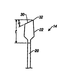
Referring to Figs. 1-4, a correction fluid container 10 includes a cap
12, an applicator 14, a body 16 including a correction fluid reservoir, and an
insert
CA 02328384 2004-03-26
WO 99/54151 PCT/US99/08610
-3-
18.
Applicator 14 includes a stem 20, and an applicator tip 22. The
applicator tip includes a foam portion 24 enclosing a flexor 26. The
applicator has
a flexibility of at least 0.0005 inch of deflection per gram of force,
preferably at
S least 0.002 inch of deflection per gram of force, measured as described
below. The
flexibility of the applicator depends on a number of factors, including the
stiffness
of the stem; the composition, length, width, and thickness of the flexor: and
the
chemical composition and thickness of the foam portion.
The stiffness of the stem depends on the composition, length. and
diameter of the stem. Generally, the less stiff the stem. the more flexible
the
applicator. Stems composed of softer materials are less stiff than stems
composed
of harder materials, and longer stems are less stiff than shorter stems. Stems
may
be made of, for example, polymeric materials such as a low density and/or high
density polyethylene or polypropylene. The stem may have a length. for
example,
of between 2 cm and 15 cm, and preferably between 2 cm and 10 cm. It also may
have a diameter of between, for example, 0.1 cm and 2 cm, and preferably
between
0.2 cm and 0.8 cm. Stem 20 has a length of 4.1 cm and a diameter of 0.31 em.
Flexor 26 includes an extension 28 that fits into the hollow end of
stem 20.
Generally, the softer the foam and the thinner the applicator tip the
greater the flexibility of the foam applicator. The foam may be, for example,
an
open cell foam having a pore size, for example, of between 20 ppi and 130 ppi,
preferably between 80 ppi and 120 ppi, and may be, for example, a
polyether/polyurethane, polyester/polyurethane, polyether, or polyester foam.
The
3
foam can have a density, for example, in the range of 1.G Ib/ft' to 15.0 lb/ft
, a
compression deflection (CLD) of 25% R (radius) at (0.05-5.0) psi and a CLD of
65% at (0.2-10) psi. A preferred foam is a quenched polyester polyurethane
foam
having a density of 1.85 lb/ft3, a pore size of 80 ppi to 120 ppi, a CLD of
25%
R at 0.25 psi, and a CLD of 65% R at 0.45 psi.
The foam portion (including the enclosed flexor) may have a
thickness (t,), for example, of between 0.16 cm and 1.27 cm, a length ( 1 ) of
between 0.3 cm and 2.0 cm, and a width (wl) between 0.2 cm and 1.0 cm. Foam
CA 02328384 2004-03-26
WO 99/54151 PCT/US99/08610
-4-
portion 24 has a thickness (t, ) (at midpoint) of about 0.44 cm, and a length
( I ) of
about 0.9 cm. Foam portion 24 is tapered and has a thickness at its base of
about
0.44 cm and a thickness towards its tip of about 0.34 cm.
Generally, the softer the composition of the flexor the greater the
flexibility of the foam applicator. The flexor may be composed, for example,
of a
composite of linear low density polyethylene and a thermoplastic olefin having
a
very high softness and low modules (e.g., AdflexTM ICS-359P, available from
Mobil),
low density polyethylene, high density polyethylene, polypropylene, or nylon.
In
addition, as a general rule, thinner flexors provide more flexible foam
applicators.
The flexor may have, for example, a width (w) of between 0.02 cm and 0.15 cm,
and a thickness (t) of between 0.1 cm and I.0 cm. Flexor 26 has a width (w) of
0.06 cm. Flexor 26 is tapered but has a thickness of about 0.2~ cm at its mid-
point.
Foam applicator 14 has an angled chisel-shaped applicator surface 30
that includes a point 32. The angle (a in the Figure) preferably is between I
S° and
60° (e.g., 30°). The tong applicator side surface can be used to
apply correction
fluid over words; the point or straight edge of 32 allows a user to easily
apply
correction fluid to individual letters.
Insert 18 may be composed, for example, of a high density
polyethylene. The insert has a narrowed neck region 30 that may have an inside
diameter of between 3.0 mm and 5.0 mm (e.g., 3.8 mm), and may have a length of
betv~~een 5 mm and 40 mm (e.g., 25 mm). When portion 24 is removed (wiped ofd
from the correction fluid reservoir for use, excess correction fluid is
removed by
narrowed neck. When portion 24 is reinserted into the fluid reservoir after
use,
any excess correction fluid that comes off portion 24 during reinsertion
generally is
accommodated by the portion of insert 18 above the narrowed neck, thus
avoiding
spillage of correction fluid.
Applicator 10 may be used with organic solvent-based or water-based
correction fluids. In addition to the liquid vehicle, correction fluids may
include an
opacifying agent such as titanium dioxide, a film-forming polymer, and various
other standard ingredients. Correction fluids may have a viscosity, for
example, of
between 10 cps and 2000 cps, preferably between 30 cps and 1000 cps, at 20 rpm
using a Brookfield Viscometer. Preferred correction fluids are described in,
for
CA 02328384 2004-03-26
WO 99/54151 PCT/US99/08610
_S_
example U.S. Patent Nos. 5,199,976 and 5,306,755.
Referring to Fig. 5, an applicator 34 has a design similar to applicator
14. Applicator 34, unlike applicator 14, does not have a tapered foam portion
or
tapered flexor.
Referring to Figs. 6 and 7, an alternative applicator 36 has a spear-
shaped tip and includes a stem 38, a flexor 40, and a foam portion 42.
The flexibility of an applicator can be measured using an Instron
Model 1122 Compression Tester. The capped end of the applicator is attached to
a
fixed stand, having a rotating fixture to vary the angle of attachment. The
angle is
set at 40° so that the foam-tip is just underneath the vertical
cylinder (probe) of the
tester, having a diameter of 15 cm. This probe is then moved downwards slowly
at
a controlled rate of 0.13 cmlmin while pressing the foam-tip during its
downward
movement. The force generated by the probe to deflect the foam-tip and the
actual
deflection of the foam-tip were continually monitored and transmitted to a
recorder
for recording on a X-Y graph. The flexibility (calculated from the graph)
corresponds to the ratio of deflection distance to the applied force, i.e.,
the slope of
deflection vs. applied force graph. The measurements are conducted at various
deflection distances, e.g., 0.05", 0.1 ", 0.15", 0.20" and 0.25".
The flexibility of 12 applicators was measured according to this
procedure. The results are shown below in Tables 1 and 2. "Spear" in the
applicator in Figs. 6 and 7; "Chisel #1" is the applicator in Figs. 1-4; and
"Chisel
#2" is the applicator in Fig. 5.
CA 02328384 2000-10-11
WO 99/54151 PCT/US99/08610
-6-
w w w w w w w w w w w w
a a a w a
~ a~ a~ a~a, a~ a~ s ~ a~ .. .
~ A A A A A A A A A A A A
x x a a a a x x a x a a
0 0
U U U U U ~' t'"~,"~"..~U 'C3
,
. . ~,
~ ~ ~ ~ ~ o o ~ ~ ~ w i
sz,~ a a a a a ~ ~ ~ ~ a o 0
_ _ _ _ a a a a _
\ \ \ \ \ \ \ \ \ 1 \ \
Gh M M M M M M M ~ ~ ~ ~ M ,~,,U
Cs.
Q" .~ ~, N
U
A A W ~ ~ A ~ ~ w
a a ~ a a a w
a a ~ a
p
0
.~ GH
o .-,
O ~ ~ O O O ~ O, N
w ~ ~ ~x is,~ ~ ~ ~ ~ -c ~
~ ~ d
a, r~.~ ~ -d -d ~ -a -o -d
0 0 d d ~ d d d
o ~ 0 0 0 ~ ~ 0 0 0 ~
4 k \ v \ -v
4: .~ .~ o o ~ ~ o o ~ O O O Q" ~ O
O O O O ~ O O O
w a, a....--,~ r..~, .-,,..~z ~ ~, ~., O ~ ~ a
~ b
_
,U
~ O
O
N d ~ ~ ~C P~tU A w w ~ o ~ '.'~.~
b
~ 'r'-~
r.U, ~ ~~ U
N
U 'ir~ O a
.
~ ~
b
N A ~ d
U ~ ~ ~ ~ ~ ~ V G) ~ ~ V
t
n
U U U U U U U U U U
N M ? ~ V1
p ~ Q
CA 02328384 2000-10-11
WO 99/54151 PCTNS99/08610
~ ~nO~ N
C~
O~N ~Y
N V'7~O C1 M N ~..~~O00 N
d' ~ o 0 0 O~
00 ~ N d'
""' 0 0 0 0
O 0
0
0
O O O O O O O O O
O
O O CO O O
W lp M ~ 'd' M M 00 ~ 00
M M M '~ ~-~ ~-~ N O ~'
O O O O O ~ ~ ~ O O O
O O O O O
O O O O O
A ~ oNON ~ v~
00 ~ ~n N
l~ ~ W O ~O N 00 N
.~~p O O O O O ,'X,' 0 0
0 0 0 0 0 p 0 0
O O O O O
N
w
U
~ N ~ o0o
Q _ _ O O ~--~M M t~
O O
.. O O CO O O '-'O M v1
fT M ~!1
~ 3 0 0 0 0
E-~ 0
b
0 0 0 0 0
0
l~ ~O O~OvN1N
V I~ ~_1I_~0_00_~
v O O O O O
O O O O O
O O O O CO
M N O~
n N n
N ~
v1l~ ~O ~n ~t
O O O O O
O O O O O
a
O O
O O O
O O O O O
O O C O CO
n N O~ f~
~O O ~O M
~O 00 00
~ N .-n .-.
O ~ O O O O O
V ~ O O O O O
N
U p .--~ ~ N N
~ O O O O O
V7 O ~1
CA 02328384 2000-10-11
WO 99/54151 PCT/US99/08610
_g_
Although the flexibility of the examples were measured at various
deflection distances, '.'flexibility"(as that term is used in the claims)
should be
measured at a deflection distance of 0.05".