Language selection

Search

Patent 2328683 Summary

Third-party information liability

Some of the information on this Web page has been provided by external sources. The Government of Canada is not responsible for the accuracy, reliability or currency of the information supplied by external sources. Users wishing to rely upon this information should consult directly with the source of the information. Content provided by external sources is not subject to official languages, privacy and accessibility requirements.

Claims and Abstract availability

Any discrepancies in the text and image of the Claims and Abstract are due to differing posting times. Text of the Claims and Abstract are posted:

  • At the time the application is open to public inspection;
  • At the time of issue of the patent (grant).
(12) Patent: (11) CA 2328683
(54) English Title: SINGLE-BOLT BAR-BRACKET MOUNT
(54) French Title: BARRE SUPPORT A BOULON UNIQUE
Status: Expired
Bibliographic Data
(51) International Patent Classification (IPC):
  • B62D 25/18 (2006.01)
(72) Inventors :
  • HAWES, TIMOTHY R. (United States of America)
(73) Owners :
  • FLEET ENGINEERS, INCORPORATED (United States of America)
(71) Applicants :
  • FLEET ENGINEERS, INCORPORATED (United States of America)
(74) Agent: BORDEN LADNER GERVAIS LLP
(74) Associate agent:
(45) Issued: 2008-03-18
(22) Filed Date: 2000-12-18
(41) Open to Public Inspection: 2001-06-21
Examination requested: 2005-11-16
Availability of licence: N/A
(25) Language of filing: English

Patent Cooperation Treaty (PCT): No

(30) Application Priority Data:
Application No. Country/Territory Date
60/171,398 United States of America 1999-12-21

Abstracts

English Abstract

The invention relates to a bracket-mounting assembly for mounting a bar bracket to a vehicle frame, the bar bracket being adapted to carry vehicle accessories such as a mudflap. The bracket-mounting assembly attaches to a vehicle frame via a single bolt passed through a penetration in the vehicle frame and threadably connected to the bracket-mounting assembly by a central threaded hole in the bracket-mounting assembly. The bracket-mounting assembly further includes a generally vertically-oriented shaft opening for receiving a portion of the bar bracket and supporting the bar bracket with respect to the vehicle frame. The bracket-mounting assembly includes a rotation-resisting connector for inhibiting rotation of the bracket-mounting assembly relative to the vehicle frame about the axis of the bolt.


French Abstract

L'invention concerne une ferrure servant au montage d'une barre de support sur le châssis d'un véhicule, la barre de support étant conçue pour le transport d'accessoires tels qu'une bavette garde-boue. La ferrure se fixe au châssis du véhicule à l'aide d'un unique boulon introduit dans un trou percé dans le châssis du véhicule et vissé dans le trou central fileté de la ferrure. La ferrure comprend également une ouverture d'axe dont l'orientation est généralement verticale et qui sert à recevoir une partie de la barre de support en vue de soutenir celle-ci relativement au châssis du véhicule. La ferrure comprend enfin un raccord contrarotatif servant à prévenir la rotation de la ferrure autour de l'axe du boulon par rapport au châssis du véhicule.

Claims

Note: Claims are shown in the official language in which they were submitted.


CLAIMS

What is claimed is:


1. A bracket-mounting assembly for mounting a mudflap bracket to a vehicle
frame, comprising:
a body having a frame-mounting portion and a bracket-mounting portion,
the frame-mounting portion having a frame face at one side of the frame-
mounting portion adapted to abut the vehicle frame and a lateral hole
transverse to the
frame face; and
the bracket-mounting portion having a vertically-extending shaft opening
extending at least a portion of the way through the body for removably
mounting the
mudflap bracket;
at least one pin mounted in the frame-mounting portion and projecting from the

frame face for gripping a surface of the vehicle frame to resist relative
rotation of the
body with respect to the vehicle frame; and
a bolt received in the lateral hole in the frame-mounting portion for securing
the
body to the frame.


2. The bracket-mounting assembly of claim 1, wherein the lateral hole is
tapped and the bolt is threadably received in the lateral hole.


3. The bracket-mounting assembly of claim 1, wherein the vertically-
extending shaft extends through the bracket-mounting portion.


4. The bracket-mounting assembly of claim 1, wherein there are multiple
pins mounted in the frame-mounting portion.


5. The bracket-mounting assembly of claim 4, wherein the pins are spaced
about the lateral hole.


-5-


6. The bracket-mounting assembly of claim 4, wherein the pins have a
pointed end to bite into the vehicle frame.


7. The bracket-mounting assembly of claim 4, wherein the pins are
positioned in wells in the frame-mounting portion.


8. The bracket-mounting assembly of claim 1, wherein the at least one pin
has a pointed end to bite into the vehicle frame.


9. The bracket-mounting assembly of claim 1, wherein the body is a casting.

10. A bracket-mounting assembly for mounting a mudflap bracket to a vehicle
frame, comprising:

a body having a frame-mounting portion and a bracket-mounting portion,
the frame-mounting portion having a frame face at one side of the frame-
mounting portion adapted to abut the vehicle frame and a tapped lateral hole
transverse to
the frame face and

the bracket-mounting portion having a vertically-extending shaft opening
extending at least a portion of the way through the body for removably
mounting the
mudflap bracket;

a bolt threadably received in the tapped lateral hole in the frame-mounting
portion
for securing the body to the frame; and

a rotation-resisting connector on the frame-mounting portion adapted to
interface
with the vehicle frame to resist relative rotation of the body with respect to
the vehicle
frame about the axis of the bolt.


11. The bracket-mounting assembly of claim 10, wherein the vertically-
extending shaft extends through the bracket-mounting portion.


12. The bracket-mounting assembly of claim 10, wherein the rotation-resisting
connector comprises at least one pin mounted in the frame-mounting portion.


-6-


13. The bracket-mounting assembly of claim 12, wherein there are multiple
pins mounted in the frame-mounting portion.


14. The bracket-mounting assembly of claim 13, wherein the pins are spaced
about the tapped lateral hole.


15. The bracket-mounting assembly of claim 13, wherein each pin has a
pointed end to bite into the vehicle frame.


16. The bracket-mounting assembly of claim 13, wherein the pins are
positioned in wells in the frame-mounting portion.


17. The bracket-mounting assembly of claim 12, wherein the at least one pin
has a pointed end to bite into the vehicle frame.


18. The bracket-mounting assembly of claim 10, wherein the body is a casting.


-7-

Description

Note: Descriptions are shown in the official language in which they were submitted.


CA 02328683 2000-12-18

SINGLE-BOLT BAR-BRACKET MOUNT

BACKGROUND OF THE INVENTION
Field of the Invention
The invention relates to a bracket mount for mounting a bar bracket to a
vehicle frame, the bar bracket being adapted to carry vehicle accessories such
as a
mudflap.

Description of the Related Art
Bar brackets are typically mounted to a vehicle frame with a mount
comprising a flat plate mated to the vehicle frame, and secured thereto with,
typically,
two or four mechanical fasteners, requiring an equal number of properly
aligned
penetrations through the vehicle frame. A body extending from the flat plate,
and having
a square aperture passing therethrough, is adapted to receive the square cross-
section of
the typical solid bar bracket.

SUMMARY OF THE INVENTION
According to the invention, a bracket-mounting assembly for mounting a
mudflap bracket to a vehicle frame comprises a body having a frame-mounting
portion
and a bracket-mounting portion, the frame-mounting portion having a frame face
at one
side of the frame-mounting portion adapted to abut the vehicle frame and a
lateral hole
transverse to the frame face and the bracket-mounting portion having a
vertically-
extending shaft opening extending at least a portion of the way through the
body for
removably mounting the mudflap bracket; at least one pin mounted in the frame-
mounting portion and projecting from the frame face for impinging on a surface
of the
vehicle frame to resist relative rotation of the body with respect to the
vehicle frame; and

-1-


CA 02328683 2000-12-18

a bolt received in the lateral hole in the frame-mounting portion for securing
the body to
the frame.

In one embodiment, the lateral hole is tapped and the bolt is threadably.
received in the lateral hole. Preferably, the vertically-extending shaft
extends through the
bracket-mounting portion. In a preferred embodiment, there are multiple pins
mounted in
the frame-mounting portion and the pins are spaced about the lateral hole.
In another of its aspects, the invention relates to a bracket-mounting
assembly
for mounting a mudflap bracket to a vehicle frame comprising a body having a
frame-mounting portion and a bracket-mounting portion, the frame-mounting
portion
having a frame face at one side of the frame-mounting portion adapted to abut
the vehicle
frame and a tapped lateral hole transverse to the frame face and the bracket-
mounting
portion having a vertically-extending shaft opening extending at least a
portion of the way
through the body for removably mounting the mudflap bracket; a bolt threadably
received
in the tapped lateral hole in the frame-mounting portion for securing the body
to the
frame; and a rotation-resisting connector on the frame-mounting portion
adapted to
interface with the vehicle frame to resist relative rotation of the body with
respect to the
vehicle frame about the axis of the bolt.

BRIEF DESCRIPTION OF THE DRAWINGS
In the drawings:

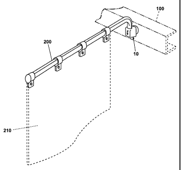
FIG. 1 is perspective view of the single-bolt bar-bracket mount according to
the invention, mounted to a vehicle frame, and carrying a bar bracket;

FIG. 2 is a perspective view of the bracket mount of FIG. 1;

FIG. 3 is a reverse perspective view of the bar-bracket mount of FIG. 1;
FIG. 4 is a top view of the bar-bracket mount of FIGS. 1 and 2; and

FIG. 5 is a cross-sectional view of the bar-bracket mount, taken along line 5-
5
of FIG. 4.

-2-


CA 02328683 2000-12-18

DESCRIPTION OF THE PREFERRED EMBODIMENT

Figure 1 depicts the bar-bracket mount 10 according to the invention installed
on a vehicle frame 100 and carrying a typical bar bracket 200 for a mudflap
210. The bar
bracket 200 and the mudflap 210 are conventional and form no part of the
invention.
Referring now to FIGS. 2 and 3, the bar-bracket mount 10 is comprised of two
body
portions. A first cylindrical portion 20 comprises a solid body 22 with a
threaded shaft 24
centered on the longitudinal axis of the cylindrical portion 20. The second
body portion
30 is a solid of generally trapezoidal cross section. The width of the base 32
of the second
body portion 30 is generally equal to the diameter of the cylindrical portion
20. The base
32 is connected to one end of the cylindrical portion 20. The portions 20, 30
are

preferably unitary, as in a casting, but can be formed separately and
connected in a
conventional manner such as by welding. The bar bracket mount is preferably
made of
steel or other high strength metal.
As seen in FIG. 3, the cylindrical portion 20 of the bar-bracket mount 10
further comprises a plurality of wells 26 set into a face 28 of the body 22 of
the -
cylindrical portion 20. As better seen in FIG. 4, these wells 26 are parallel
to the
longitudinal shaft 24. Each of the wells 26 is adapted to receive a steel pin
40. Each steel
pin 40 has an end 42 that protrudes from the well 26, away from face 28 of the
cylindrical
portion 20, opposite the second body portion 30. The steel pins 40 are adapted
to
impinge upon a surface of the vehicle frame 100, against which the face 28 of
the bar
bracket mount 10 is placed. The longitudinal threaded shaft 24 of the
cylindrical portion
20 is shown in shadow in FIG. 4, aligned but transverse to a square shaft
opening 34 that
passes through the second body portion 30 of the bar-bracket mount 10. This
relationship
is better shown in FIG. 5, a cross section through line 5-5 of FIG. 4. The
longitudinal

shaft 24 of the cylindrical portion 20 is of limited depth and does not pass
into the
opening 34 of the second body portion 30 of the bar-bracket mount 10.
In use, the bar-bracket mount 10 is aligned with a generally horizontal
opening
102 through a vehicle frame 100, and a threaded bolt 104 is passed through the
opening
102 in the vehicle frame 100 and into the threaded shaft 24. The threaded bolt
104, of

-3-


CA 02328683 2000-12-18

necessity, will be of a length such that, upon passing through the vehicle
frame 100 and
into the shaft 24 of the bar-bracket mount 10, it will not bottom out in the
shaft 24 of the
bar-bracket mount 10, but will draw the face 28 fast against the vehicle frame
100, with
the end 42 of each steel pin 40 impinging upon and gripping the surface of the
vehicle

frame 100. During installation, the installer will ensure that the square
shaft opening 34
of the second body portion 30 of the bar-bracket mount 10 is given the proper
orientation,
i.e. vertical, before tightening the single bolt 104 that secures the bar-
bracket mount 10 to
the vehicle frame 100.

The single bolt bar-bracket mount 10 therefore provides the advantage of
maintaining a bar bracket 200 and associated mudflap 20 in the proper
orientation with
respect to a vehicle frame 100, i.e. vertically, while also presenting the
advantage of
limiting the number of penetrations through the vehicle frame 100, thereby
simplifying
and speeding installation. It further eliminates the requirement that a bar-
bracket mount
have multiple openings properly configured to match the multiple penetrations
existing in
the vehicle frame.

While the invention has been specifically described in connection with certain
specific embodiments thereof, it is to be understood that this is by way of
illustration and
not of limitation. Reasonable variation and modification are possible within
the scope of
the forgoing description and drawings without departing from the spirit of the
invention.

-4-

Representative Drawing
A single figure which represents the drawing illustrating the invention.
Administrative Status

For a clearer understanding of the status of the application/patent presented on this page, the site Disclaimer , as well as the definitions for Patent , Administrative Status , Maintenance Fee  and Payment History  should be consulted.

Administrative Status

Title Date
Forecasted Issue Date 2008-03-18
(22) Filed 2000-12-18
(41) Open to Public Inspection 2001-06-21
Examination Requested 2005-11-16
(45) Issued 2008-03-18
Expired 2020-12-18

Abandonment History

There is no abandonment history.

Payment History

Fee Type Anniversary Year Due Date Amount Paid Paid Date
Application Fee $300.00 2000-12-18
Registration of a document - section 124 $100.00 2001-12-11
Maintenance Fee - Application - New Act 2 2002-12-18 $100.00 2002-12-17
Maintenance Fee - Application - New Act 3 2003-12-18 $100.00 2003-12-17
Maintenance Fee - Application - New Act 4 2004-12-20 $100.00 2004-12-17
Request for Examination $800.00 2005-11-16
Maintenance Fee - Application - New Act 5 2005-12-19 $200.00 2005-12-16
Maintenance Fee - Application - New Act 6 2006-12-18 $200.00 2006-12-15
Final Fee $300.00 2007-10-22
Maintenance Fee - Application - New Act 7 2007-12-18 $200.00 2007-12-17
Maintenance Fee - Patent - New Act 8 2008-12-18 $200.00 2008-12-17
Maintenance Fee - Patent - New Act 9 2009-12-18 $200.00 2009-12-17
Maintenance Fee - Patent - New Act 10 2010-12-20 $250.00 2010-12-17
Maintenance Fee - Patent - New Act 11 2011-12-19 $250.00 2011-12-16
Maintenance Fee - Patent - New Act 12 2012-12-18 $250.00 2012-12-17
Maintenance Fee - Patent - New Act 13 2013-12-18 $250.00 2013-12-17
Maintenance Fee - Patent - New Act 14 2014-12-18 $250.00 2014-12-17
Maintenance Fee - Patent - New Act 15 2015-12-18 $450.00 2015-12-17
Maintenance Fee - Patent - New Act 16 2016-12-19 $450.00 2016-12-16
Maintenance Fee - Patent - New Act 17 2017-12-18 $450.00 2017-12-15
Maintenance Fee - Patent - New Act 18 2018-12-18 $450.00 2018-12-18
Maintenance Fee - Patent - New Act 19 2019-12-18 $450.00 2019-12-17
Owners on Record

Note: Records showing the ownership history in alphabetical order.

Current Owners on Record
FLEET ENGINEERS, INCORPORATED
Past Owners on Record
HAWES, TIMOTHY R.
Past Owners that do not appear in the "Owners on Record" listing will appear in other documentation within the application.
Documents

To view selected files, please enter reCAPTCHA code :


To view images, click a link in the Document Description column. To download the documents, select one or more checkboxes in the first column and then click the "Download Selected in PDF format (Zip Archive)" or the "Download Selected as Single PDF" button.

List of published and non-published patent-specific documents on the CPD .

If you have any difficulty accessing content, you can call the Client Service Centre at 1-866-997-1936 or send them an e-mail at CIPO Client Service Centre.


Document
Description 
Date
(yyyy-mm-dd) 
Number of pages   Size of Image (KB) 
Cover Page 2001-06-22 1 32
Representative Drawing 2001-06-22 1 4
Abstract 2000-12-18 1 24
Description 2000-12-18 4 177
Claims 2000-12-18 3 90
Drawings 2000-12-18 2 32
Representative Drawing 2008-02-15 1 6
Cover Page 2008-02-15 2 39
Correspondence 2001-01-26 1 24
Assignment 2000-12-18 3 77
Correspondence 2001-02-05 2 86
Assignment 2001-12-11 5 264
Prosecution-Amendment 2005-11-16 1 19
Prosecution-Amendment 2006-01-09 1 29
Correspondence 2007-10-22 1 30