Note: Descriptions are shown in the official language in which they were submitted.
CA 02328736 2000-12-19
- 1 -
LIGHT CONTROL TYPE LED LIGHTING EQUIPMENT
BACKGROUND OF THE INVENTION
Field of the Invention
The present invention relates generally to a lighting
equipment to be used in a home, an office, a shop or the like.
More particularly, the invention relates to a light control
type LED lighting equipment driving LEDs with receiving power
from an alternating current power source for serving as a light
source.
Description of the Related Art
Since high-intensity blue LEDs have been put into practice,
blue LEDs, red LEDs and green LEDs are aggregatedly mounted
for forming a general lighting equipment similarly to a
fluorescent lamp, a filament lamp and so forth. A lighting
equipment employing LED aggregate lamps is particularly
advantageous in comparison with existing fluorescent lamp,
filament lamp and so forth for long life time and low power
consumption. One of the advantages of the LED lamp is capability
of freely varying color of a light emitted therefrom. Namely,
by forming the lamp by aggregating LEDs of three primary colors
and constructing a circuit for independently varying luminance
of respective LED groups of three primary colors, a color tone
of the light can be varied in a wide range.
In the lighting equipment with the LED aggregate lamp,
CA 02328736 2000-12-19
- 2 -
a blue color adjusting knob variably adjusting luminance of
the blue LEDs, a red color adjusting knob variably adjusting
luminance of the red LEDs and a green color adjusting knob variably
adjusting luminance of the green LEDs are provided. In this
case, by variably operating the three adjusting knobs, the color
tone of the light can be varied arbitrarily.
Usability of the light adjusting type lighting equipment
is now considered. Consideration is given for the case where
the light adjusting type lighting equipment is used in a
supermarket for lighting goods/articles in the store. An owner
or manager of the shop may attempt to promote willingness to
buy of the customer by skillfully using sense of color given
by the light from the equipment to a human. Therefore, for
example, appropriate light may be employed which will match
colors of respective goods/articles, such as by lighting a meet
with reddish white color, by lighting a vegetable with bluish
white color . However, it is dif f icult to obtain des fired delicate
color tone by combination of three primary colors such as "reddish
white color", "bluish white color" and so forth, with three
adjusting knobs. The reason is that patterns of combination
by three adjusting knobs are present in .infinite number. This
is equally applicable as lighting for a living room at home,
mood lighting in a shop of bar, club or the like.
On the other hand, by using high level concept, such as
color difference and so forth, it has been considered to reduce
CA 02328736 2000-12-19
- 3 -
number of adjusting knobs. However, such a concept as "color
difference" is too technical for general users to understand
real feeling in light adjustment. It is further difficult to
reproduce the same condition in light adjustment.
On the other hand, there is a system, in which several
tones are preliminarily prepared and a desired tone is
appropriately selected by the user. However, sense of color
in the provided tone is discrete and cannot express delicate
tone.
Furthermore, an operation input portion,such asadjusting
knobs for respective lighting colors are often secured on a
wall or the like to degrade convenience in adjustment. It would
be desirable to adjust the lighting color in the sense as varying
television channel by remote control operation.
SUMMARY OF THE INVENTION
The present invention has been worked out for solving
the shortcoming in the prior art. Therefore, an object of the
present invention is to provide a LED lighting equipment which
can be simply perform lighting control of the light by any body
and can obtain wide variety of tones in wide range by merely
operating one operation knob on a remote controller variably.
According to one aspect of the present invention, a light
control type LED lighting equipment comprises:
a LED aggregate lamp portion, in which a first color LED
group, a second color LED group and a third color LED group
CA 02328736 2000-12-19
- 4 -
are included;
an alternating current power connecting portion for being
connected to a power source;
a power source converting portion for rectifying an
alternating current power received through the alternating
current power connecting portion;
a first color drive circuit, a second color drive circuit
and a third color drive circuit for supplying power for respective
of the first color LED group, the second color LED group and
the third color LED group by an output of the power source
converting portion so as to illuminate the LED groups;
control input generating means for generating one series
of control input signal, a value of the control input signal
increasing or decreasing within a predetermined range in
response to operation by a user;
control output generating means for generating a
combination of first color luminance data, a second color
luminance data and a third color luminance data corresponding
to a value of the control input signal according to a
predetermined characteristics; and
individual power control means for independently
controlling the first color drive circuit, the second color
drive circuit and the third color drive circuit on the basis
of the first color luminance data, the second color luminance
data and the third color luminance data for varying power supply
CA 02328736 2000-12-19
- 5 -
amount for the first LED group, the second LED group and the
third LED group,
a color tone of the LED aggregate lamp portion being varied
continuously depending on the value of the control input signal
according to a predetermined primary curve set in a chromaticity
coordinate.
The light control type LED lighting equipment may further
comprises:
second control input generating means for generating one
series of second control signal, a value of the second signal
increasing or decreasing within a predetermined range by
operation of the user;
common power control means for uniformly varying power
supply amount for the f first color LED group, the second color
LED group and the third color LED group by uniformly increasing
or decreasing amount of current value of the first color drive
circuit, the second color drive circuit and the third color
drive circuit depending upon a value of the second control input
signal,
2 0 the hue of the LED aggregate lamp substantially maintained
while brightness of the lighting is varied.
The first color drive circuit, the second color drive circuit
and the third color drive circuit may be constant current type,
and the individual power control means individually varies power
supply amount for the first color LED group, the second color
CA 02328736 2000-12-19
_ 6 _
LED group and the third color LED group by a pulse width modulation
method.
The light control type LED lighting equipment may further
comprises:
second control input generating means for generating one
series of second control signal, a value of the second control
signal increasing or decreasing within a predetermined range
by operation of the user;
common power control means for 'uniformly varying power
supply amount for the first color LED group, the second color
LED group and the third color LED group by varying output from
the power source converting portion depending upon a value of
the second control input signal,
the hue of the LED aggregate lamp substantially maintained
while brightness of the lighting is varied.
The LED aggregate lamp portion, the alternating current
power connecting portion, the power source converting portion,
the first color drive circuit, the second color drive circuit,
the third color drive circuit, the control output generating
means including a control signal receiving portion and the
individual power control means are mounted on the lighting
equipment main body, the control input generating means
including a control signal transmitting portion is mounted on
a remote controller separated from the main body, the control
signal transmitting portion being connected to the control
CA 02328736 2000-12-19
_ 7 _
signal receiving portion through a ratio transmission line.
According to another aspect of the present invention,a
light control type LED lighting equipment comprises:
a LED aggregate lamp portion, in which a first color LED
group, a second color LED group and a third color LED group
are included;
a first color drive circuit, a second color drive circuit
and a third color drive circuit for supplying power for respective
of the first color LED group, the second color LED group and
the third color LED group so as to illuminating the LED groups;
control input generating means for generating one series
of control input signal, a value of the control input signal
increasing or decreasing within a predetermined range in
response to operation by a user;
control output generating means for generating a
combination of first color luminance data, a second color
luminance data and a third color luminance data corresponding
to a value of the control input signal according to a
predetermined primary curve set in a chromaticity coordinate;
and
individual power control means for independently
controlling the first color drive circuit, the second color
drive circuit and the third color drive circuit on the basis
of the first color luminance data, the second color luminance
data and the third color luminance data for varying power supply
CA 02328736 2000-12-19
_ g _
amount for the first LED group, the second LED group and the
third LED group,
wherein a color tone of the LED aggregate lamp portion
being varied continuously depending on the value of the control
input signal.
BRIEF DESCRIPTION OF THE DRAWINGS
The present invention will be understood more fully from
the detailed description given hereinafter and from the
accompanying drawings of the preferred embodiment of the present
invention, which, however, should not be taken to be limitative
to the invention, but are for explanation and understanding
only.
In the drawings:
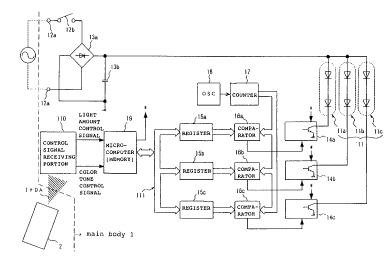
Fig. 1 is a block diagram showing a general circuit diagram
of one embodiment of a light control type LED lighting equipment
according to the present invention;
Fig. 2 is a xy chromaticity diagram generally showing
a primary curve relating to one embodiment of the present
invention; and
Fig. 3 is a general illustration of the primary curve
of spiral shape relating to one embodiment of the present
invention.
DESCRIPTION OF THE PREFERRED EMBODIMENT
The present invention will be discussed hereinafter in
detail in terms of the preferred embodiment of the present
CA 02328736 2000-12-19
- 9 -
invention with reference to the accompanying drawings. In the
following description, numerous specific details are set forth
in order to provide a thorough understanding of the present
invention. It will be obvious, however, to those skilled in
the art that the present invention may be practiced without
these specific details. In other instance, well-known
structures are not shown in detail in order to avoid unnecessary
obscurity of the present invention.
Fig. 1 is a circuit diagram of one embodiment of a light
control type LED lighting equipment according to the present
invention. The LED lighting equipment has a main body having
a LED aggregate lamp portion 11 as a light source and a remote
controller 2 communicating with the main body 1 through a radio
transmission line.
The LED aggregate lamp portion 11 is formed by installing
a red LED group lla, a green LED group llb and a blue LED group
llc to form an optical system dispersing a light well admixed
red, green and blue lights. Electrically, a large number of
red LEDs are appropriately connected in series and/or parallel
to form the red LED group lla. Also, a large number of green
LEDs are appropriately connected in series and/or parallel to
form the green LED group llb, and a large number of blue LEDs
are appropriately connected in series and/or parallel to form
the blue LED group llc.
An alternating current power source connecting portion
CA 02328736 2000-12-19
- 10 -
of the main body 1 is a power source plug 12a adapted to a consent
of generally 100V of commercial alternating current power source .
By connecting the power source plug 12a to the effective power
source consent and turning ON the power source switch 12b, an
alternating current power is applied to a power source converting
portion including a diode bridge rectifier circuit 13a and a
capacitor 13b for rectification and smoothing to convert into
a direct current power source. To an output of the power source
converting portion, the red LED group lla, the green LED group
l lb and the blue LED group l lc forming the aggregate lamp portion
11 are connected in parallel . A red driving circuit for applying
power for illuminating the red LEDs in the red LED group lla
is connected to the direct current power source line of the
red LED group lla. Similarly, a green driving circuit for
applying power for illuminating the green LEDs in the green
LED group llb is connected to the direct current power source
line of the green LED group llb, and a blue driving circuit
for applying power for illuminating the blue LEDs in the blue
LED group llc is connected to the direct current power source
line of the blue LED group l lc . By connecting the driver circuits
for respective colors of LED groups, a driving system for
driving respective colors of LED groups for illumination is
constructed. The driver circuits for respective colors
comprise constant current type drivers 14a, 14b and 14c,
registers 15a, 15b and 15c and comparators 16a, 16b and 16c,
CA 02328736 2000-12-19
- 11 -
and are connected to an oscillation circuit 18 via a counter
17. Components and operation of the driving system will be
discussed in detail.
A main component in a processing system of the main body
1 is a microcomputer 19 including a built-in memory. The
microcomputer 19 has an input connected to a control signal
receiving portion 110 and an output connected to the driving
system via a bus 111 . A controller 2 transmits a control signal
to the control signal receiving portion 110.
The remote controller 2 has a liquid crystal display
portion of character display on the surface of a casing, an
operation input portion for input operation by the user, a control
signal transmitting portion transmitting a control signal as
IrDA for illumination of the main body on the basis of an input
through the operation input portion signal and a microcomputer
connected to these components through bus for concentrated
control.
The operation input portion has a first control input
generating means and a second control input generating means .
These control input generating means are comprised of a plurality
of buttons and knobs for being operated by the user, and a variable
resistor or a rotary encoder for lighting adjustment. Each of
these control generating means generates one series of control
input signals, the values of which increase and decrease within
predetermined ranges.
CA 02328736 2000-12-19
- 12 -
The first control input generating means is means for
inputting a command for independently controlling luminance
of the red LED group lla, the green LED group llb and the blue
LED group llc to generate a color tone input signal (hereinafter
referred to as color tone input means ) . The second control input
generating means is means for inputting command for uniformly
controlling luminance (brightness) of the LED aggregate lamp
and generating a
light amount input signal (hereinafter referred to as light
10 amount input means). Next, discussion will be given for
controlling driving of the LED groups on the basis of these
input signals.
«LED Group Drive Control»
When the user performs predetermined input operation with
15 watching, for example, alphanumeric characters displayed on
the liquid crystal display portion by the light amount and color
tone control input means, the microcomputer of the controller
2 sets the light amount and the color tone input signals generated
in response to the input operation . Then, when the user performs
predetermined operation, the microcomputer transmits IrDA
signal corresponding to the set input signal to the control
signal receiving portion 110 of the main body 1.
The microcomputer 19 of the main body 1 individually
processes the received IrDA signal as the light control signal
and the color tone control signal.
CA 02328736 2000-12-19
- 13 -
The light amount control signal is input to the
microcomputer 19 as a common s ignal to a current setting terminals
of the respective drivers 14a, 14b and 14c. By uniformly
increasing or decreasing the current value flowing through
respective drivers 14a, 14b and 14c depending upon the light
amount control signal, the supply power to the respective LED
groups lla, llband llc increases or decreases uniformly. Namely,
by input operation from the light amount input means of the
remote controller 2, the luminance level of the LED groups lla,
llb and llc is varied uniformly.
In the shown embodiment, independently of uniform control
of luminance, the luminance level of each of the LED groups
lla, llb and llc can be controlled independently of each other.
This color tone control is performed by a pulse width modulation
method on the basis of the color tone control signal as another
control signal. Namely, the color tone control signal is input
to an A/D converter terminal of the microcomputer. Then,
predetermined conversion process is performed to output 8-bit
red luminance data, green luminance data, blue luminance data
as converted outputs to be a base of luminance level control.
Respective registers 15a, 15b and 15c latch the red luminance
data, the green luminance data and the blue luminance data.
The 8-bit red luminance data, green luminance data, blue
luminance data thus latched become data for determining pulse
width of the drive pulse for driving the red LED group lla,
CA 02328736 2000-12-19
- 14 -
the green LED group l lb and the blue LED group 1 lc for illumination
at respectively independent luminance level. The driving
system for respective of three primary colors of RGB is identical
with each other. Therefore, the follawing discussion will be
given for the control system of the red color illumination as
an illustration.
By the oscillation circuit 18, sufficiently high constant
frequency of clock pulses are continuously generated. By the
clock pulse, scale-of-256 (= 28) counter 17 is incremented to
repeatedly vary the 8-bit counted value of the counter from
all "0" to all "1" with a given period Ts. By comparing the
8-bit counted value with the 8-bit level data latched by the
register 15a by a digital comparator 16a, a drive pulse
corresponding to 8-bit level data corresponding to the pulse
width Tw and the period being Ts, is output from the digital
comparator 16a. Namely, the driver 14a supplies a given current
for the red LEDs for the period corresponding to the pulse width
Tw of the drive pulse for illuminating the red LEDs . This pulse
illumination is repeated at a period Ts.
As set forth above, by input operation from the color
tone input means of the remote controller 2, luminance levels
of respective colors of LED groups lla, llb and llc are varied
independently. The process for converting the color tone
control signal input to the A/D conversion terminal of the
2 5 microcomputer 19 into the red luminance data, the green luminance
CA 02328736 2000-12-19
- 15 -
data and the blue luminance data is particular feature of the
invention. Therefore, conversion process will be discussed.
«Generation of Luminance Data for Each Color»
The microcomputer 19 digitizes an analog color tone
control signal input to the A/D conversion terminal at 256 levels
depending upon magnitude of the color tone control signal . The
digital value thus converted into the corresponding level is
stored as color tone parameter in an address space prepared
for color tone parameter. The microcomputer 19 executes a
predetermined logic program stored in a memory with taking the
color tone parameter as input to obtain a coordinate value (Y,
x, y ) on a primary curve preliminarily determined by chromaticity
coordinates. Subsequently, the microcomputer 19 further
executes the logic program to obtain :respectively 8-bit data
of the red color luminance, the green color luminance and the
blue color luminance on the basis of three coordinate values
Y, x, y. These luminance data is output to the drive system
as set forth above.
In the shown embodiment, the chromaticity coordinate is
a spatial coordinate system formed by overlaying a plurality
of the same luminance surfaces (xy chromaticity chart) in
luminance axis direction. By the coordinate value (Y, x, y)
at certain one point in the coordinate system, these attribute
of the color (brightness, hue and richness of the color) are
determined in unambiguous manner. Y corresponds to the
CA 02328736 2000-12-19
- 16 -
brightness of the color, and ( x, y ) correspond to hue and richness
of the color respectively. On the other hand, the primary curve
is an arbitrary sequential curve function arranged in the
chromaticity coordinates, in which three coordinate values Y,
x and y are provided for one input value ( = value of color tone
designating parameter). As a particular example, a primary
curve on a xy chromaticity chart of the luminance value YO is
shown in Fig. 2. According to the primary curve f(k) of Fig.
2, as the color tone designation parameter k increases from
0 to 255, the color tone is varied continuously, such as "pinky
white color" ~ "greenish white color" ~ "bluish white color".
By varying the color tone continuously, such an intermediate
color as one between "pinky white color" and "greenish white
color" and other delicate color tones can be expressed. BY
preparing a plurality of patterns of the primary curve f(k)
and storing in the memory of the microcomputer 19, desired color
tone may be selected depending upon application, time, season
and so forth to permit light control to be done more easily
and with a wider variation.
On the other hand, by establishing the primary curve in
spiral form expanding in the luminance direction, a plurality
of mutually distinct combinations of luminance values and the
color tone can be provided continuously with one parameter.
For example, it becomes possible to express various colors from
"bright bluish white color" to "dark reddish white color. Sense
CA 02328736 2000-12-19
- 17 -
of color corresponding to the curve varies from "beamish" to
"calm". By preparing a plurality of patterns of the primary
curve f ( k ) and storing them in the memory of the microcomputer
19 , des fired color tone may be selected depending upon application,
time, season and so forth, lighting closely f fitting to preference
desire of the user becomes possible. On the other hand, in
viewpoint of the hardware, elements associated with the light
amount input means are integrated with the color tone input
means, overall construction of the lighting equipment can be
significantly simplified.
Furthermore, by taking a time t: as a parameter for the
primary curve ( see Fig . 3 ) , a timer function ( or simple scheduling
function ) may be added to the lighting equipment, such as varying
the luminance and the color tone along a predetermined zone
of the curve in a predetermined unit time period. For example,
by employing this function in lighting i.n a bed room, comfortable
sleep may be attained in continuously changing mood. Also, by
setting to automatically turn off the light after a certain
time period, it may contribute to power saving. Also, in a night
club, by automatically varying the lighting from "stimulating
lighting" -~ "calm lighting" ~ "lighting encouraging returning
home" so that the customer enjoy a given time and turning over
ratio of the customer can be improved.
«Modif ications»
As a second embodiment of the present invention, a common
CA 02328736 2000-12-19
- 18 -
power control means may be provided at the downstream side of
the power source converting portion. The microcomputer 19
controls the common power control means on the basis of the
light amount control signal originated by input operation
through the light amount input means of the remote controller
2. Namely, if the light amount control signal is "small", the
output of the power source converting means is lowered by the
common power control means, and otherwise, the output is
increased. Accordingly, by the input operation from the light
amount control means of the remote controller 2, the luminance
levels of respective colors of LED group can be varied uniformly.
Also, in the foregoing two embodiments, by control of
the light amount input means of the remote controller 2, the
luminance can be varied with maintaining hue of the LED aggregate
lamp portion substantially unchanged. Thus, the color tone of
the lighting light can be adjusted in a wide range.
With the light control type LED lighting equipment
according to the present invention, a color tone of the LED
aggregate lamp portion being varied continuously according to
a predetermined primary curve. The curve is set in a chromaticity
coordinate depending on the value of the one series of control
input signal generated by the control input signal generating
means . By this arrangement, light control can be s imply achieved
only by varying operation of the control input generating means .
By providing another control inputsignal generating means
CA 02328736 2000-12-19
- 19 -
which generates another series of control input signal,
adjustment of the tone level of the LED aggregate lamp can be
done by individual adjustment or uniform adjustment for variably
controlling the tone level of the input signal independently
to each other.
Furthermore, by providing the control input generating
means in the remote controller separately from the lighting
equipment, light control for the lighting can be done easily
like remote control of a television.
While the present invention has been discussed in terms
of the preferred embodiment, various modifications, omissions,
additions and different designs without departing from the
principle of the invention should be obvious to those skilled
in the art. Therefore, the present invention should be
understood asincluding all possible embodiments, modifications,
omissions, additions and so forth which can be implemented
without departing from the principle of the invention set forth
in the appended claims.